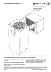
1
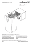
GB Refrigeration units EVO-COOL® Installation and operating Instructions 6008309-01 GB Ensure compliance with the following instructions prior to beginning work on the Refrigeration unit: Installation, cleaning maintenance and repair work must be performed only by a refrigeration specialist company. Technical modifications and manipulation are prohibited. Work on the Refrigeration unit is authorised only when the mains plug has been removed. The Refrigeration unit must be protected against unauthorized activation by appropriate means (e.s. warning sign). The directives, VDE 0105 Part 1, for working on electrical equipment must be complied with. Non-compliance will result in forfeiture of all warranty claims. General notice (liability): the details of this technical documents serve for description. Consents regarding the availability of certain features or regarding a certain purpose always require a special written agreement. Page 1 We reserve the right to make technical changes! Status as of 02.15 GB Table of contents 1. 1.1 1.2 Description Refrigeration unit Deep-freeze unit 2. 2.1 2.2 2.3 2.4 2.5 2.6 2.7 2.8 General information Excepts from our warranty conditions Standards and regulations Requirements for the installation room Transport Delivery condition Unpacking and handling Energy conservation Decommissioning 3. Cleaning and maintenance of the refrigeration unit Disposal of cooling agent 3.1 4. Installation of a EVO-COOL® in a Viessmann coldroom 9. 9.1 9.2 9.3 9.4 9.5 9.6 9.7 9.8 9.9 Menu Enabling Display Menu Settings Menu Information Menu LogBook Menu Program Menu Change Board Menu Data Exchange Menu Warnings 10. 10.1 10.2 10.3 10.4 Bus operation Connection of the units and the display Bus operation modes Bus operation faults Mains connection 11. 11.1 11.2 11.9 Fault rectification Refrigeration unit is not running Refrigeration unit is running, but the display is not working Thermal detector defective. • RF–breakage / short circuit • Liquefaction detector not working correctly • Log. detector not working correctly Fault with the package detector High pressure Cold room temperature too high Cold room temperature too low Refrigeration unit constantly runs and the evaporator is icy Door open 12. Refrigeration circulation schematic 13. Electrical circuit diagram for 230V / 1~ / 50Hz 14. Electrical circuit diagram for 400V / 3~ / 50Hz 15. Technical data 16. Explanation of Conformance CE 11.3 5. 5.1 5.2 5.3 Electrical power supply cold room Connection of the door contact switch Connection of the fault indicator contact Power supply connection and commissioning 6. 6.1 6.2 6.3 6.4 Defrosting Defrosting process Defrosting options Defrost water drain Preventing excessive defrost water 7. 7.1 7.2 8. Cooling mode How the cooling mode works Description of the cooling mode types 11.4 11.5 11.6 11.7 11.8 Operation of the regulation First steps EVO-COOL® General notice (liability): the details of this technical documents serve for description. Consents regarding the availability of certain features or regarding a certain purpose always require a special written agreement. Page 38 GB Right reserved to make technical changes! GB 1. Description 2.2 The units are designed for the prescribed temperature anges. If they are operated outside the prescribed temperature range for several days, the possibility of a serious defect on the refrigerating unit cannot be discounted. 1.1 The EVO-COOL® refrigeration unit has been built and inspected according to the standards and regulations valid at the time of manufacture. It complies with the EMC Directive 2004/108/EC, machinery directive 2006/42/EG. The unit has been inspected at the factory for refrigeration circulation leakage and for function. Refrigeration unit EVO-COOL® CS 500, CS 900, CS 1300, CS 1500, CS 2000, CS 2500, CS 3000 The units are designed for the cooling of rooms, in which goods are stored at temperatures of -5°C to +20°C. Standards and regulations 2.3 Requirements for installation area / Intended use The Refrigeration unit must not be assembled outdoors. 1.2 Deep-freezing unit EVO-COOL® FS 900, FS 1200, FS 1400, FS 2000, FS 2500, FS 3000 The units are designed for the cooling of rooms, in which goods are stored at temperatures of -25°C to -5°C. 2. General information 2.1 Excepts from our warranty conditions The warranty is valid for 1 year. The period of entitlement begins on the day of delivery, which must be verified by the Bill of delivery or Invoice. Within the period of warranty, functional defects attributed to faulty design or material defect will be rectified at no charge. Claims in excess of these, in particular those related to consequential damage, are excluded. We will accept no liability for damages, which result from improper or unauthorised utilisation, faulty installation or commissioning on the part of the customer or a thirdparty, natural wear and tear, faulty or negligent handling, chemical, electro-chemical or electrical influences, as long as the fault cannot be attributed back to actions taken on our part, non- compliance with Installation, Operating and Maintenance Instructions, improper modifications or repair work on the part of the customer or a third-party, as well as the influence of replacement parts from thirdparty origin. Warranty entitlement is forfeited, as well, if the refrigeration circuit has been opened by unauthorised personnel, access has been made to the system assembly, or the serial number has been changed or made unrecognisable. The Refrigeration unit must be setup to ensure the free intake and discharge of air. In the event the use of air ducts is unavoidable, project planning must be made by a refrigeration specialist company. Sufficient free space must be provided for in front of the Refrigeration unit intake and discharge openings in order to warrant a good air flow: - minimum 250 mm in front of all intake and exhaust openings If it is not possible to maintain this clearance, then sufficient air flow must be warranted by means of suitable measures (air deflector, air ducts, additional ventilators). The unit must not be deployed in areas where strong strong magnetic interfering impulses are anticipated or in the vicinity of transmitting antennas. The unit must not be setup in an explosive atmosphere! The unit must not be setup in a fire-endangered operating site! According to DIN VDE 0100-482 (VDE 0100 Part 482), this is: 1997-08 Rooms or locations in rooms or in the open, in which, with respect to the local and operational circumstances, the danger exists that highly inflammable materials could come so close to the electrical equipment at such hazardous levels that the higher temperatures of this electrical equipment or electric arcing create a fire hazard. This includes: Working, dry and storage rooms or sections of rooms, as well as similar outside locations, such as paper, textile and wood processing operations, hay, straw, jute or flax storage yards. - According to BGR 500, chapter 2.35 or local regulations for operation and maintenance. (qualified staff) General notice (liability): the details of this technical documents serve for description. Consents regarding the availability of certain features or regarding a certain purpose always require a special written agreement. Page 39 GB Right reserved to make technical changes! GB 2.4 Transport The Refrigeration unit must be transported in its operating position due to oil in the compressor. For possible further transport, only the original packaging may be used. 2.8 Decommissioning Temporary decommissioning The refrigeration unit is decommissioned as follows: - Turn the knob to Standby mode then press to confirm. - Select Standby Yes. 2.5 Delivery condition The refrigeration unit is delivered in a carton, operationally ready and wired for immediate plug-in. A signal sounds as a warning (approx. five seconds) while the system switches to the selected mode. Check whether Standby mode is displayed on the system: 2.6 Unpacking and handling - Prior to and during the unpacking of the Refrigeration unit, a visual inspection should be made in to de termine whether possible damage has occurred during transport. - Please pay attention to loose parts, dents, scratches visible oil loss, etc. - Before disposing of the packing material, a check of it should be made to ensure that no loose parts are hidden in it. - In order to process warranty claims, please provide an exact description of the deficiency (with picture if possible), as well as information as to unit model designation and serial number. - In order to protect the unit from damage, it must only be transported in its operating position. It must be ensured that the evaporator and condenser units have not been damaged. Non-compliance will result in forfeiture of the warranty entitlement. 2.7 - The current setting is displayed in the small window on the side. - If Yes is displayed, the system does not start up. The current statuses of the components can be viewed in the Information menu. Longer-term decommissioning The refrigeration unit is decommissioned as follows: - Turn the knob to Standby mode then press to confirm. - Select Standby Yes. - If Yes is displayed, the system does not start up. - Disconnect the refrigeration unit’s mains plug to disconnect the refrigeration unit from the mains. Energy conservation Direct sunlight will raise the consumption of electricity. Avoid any unnecessary or too lengthy opening of the door. Monitor the storage temperature. Regularly clean the Refrigeration unit. A clean unit saves energy and has a longer service life. Observe cleaning intervals (see Chapter “Cleaning and maintenance of the Refrigeration unit”). Regular maintenance increases the service life. General notice (liability): the details of this technical documents serve for description. Consents regarding the availability of certain features or regarding a certain purpose always require a special written agreement. Page 40 GB Right reserved to make technical changes! GB 3. Cleaning and maintenance of the Refrigeration unit Attention! The mains plug must be removed from the socket and protected against re-insertion for all cleaning and maintenance work. Following commissioning, the Refrigeration unit should bechecked periodically and cleaned as necessary. The time span between the checks or cleaning should be established based on the level of contamination. The time interval for cleaning is dependent on on the ambient conditions. Yet, at least one maintenance inspection should be performed annually. The evaporator unit should be cleaned, either with a soft cleaning brush, with compressed air or, in case of with heavy grease deposits, with an industrial cleaner. Do not use any sharp or sharp edged object for cleaning. It must also be ensured that the thin lamella fins are not bent or damaged during the cleaning process. Do not spray the unit with water or steam! 3.1 Disposal of cooling agent If the Refrigeration unit must be replaced with a new unit, ensure that the Refrigeration unit pipelines are not damaged to the point that the cooling agent leaks out. Defective Refrigeration units or extracted cooling agent must be disposed of in a manner compatible to the environment and in accordance with applicable regulations. General notice (liability): the details of this technical documents serve for description. Consents regarding the availability of certain features or regarding a certain purpose always require a special written agreement. Page 41 GB Right reserved to make technical changes! GB 4. Installation of a EVO-COOL® in a Viessmann coldroom Sufficient free space must be provided for the intake and discharge openings on the left side of the refrigeration unit in order to warrant a good air flow: - at least 250 mm from all ventilation openings. A wall element can be delivered by us with the respective cut-outs and bore holes for installation in the cold storage cell. Installation template Otherwise, the required bores holes and cut-outs should be made on location by a refrigeration technician using installation templates or the dimensional drawings. The cutting edges and bore holes must be protected against corrosion with zinc primer paint. Attention! The electrical power supply should first be connected at commissioning after installation has been completed - Risk of life! Loosen the holding angle from the unit. To prevent ice formation and not restrict access for servicing, should be maintained between the coldroom wall and the evaporator, a minimum distance of 50 or 100 mm. > 50 mm > 100 mm General notice (liability): the details of this technical documents serve for description. Consents regarding the availability of certain features or regarding a certain purpose always require a special written agreement. Page 42 GB Right reserved to make technical changes! GB Hang the unit on the storage cell wall while pushing against it from the outside. Slide the holding angle against the inside cell wall and tighten it securely with one or two bolts. Loosen the locking screws (2 ea.) on the front access cover. Pull the front panel at the bottom a little bit forward then push it upwards and take it off by pulling it forward again. Units without a display have two additional screws on the front cover General notice (liability): the details of this technical documents serve for description. Consents regarding the availability of certain features or regarding a certain purpose always require a special written agreement. Page 43 GB Right reserved to make technical changes! GB Slide the enclosed plastic collar (D) over the defrost water drain hose (B). Guide the defrost water drain heater (A) completely through the defrost water drain hose (B), and in this process, for easier insertion, the defrost water drain hose (B) must be pulled as much in a straight line as possible. Guide the defrost water drain hose (B) through the bore hole (G, ø 31 mm) in the cell wall (F) from the inside. Lubricant can be used if necessary. Connect the defrost water drain hose (B) to the drain port (E) on the evaporator condensate tray. Put the defrost water drain heater (A) into the siphon (C). Push the siphon (C) from the inside onto the defrost water drain. Guide the defrost water drain into the defrost water tray. Cover the cut-out (G) for the defrost water drain hose (B) with the plastic collar (D). General notice (liability): the details of this technical documents serve for description. Consents regarding the availability of certain features or regarding a certain purpose always require a special written agreement. Page 44 GB Right reserved to make technical changes! GB Push the enclosed defrost water tray with the side clips (P) in the lower guide up to the end of the evaporator line to the back. Then push the tray upwards and ca. 10 mm to the back, again. The defrost water tray is correctly positioned if the side clips (P) on the defrost water tray are positioned on the metal clips (Q). Fill out the area above the Refrigeration unit hanging rail with the enclosed Armaflex hoses (N) as sealing material. * Seal the rail with sealant if necessary. P Remount the front access cover, securing it to the unit with the enclosed sheet-metal screws. Attention! If cable ducts or the like are to be installed next to the Refrigeration unit, a space of 30mm must be maintained between the cable duct and the unit to ensure that the unit sidewall can be removed for maintenance work. * * General notice (liability): the details of this technical documents serve for description. Consents regarding the availability of certain features or regarding a certain purpose always require a special written agreement. Page 45 GB Right reserved to make technical changes! GB 5. Electrical power supply cold room A 4-pole socket outlet is located on the intake-side of the Refrigeration evaporator unit for the electrical power supply to the loads attached to the coldroom, with a total power capacity of max. 250 VA (lighting, door frame heating). The door contact switch can also be connected to this sokket outlet. 5.1 Mains connection 230V AC via multi-pin connector Connecting the door contact switch The evaporator ventilator should be switched off when the cold storage cell is opened. For this reason, we recommend the installation of an potential-free door contact switch (switching capacity 230VAC, min. 0.5 A). Connection takes place via the 4-pole socket outlet mounted on the intake-side of the evaporator unit. In its delivered condition, the unit is functionally ready for service without an external door contact switch. The door contact switch is not included within the scope of delivery of the unit. If a door contact switch is connected to the refrigeration unit, the regulation parameter must be changed (see also Point 9.3, Menu Settings). This is achieved through the following menu items: Settings Limiting values/Alarm Door contact Yes/No 5.2 Door contact switch (optional) Connection of the fault indicator contact The electronic control unit is outfitted with a potentialfree Fault report contact for connection to the on-site Fault reporting equipment (max. 10A, 230VAC). The mains side electrical power outage is not monitored. 11 In the event of a fault, contacts IN and NO are closed. The connection is located on the circuit board (plug connector X4). 14 12 X4 IN NO NC General notice (liability): the details of this technical documents serve for description. Consents regarding the availability of certain features or regarding a certain purpose always require a special written agreement. Page 46 GB Right reserved to make technical changes! GB 5.3 Power supply connection and commissioning Attention! The electrical power supply should first be connected at commissioning - Risk of life! Work on the power supply connector and protection devices must be carried out by a specialist company, in accordance with IEC 364, local regulations and the connection conditions of the respective energy supply company! Insert the mains plug into a properly grounded outlet with personal protection measures (fault current circuit breaker) according to the specification plate. Electronic regulation The equipment starts up after self testing the regulation. A warning signal sounds upon ramping up the regulation. Unless other selection is made during ramp-up, the regulation continues with the status which was set before discontinuation of the power supply. I. e. if regulation was in a cooling mode, it continues in the same mode. If it was in standby, it will remain in that mode. General notice (liability): the details of this technical documents serve for description. Consents regarding the availability of certain features or regarding a certain purpose always require a special written agreement. Page 47 GB Right reserved to make technical changes! GB 6. Defrosting 6.1 Defrosting process When the defrost function activates, the compressor and the fan are switched off and the heater for the defrost water hose is switched on. Once the defrost water hose lead time has passed, the compressor switches on and the bypass valve opens. The heater for the defrost water hose continues running during this process. The compressor remains running until the set defrost temperature is reached in the evaporator unit or the set maximum defrost period has passed. The maximum defrost period should usually be set as a longer period rather than shorter one so that defrosting occurs in full. The correct position and thermal contact of the sensor in the evaporator unit must be checked during maintenance (see figure). Relay Compressor Solenoid valve Bypass Defrost water hose heater Time Lead time Defrosting (min) duration (min) Defrosting temp. (°C) Dripping time (min) The sensor is inserted diagonally downwards from the left between the 9th and 10th fins and the 1st and 2nd sensor tube at a depth of 34 mm. If the sensor is positioned against a tube that is close to the inflow during the defrosting process, defrosting does not complete fully. The sensor reaches the set defrost temperature prematurely and the control unit terminates the defrosting process. The ice is simply melted and sinks to the bottom. This results in a block of ice on the lower edge of the evaporator, which can only be manually defrosted by a service engineer. If the maximum defrosting period has passed or the defrost temperature has been reached, the compressor switches off and the bypass valve closes. The defrost water hose heater continues running until the dripping time has passed. The defrosting process is now complete. Insert sensor between the 9th and 10th fin Caution! When using hot gas defrosting, the process should best be conducted quickly and often. Large ice formations cannot be melted as the defrosting process works with far lower temperatures and therefore less radiant heat. Insert the sensor to a depth of 34 mm 34 mm Insert sensor between the 1st and 2nd evaporator tube General notice (liability): the details of this technical documents serve for description. Consents regarding the availability of certain features or regarding a certain purpose always require a special written agreement. Page 48 GB Right reserved to make technical changes! GB 6.2 Defrosting options Defrosting cycle The defrosting process is continually triggered at set intervals. Defrosting plan Defrosting is performed for well-defined periods. These can include 99 periods will be specified in a week time. Manual defrosting The cooling process is interrupted and a complete defrosting process is conducted. The unit then re-activates the cooling mode. 6.3 - The air flow should not be directed at the doors and pressure compensation valves. Pressure compensation valves must always be installed in a position where they are barely influenced by the air flow. - The goods introduced must be stored in sealed containers. Goods with high water content are subjected to dehydration and thus damage. (Freezer burn on deepfrozen goods and shrivelling/drying out of fresh foods) - Do not leave deep-frozen goods in the warm storage area on delivery. Defrost water will form on the surface and have to be cooled again. In the case of cardboard packaging, a great deal of moisture is absorbed in the surfaces and causes the evaporator to freeze over when the packaging is moved into the coldroom. Defrost water drain The defrost water created is caught in the defrost water tray and largely evaporated by the evaporator loops. In the event of large volumes of defrost water or high humidity around the cell installation site, the use of the evaporator may not be sufficient. In such cases, an additional defrost water drain hose can also be attached to the evaporator tray. The accessories kit is optionally available and is compatible with all FS and CS series units. 6.4 Preventing excessive defrost water Defrost water is the melted ice formed by the evaporator. In other words, the ice was formed through a use of energy and likewise melted again. Due to the thermodynamically induced lack of humidity at the coldest point in the coldroom, ice formation cannot be prevented (vapour pressure drop) but can be minimised. The following points should be noted: - Units in deep-freezing rooms should always be coupled with a door contact switch that switches off the evaporator while the door is open. - Doors should remain open for as little time as possible. If this is not possible, suitable measures must be taken to minimise the loss of cold. This can include several technical measures such as strip curtains, fast-sliding doors, air curtain systems, pre-cooling rooms etc. General notice (liability): the details of this technical documents serve for description. Consents regarding the availability of certain features or regarding a certain purpose always require a special written agreement. Page 49 GB Right reserved to make technical changes! GB 7. Cooling mode 7.1 How the cooling mode works After switching on the unit (Standby => No; see Point 8 ‘First steps’), the cooling mode activates. If the unit was only recently connected to the mains, the compressor standstill time (usually three minutes) passes. The compressor then switches on and starts the cooling process. The condenser fan switches on at an appropriate speed depending on the temperature at the condenser outlet. On reaching the ‘Start evaporator fan’ temperature or upon expiry of the ‘evaporator fan delay’, the evaporator fan switches on. Depending on the humidity setting, the fan runs at all times or when the compressor is switched on (see parameter list in Point 9.3). The compressor runs until the switch-off point is reached and re-activates when the temperature increases to the switch-on point. The points are determined by the desired coldroom temperature and the hysteresis (see parameter list in Point 9.3). Relay Compressor Solenoid valve Bypass Solenoid valve Fluid line Temperature monitoring by ambient air sensor Minimum standstill time Compressor must have finished Temperature 7.2 Time Cooling running Switch-off by ambient air sensor Lead time Bypass valve (sec) Cooling range Description of the cooling mode types Normal mode The unit is started with ‘Standby = No’ then runs continuously. The cooling mode is only briefly interrupted by the set defrost cycles. Hysteresis (2 to 8 K) Target temperature Compressor on Cooling schedule The unit is started with ‘Standby = No’ then only runs at the times approved in the cooling schedule. The cooling mode is only briefly interrupted by the set defrost cycles. The cooling schedule must always be programmed for a week. Emergency mode The emergency switch on the unit’s motherboard (see circuit diagram) has been activated. The unit runs without interruption and temperature regulation. The compressor and both fans run at maximum power. The information ‘Emergency mode’ appears on the display. Temperature Compressor off Time Compressor on Deep-freeze range Target temperature Hysteresis (-2 to 8 K) Compressor on Compressor off Time Compressor on General notice (liability): the details of this technical documents serve for description. Consents regarding the availability of certain features or regarding a certain purpose always require a special written agreement. Page 50 GB Right reserved to make technical changes! GB 8. First steps EVO-COOL® 1. Check the intactness of the refrigeration unit. If the EVO-COOL® is in order, it can be connected to the network according to the specification plate. The control unit comprises the functional units of a display, a rotary knob, a push button, the USB interface (concealed behind the cover over the display) and the mains connection. The USB interface can be used to store the data or load programme updates into the control unit (see Point 9.8). 2. The display starts to light up for 30 seconds “Please wait / Bitte warten” appears in the display. 3. The equipment starts up in the status in which it was operated before separation from the power supply. In the display, Equipment starts up appears and offers Start and Standby for selection. If the equipment does not start up, turn the rotary knob to Standby (with light background) and then press the selector switch. While the equipment switches to this mode, a signal tone is heard (ca. 5 seconds) as warning. 4. The rotary knob has the following function: - Turning = Selection - Pushing = Selection of the function If the button is pushed for a longer period of time, the menu selection goes back to the top level. 5. With the rotary knob, select Enabling and input the numerical sequence 12345. After correct input, Welcome appears in the display. By pushing the rotary knob further, the control goes to the main menu, again. If the numerical sequence is not correct (Login Error), please contact your refrigeration specialists. The relevant person with the higher user privileges can modify the access parameters for the level below. 6. The next step is temperature setting. For that, the Program menu must be selected. This includes the submenu items Temperature , Standby , Time Schedule , back . Select the Item Temperature and set this to the corresponding value. Acceptance is performed by pushing the rotary knob. 7. Check if the equipment is in a Standby mode. It is sufficient to scroll to the item and the little window on the side displays the instantaneously adjusted value. If the display shows Yes, the equipment will not start up. If the equipment should cool down, select Standby , then No and confirm this by pushing the rotary knob. If the compressor has been running previously, the standing time compressor SZV starts. 3 minutes are set as a default value. 8. Under the menu item Information , you can query the current status of the components. Apart from short specification on the side, the lower edge of the display shows the long specification in addition. In the case of equipment parts with a switch-on function, 0 appears for Off and / for On. General notice (liability): the details of this technical documents serve for description. Consents regarding the availability of certain features or regarding a certain purpose always require a special written agreement. Page 51 GB Right reserved to make technical changes! GB 9. Operation of the regulation Menu Enabling 9.1 A 5-digit code can be used for log in. The unit must be released for all operation, including Standby mode or temperature changes. This provides protection against accidental changes. In the original state, the passwords for the user 12345 the service 90210 If the access rights are to be modified or for specific users they are inaccessible, the passwords need to be modified. When losing the passwords, their modification may only be performed by Viessman Kühlsysteme GmbH! 9.2 Display Sub-menu and parameters Selection window main menu Main menu Parameter value Bus number of the currently active aggregate (1-8) Room temperature Settings Warnings Change Board Enabling Information LogBook Data Exchange Program General notice (liability): the details of this technical documents serve for description. Consents regarding the availability of certain features or regarding a certain purpose always require a special written agreement. Page 52 GB Right reserved to make technical changes! GB 9.3 Menu Settings Submenu 1 Language Submenu 2 Values Presetting CS Cooler FS Freezer German After changing the language setting, the unit must be restarted. Up to 8 different languages can be stored. The English standard languages are German, English and French. In order to activate the changeover to another language, the language must be selected and then, the equipment disconnected from the power supply for a short time. Upon restarting, the new language is activated. French Turkish Russian Polish Name refrigeration unit Board1 Board1 Operating parameters Humidity Hysteresis Description High/Low -8K to -1K and 1K to 8K High +2K A name can be assigned for each refrigeration unit. In the case of bus operation, inputting the name for the assignment of rooms is helpful. In addition to the name, the unit number has to be input at the DIP switch, as well. Since up to 8 different refrigeration units can be controlled with one display, a logical structure of the name specifications is definitely required. (See Electrical circuit diagram, Page 66 to 69) Low The evaporator fan runs together with the compressor. => Low relative humidity. The evaporator fan runs constantly. => High relative humidity. -2K Differntial can be changed between switch-on and switchoff temperature. If the value is negative, the refrigeration unit switches off if the cold room temperature has reached the rated temperature value minus the absolute value of the differntial. It turns on if the cold room temperature has reached the rated temperature again. Example: Rated temperature - 20°C Differntial -2K Refrigeration unit Off at -22°C Refrigeration unit On at -20°C If the value is positive, the unit turns off if the cold room temperature has reached the rated temperature value. It turns on if the cold room temperature has reached the rated temperature + differntial. Example: Rated temperature +5°C Differntial +2K Refrigeration unit Off at +5°C Refrigeration unit On at +7°C If the units are used in bus mode, a separate unit number must be set for each unit (see circuit diagram on pages 66-69)! Bus type Redundancy/ multi-cell Redundancy Redundancy Redundancy = all units run with the same setting and temperature. Defrosting and cooling occur simultaneously on all units. Redundancy in this context means that if one unit fails, the second or remaining units continue to function. The units do not monitor each other. Multi-cell = all units are controlled via a display. To facilitate allocation, each room and the applicable unit should be given its own name. To switch to a different bus mode, the unit must be disconnected from the mains. On restarting the unit, the new bus mode is activated. General notice (liability): the details of this technical documents serve for description. Consents regarding the availability of certain features or regarding a certain purpose always require a special written agreement. Page 53 GB Right reserved to make technical changes! GB Submenu 1 Submenu 2 Values Wall-hanging unit Type Ceilingmounted unit Defrosting Presetting CS Cooler Wallhanging unit FS Freezer Description Wall-hanging unit: in the case of redundancy, all units in the bus system simultaneously begin defrosting. Wall-hanging unit Ceiling unit: units begin defrosting separately. Restart required on selection. Time interval for the data logger. In the case of 15 min recording interval, the ring buffer lasts for min. 2 years. The data can be read out to an USB stick as well as viewed and processed in Microsoft® Excel or OpenOffice™. In the graphic representation in the display, the time course is shown on a daily basis and can be selected in a targeted fashion within a specific day. Logging Intervall (optional) 1 min to 30 min 15 min Man. defrosting Yes / No No No Defrosting Defrost cycle / Defrost plan Defrost cycle Selection parameters for the defrost function Defrost cycle: At a predetermined interval of the defrosting operation is started. Defrost plan: By setting the shift points for the defrost deDefrost cycle frosting can be performed for well-defined periods. Defrosting must be programmed for a week. For 99 switching points are available. When changing the defrost to restart the system is required. Defrosting duration 1 min to 60 min 10 min 10 min Time limitation for defrosting in a cycle. 2,5 h Defrosting cycle: the defrosting process starts at a specified interval. Example: Every 2h defrosting cycle for a duration of 30 minutes => at 2:00 pm, defrosting is performed for 30 minutes, at 4:00 pm, defrosting is performed for 30 minutes, at 6:00 pm, defrosting is performed for 30 minutes. For limitation on defrosting, the defrosting limitation temperature is also applied. Thus, defrosting is performed for a maximum period of 30 minutes or until the defrosting limitation temperature is reached. It is better to defrost the units quickly and often than to have a long cycle period and a long defrosting process. +12°C The defrosting limitation temperature is measured in the evaporator. For switching off, the defrosting duration (time in min) or the temperature is used. Whichever value is reached sooner. If no defrost termination probe is available, only the time is considered and the process is finished after running the defrosting sequence. +5°C Switchover between hot gas and fan-only defrosting. The temperature specifies up to which temperature the defrosting is only performed with the evaporator fan. Under this temperature, defrosting is performed by the use of hot gas or electric heating, respectively. Above this temperature, the ice layer on the evaporator is melted away for cooling of the room. For that purpose, the evaporator probe must not be fully frosted. Defrosting using the fan should ideally only occur for chiller rooms. Defrosting cycle 15 min to 24 h Defrosting 0 to +40°C temperature Switching point +3°C to +40°C 4h +12°C +5°C 15 min Time limitation for defrosting in a cycle. General notice (liability): the details of this technical documents serve for description. Consents regarding the availability of certain features or regarding a certain purpose always require a special written agreement. Page 54 GB Right reserved to make technical changes! GB Submenu 1 Submenu 2 Drain down time Drain line heater activation pre defrost Values 0 min to 10 min 0 minto 10 min Presetting CS Cooler 3 min 3 min FS Freezer 3 min After the defrosting process, a waiting time is applied until the normal operating mode (cooling) is returned. In the case of hot gas defrosting, the compressor downtime runs concurrently. I. e. the cooling operation can only start after elapsing of this time. 3 min Lead time for the drain line. Starts prior to the start of the defrosting process. Thus, the defrosting water does not drip on the cold dripping tray and in the cold drain hose. Yes Displays the temperature before defrosting began in the data logger during defrosting and prevents temperature peaks during defrosting. Drain pre heat Freezing temperature Yes / No Yes Description Back Rotary speed Fan max. 100% Standard Eco-Linear – Activation of the fan with 230 V and the control output 0-10 V linear. – Activation with a straight line through the defined points temperature 5 / speed 5 (lower point) and temperature 1 / speed 1 (upper point). Pr. Evap. 0 min to 10 min 3 3 Delays the start-up of the evaporator fan together with the start temperature of the evaporator fan. Sub. Evap. 0 min to 10 min 0 0 Uses the residual cold from the evaporator. Fan type 1 5 5 1 Temperature Start Evap. -20°C to 10°C +5°C -15°C Delays the start of the evaporator fan after defrosting or a restart together with the delay time. Temp Step 1 Min. value v. temp. intervals of 5 to max. 50°C +35°C +35°C Upper temperature point for speed regulation. (See figure) Temp Step 5 min. 0°C to max. value v. temp 5 0 0 Lower temperature point for speed regulation. (See figure) min. value v Rotary speed 1 rotary speed 5 to 80 max 100% 80 Upper percentage for speed regulation. (See figure) min. 0% to max. Rotary speed 5 value v. rotary speed 5 0 Lower percentage for speed regulation. (See figure) 0 Back General notice (liability): the details of this technical documents serve for description. Consents regarding the availability of certain features or regarding a certain purpose always require a special written agreement. Page 55 GB Right reserved to make technical changes! GB Submenu 1 Limiting values/ alarm Submenu 2 Values Presetting CS Cooler FS Freezer Description Mute time off 0 min to 99 min 60 min 60 min Duration for which a confirmed error is suppressed. Alarm delay time for temperatur 0 min to 99 min 60 min 60 min Time interval after which the upper or lower temperature alarm has been triggered. Pr. Time door 0 min to 10 min 4 min 2 min Duration after which the door alarm should be triggered (only in the case of installed door contact switch). Door contact (optional) Yes / No Yes / No Yes / No Determination of whether the inlet door contact switch can be evaluated. Personal alarm (optional) Yes / No Yes / No Yes / No Determination of whether the inlet personnel alarm can be evaluated. Filter alarm (optional) Yes / No Yes / No Yes / No Determination of whether the inlet filter alarm can be evaluated. High temp. alarm 0 K to 20 K 10 K 10 K The value set added to the cut in temperature is the high alarm set point. Low temp. alarm 0 K to 20 K 5K 5K The value set added to the cut out temperature is the low alarm set point Back Network Attention! The settings under this menu item require a restart! Use DHCP Yes / No Automatic address assignment via server (DHCP) IP-address (enter the number) Manual input of the IP address. Subnet mask (enter the number) Manual input of the subnet mask. Gateway (enter the number) Manual input of the Gateway. User Pin 12345 (User) 90210 (Service) Default entry for operator can be modified by the service personnel. T. authenticated 1 min to 60 min 1 1 Time interval after which the user at the operating panel is logged out. Contrast 10 to 50 20 20 Contrast of the screen T screen sv. 5 sec to 1000 sec 60 60 Time interval after which the screen saver is turned on. Time lighting 5 sec to 1000 sec 90 90 Time interval after which the background lighting turns off Time zones Selection table Back Control panel Time zones for switching between summer/winter time. Restart required on selection. General notice (liability): the details of this technical documents serve for description. Consents regarding the availability of certain features or regarding a certain purpose always require a special written agreement. Page 56 GB Right reserved to make technical changes! GB Submenu 1 Submenu 2 Values Presetting CS Cooler FS Freezer Description Time Time Time setting. Date Date Date setting. Data logger licence Operating field number in upper line, licence number in lower line The system number is displayed in the upper line. If the data logger is activated, the licence number also appears in the second line. If the data logger is retrospectively activated, the system number has to be sent to the factory to generate the licence number. This is then entered in the lower line. Service number Service number of the refrigeration specialist The service telephone number of the refrigeration specialist can be entered here. This is shown on the display alongside the error in the event of a fault. Service number Service number of the refrigeration specialist The service telephone number of the refrigeration specialist can be entered here. This is shown on the display alongside the error in the event of a fault. Back Activation of the pump down or pump out function. Pumpdown Deactivate Yes / No Yes Yes Restart is required on selection. NotStopp PmpDwn 10 sec to 180 Sec 10 10 Maximum pump down running time. Pumpdown time 10 sec to 60 sec 10 10 Running time of the pumpout if no low pressure switch is built in. Pumpdown delay 5 min to 60 min 15 15 Standing time for pumpout before the compressor exhausts the cooling medium again.. Low pressure sw. Yes / No No No Specification whether a low pressure switch is fitted. Back Factory settings Yes / No Resets the adjusted parameters to the preset factory parameters. General notice (liability): the details of this technical documents serve for description. Consents regarding the availability of certain features or regarding a certain purpose always require a special written agreement. Page 57 GB Right reserved to make technical changes! GB 9.4 Menu Information This menu item can be viewed without approval. All statuses that can be registered by the control unit are displayed. The brief description on the right is repeated again on the lower edge using clearer names. Submenu 1 Submenü 2 Description Board selection Board 1 Selection of the board for the information in the bottom right window as a permanent feature Room temperature °C Room temperature (side, bottom right) VDF (evaporator temperature) °C Evaporator temperature VFT (condenser temperature) °C Condenser temperature LT (data logger temperature) °C Data logger DV (Condenser fan speed) % Condenser speed VDA (evaporator fan) 0/1 (off/on) Evaporator VDI (compressor) 0/1 (off/on) Compressor VFL (condenser fan) 0/1 (off/on) Condenser SU (summer active) 0/1 (off/on) Summer ST (Fault) 0/1 (off/on) Fault FS (compressor frost protection) 0/1 (off/on) Frost protection SZV (waiting time compressor countdown) 0/1 (off/on) Compressor waiting time MV (solenoid valve) 0/1 (off/on) Solenoid valve BV (bypass valve) 0/1 (off/on) Bypass valve Rf (room sensor) ok/not ok Room sensor RT ^ (room temperature too high) ok/not ok Room temperature too high RT v (room temperature too low) ok/not ok Room temperature too low VDF (evaporator unit sensor) ok/not ok Unit sensor VFF (condenser sensor) ok/not ok Condenser sensor HDR (high pressure fault) ok/not ok High pressure NDR (low pressure fault) ok/not ok Low pressure Door (door contact switch) ok/not ok Door alarm Per (personnel alarm) ok/not ok Personnel alarm Fil (filter alarm) ok/not ok Not (Emergency mode on) ok/not ok Filter alarm Once emergency mode is activated, the info display can no longer be selected SUZ (countdown for summer acknowledgement) sec Acknowledgement time ZBA h Time until defrosting TAU 0/1 (off/on) Defrost water hose VER (interface program version) Controller version GUI (controller program version) AGG GUI version FS = freezer CS = cooler VDIE (compressor start-ups) Unit type Compressor start-up VDILZ (compressor runtime) d/h/m VDIST (compressor waiting time) d/h/m VDAE (evaporator start-ups) Compressor runtime - day/hours/minutes Compressor waiting time - day/hours/minutes Evaporator start-up VDALZ (evaporator runtime) d/h/m Evaporator runtime - day/hours/minutes VDAST (evaporator waiting time) d/h/m Evaporator waiting time - day/hours/minutes VFLE (condenser start-ups) Condenser start-up VFLIZ (condenser runtime) d/h/m Condenser runtime - day/hours/minutes VFLST (Condenser waiting time) d/h/m Condenser waiting time - day/hours/minutes General notice (liability): the details of this technical documents serve for description. Consents regarding the availability of certain features or regarding a certain purpose always require a special written agreement. Page 58 GB Right reserved to make technical changes! GB 9.5 Menu LogBook 9.5.1 Mode of operation All recordable faults are documented in the log book and stored in a continuously updated ring memory. Depending on the volume, the faults are stored for at least three months and then overwritten. The data can be exported and evaluated (*txt format). The data in the memory cannot be deleted. For a better overview, the day on which a fault occurred is underlined in the date selection. Once this day has been selected, the temperature display or the event display can be accessed. The temperature data (optional) is also recorded. The ring memory can last for two years with a 15-minute recording interval. After two years, the oldest data records in the ring memory are overwritten. The logged data can be directly output onto the display or read via a data carrier. The data (* .txt format) can be imported into a spreadsheet and evaluated. The data in the memory cannot be deleted. 9.5.2 Licence release If the data logger is retrospectively ordered, the display number must be reported to the factory. The display number can be found under Settings, Control panel, Licence. This display number is allocated to a release number in the factory, which is entered under the display number. Once the release number has been entered in the display, the temperature data is recorded. Submenu 1 Year/month/day (if a day is underlined, an event has been logged) Submenu 2 Description Temp. graph/result The display can be selected through rotation and pressing. The results can be viewed for some time into the past. The length of time depends on the number of faults. Depending on the frequency, the oldest faults are deleted (ring memory). Temperature axis Temperature graph +12°C Loggertemperature Bus number of the currently active aggregate (1-8) 14 Apr 2012 Date field 12:45 Time axis Time of the measuring point Room temperature The possible malfunctions / alarms are shown in the timeline in the form of small dots. General notice (liability): the details of this technical documents serve for description. Consents regarding the availability of certain features or regarding a certain purpose always require a special written agreement. Page 59 GB Right reserved to make technical changes! GB 9.6 Menu Program Submenu 1 Submenu 2 Values CS Cooler FS Freezer +5°C -20°C Description Cooling range -5°C to +20°C Setting value +5°C Temperature Target temperature input. Freezing range -5°C to -25°C Setting value -20°C Standby Yes / No Switching from standby to cooling. 99 switching units possible. If dates are set in the cooling schedule, the unit only runs in the set time frame. For continual operation, the cooling schedule must be deleted. New Cooling schedule Start: day (e.g. Monday) Time: time (e.g. 12:00) End: day (e.g. Tuesday) Time: time (e.g. 12:00) Save Delete Back Back General notice (liability): the details of this technical documents serve for description. Consents regarding the availability of certain features or regarding a certain purpose always require a special written agreement. Page 60 GB Right reserved to make technical changes! GB 9.7 Menu Change Board Access to the respective unit in bus mode 9.8 Menu Data Exchange Data access via USB connection Update Software A software update is possible The current software status is shown on the homepage of the Viessmann Kühlsysteme GmbH (www.viessmann.de/kuehlsysteme). For the download, the e-mail address and the company must be specified. Copy event file The malfunctions in the last few months can be downloaded to a USB stick. The file can be opened with OpenOffice™ or Microsoft® Office. USB port Knob - Rotate = Selection - Short press = Select the function Copy temperature file The data from the data logger (optional) can be downloaded to an USB stick. The file can be opened with OpenOffice™ or Microsoft® Office. Remove USB stick To prevent data losses or damage to a USB stick, select the menu item Remove USB stick before disconnecting the stick from the control unit. 9.9 Menu Warnings Current warnings are displayed up to confirmation. General notice (liability): the details of this technical documents serve for description. Consents regarding the availability of certain features or regarding a certain purpose always require a special written agreement. Page 61 GB Right reserved to make technical changes! GB 10. Bus mode 10.1 Connection of the units and the display The units are connected together using a CAT5E data cable and an RJ45 plug connector. The display must always be connected using the upper socket (see circuit diagram). A bus address must also always be allocated to each unit (binary code address on the controller board via DIP switch, see circuit diagram). If the units should be supplied with power via several electrical circuits, external potential equalization is required (min. 6 mm²). The potential difference must not exceed 2 V. If this does not occur, the data connection can be destroyed and the cooling mode disrupted. 10.2 Display and bus DIP switch Address 1 2 3 1 0 0 0 2 1 0 0 3 0 1 0 4 1 1 0 5 0 0 1 6 1 0 1 Bus operation faults 7 0 1 1 In the event of outages within the network, the units always continue running with the last parameters to be transmitted from the display. When the connection is restored, the system automatically adjusts. 8 1 1 1 - Bus type: redundant The units run jointly in a coldroom with the same parameters. For FS and CS units, the model ‘wall-hanging unit’ must be selected (see parameter list). The model controls the defrost function so that all units are simultaneously defrosted. If the option ‘ceiling unit’ is selected, the units defrost at different times. For wall-hanging units, this would lead to ice formation. 10.4 Switch for bus address Bus operation modes - Bus type: multi-cell Up to eight coldrooms with different temperatures can be managed on a display. To better allocate the units to the rooms, the units can be given a name (see parameter list). 10.3 Emergency switchoff lower "Off" Mains connection The mains connection is located on the circuit board in the housing. To connect the unit, the housing must be opened and connected using a suitable data cable. The control unit can be connected via a mains cable. The connection occurs via a web browser and the appropriate IP address. Access is gained by entering the username ‘admin’ plus the applicable authorisation number (1234 for users and 90210 for service personnel). Internet access must be accordingly released. This occurs via the IT support team at the installation site. General notice (liability): the details of this technical documents serve for description. Consents regarding the availability of certain features or regarding a certain purpose always require a special written agreement. Page 62 GB Right reserved to make technical changes! GB 11. Fault rectification Attention: Before working on electrical components and on the unit the equipment must always be disconnected from mains! Risk through electrical power and rotating (fan) and hot parts (pipes, condenser, heat exchanger)! Problem Description / Reason Correction Refrigeration unit is not running. Power plug is not connected. Connect the power plug and check the mains fuse. If you cannot determine a defect, contact an expert company. The supply voltage and frequency must always match the values specified on the type plate. Mains voltage not applied Check whether the voltage specified on the type plate is applied. Check whether the fuse protection is also ensured according to the ratings on the type plate. Ensure voltage supply. Evaporator fan starts up briefly, but the display is not working. Check wire connections of bus lines. The display connection must always remain plugged in to the upper socket! In the bus operation, the connection between the power boards is not specified. Mains voltage not applied Check whether the voltage specified on the type plate is applied. Check whether the fuse protection is also ensured according to the ratings on the type plate. Ensure voltage supply. The fuse on the PCB (base board) always trips. Check wiring of door contact switch. The n-conductor always switches! Short circuit occurs when mixed up! Unplug door contact connection (X2) and try again. If the fault is still present, unplug devices (connectors X3A to X3H) and try again. Work on electrical systems must only be conducted by qualified electricians. Refrigeration unit is running, but the display is not working. Briefly press the rotary knob. If still no display, check wire connections of the bus lines. The display connection must always be plugged into the upper socket of the power board! (see Electrical circuit diagram, Page 66 to 69) After the “Time Lighting” process (main menu “Settings”, sub-menu “Control Panel”), the display will go to sleep. Refrigeration unit is running, but the display is not working. Thermal detector defective. One or more detec• RF–breakage / short tors are defective. circuit • Liquefaction detector not working correctly • Log. detector not working correctly Up to 4 thermal detectors PT1000are built into the EVO-COOL®. The display will show which detector is defective (e.g. Log. detector not working correctly). To change a detector, please contact your refrigeration specialist. If the machine is not longer running, you may turn on the emergency operation with the DIL switch on the main board. The machine will then continue running without temperature regulation and defrosting. The refrigeration specialist company must be contacted immediately for maintenance! If the condenser, evaporator and/or condenser fan are not running and the solenoid valve for the fluid line has been actuated, a damage on the PCB is present which prevents the selection. The emergency run is then also no longer ensured. Fault with the package detector. The package detector is defect. If the message ‘Package detector fault’ appears, a check must be conducted to see if the evaporator is covered in ice. Before replacing the detector, first remove the ice and check the detector’s position. The detector must not touch the evaporator’s tubes. If the detector touches the tubes, the defrost period is too short and the ice does not melt as the defrost temperature is reached prematurely. High pressure. Fault within the refrigeration cycle regarding high pressure. The safety pressure switch (pressostat) has been activated. If the fault does not disappear following acknowledgement, please contact your refrigeration specialist. The safety circuit can contain not only the high pressure switch but also other components. (See the circuit diagram on pages 66 to 69). Unit runs continuously and the evaporator ices over. General notice (liability): the details of this technical documents serve for description. Consents regarding the availability of certain features or regarding a certain purpose always require a special written agreement. Page 63 GB Right reserved to make technical changes! GB Problem Description / Reason Correction Cold room temperature too The upper alarm high. limit for temperature monitoring was exceeded by the delay time of the temperature alarm. If the temperature continues to be above the alarm limit after acknowledgment of the fault, the delay time will start over. Check whether the doors are closed and the machine is cooling. You may read the current detector values under the menu item “Information”. If the package detector reads below room temperature, the machine is cooling. Check whether too many warm items were brought in for storage. Is the evaporator icy? Initiate manual defrosting and afterwards check if the evaporator is free of ice. Is the alarm limit to close to the hysteresis? Is the delay time set too short? Check, if the cold-water circulation (with devices with plate heat exchanger) is working correctly. Check if the air heat exchanger is supplied with enough cold air (air exchange). Cold room temperature too low. Check the temperatures in the cool room. Was the temperature adjusted lately? Were large amounts of goods brought in that had a significantly lower temperature? The lower alarm limit was under-run by more than the set alarm delay time. Refrigeration unit constant- Due to inflow of ly runs and the evaporator warm moist air, is icy. a crust of ice is building up on the evaporator. Are the siphons filled with water? Initiate manual defrosting and watch whether the evaporator is free of ice after the process is complete. If it is not, - The defrosting cycle is too long and the defrosting time is set too short. - The defrosting limitation temperature is set too low and prematurely turns off the defrosting process. - Check whether the door closes correctly and is air-tight. Adjust if necessary. - Check whether the pressure compensation valve is ok. - Check whether the pressure compensation flap closes properly - Check whether the filter fleece is correctly positioned - Check whether the package detector is correctly positioned (not touching the evaporator tubes) - Check whether moisture has infiltrated through the delivery of goods or personnel movements - Check whether the cell environment is extremely damp (vapour pressure) Door open. The door was opened for longer than released by the monitoring time. If this is not the case: Is the door contact switch installed and activated by the door? The signal input for the door contact switch is open. If the door contact switch is not installed, the position “Door Contact Switch” in the “Settings” menu / “Alarm Limit Values” must be set to “No”. In this menu you may also set the alarm time for the door. Prevent leaving the doors open for long periods as this leads to ice formation on the evaporator and the cell. Emergency operation. The display reads “emergency operation”. The emergency operation was turned on via the DIL switch on the main board. The machine will continue running without temperature control and defrosting. The refrigeration specialist must be contacted immediately or was contacted to perform maintenance. If the condenser, evaporator and/or condenser fan are not running and the solenoid valve for the fluid line has been actuated, a damage on the PCB is present which prevents the selection. The emergency run is then also no longer ensured. General notice (liability): the details of this technical documents serve for description. Consents regarding the availability of certain features or regarding a certain purpose always require a special written agreement. Page 64 GB Right reserved to make technical changes! GB 12. Refrigeration circulation schematic 4 7 13 16 P> 15 14 12 2 6 1 14 3 8 9 1 2 3 4 5 6 7 8 9 10 11 12 13 14 15 16 Compressor Pressure line Hot gas line / dripping tray Air cooled condenser High pressure switch (low pressure switch) Inside heat exchanger Collector - drier Thermal expansion valve Evaporator Suction line Coldroom Magnetic valve, fluid line Magnetic valve, hot gas defrosting Schrader-test connectors Solenoid valve pressure line Non-return valve General notice (liability): the details of this technical documents serve for description. Consents regarding the availability of certain features or regarding a certain purpose always require a special written agreement. Page 65 GB Right reserved to make technical changes! 13. Electrical circuit diagram for 230V / 1~ / 50Hz Power board (Part number 00173920) 11 F 6,3A tr 14 PE L N N L X3E PE L N N L X3D X3C PE X3G X3F PE L N PE X3B L PE N PE L PE X2 X3H L N X3A PE L N X1 12 X4 N L PE 1 IN NO NC N Alarm contact potential free GEYE BK BU BN Electric supply M 230 V AC 50 Hz ~ 16 A K-characteristic personal protection measure FI protection switch Compressor 230V 1~ Magnetic valve Hot gas bypass Magnetic valve Fluid line Oil sump heating (optional) M ~ M ~ Condenser fan A 230V 1~ Condenser fan B 230V 1~ (optional) M ~ Heating in the defrost water hose (Heating in the drip tray) PE L N GB 1 2 3 1 4-pole multi-contact plug Evaporator fan 230V 1~ PE L N 13 Door contact switch 14 Door element (extract / optional) Attention! Please optional note on page 67 and 69 emergency operation. Switch for bus address Emergency switchoff lower "Off" Display and bus Contacts JST plug Attention! Before pulling a plug, the equipment must be brought to a zero potential status! B1 I Bus 0 A1 A2 General notice (liability): the details of this technical documents serve for description. Consents regarding the availability of certain features or regarding a certain purpose always require a special written agreement. Page 66 GB Right reserved to make technical changes! IN 12V+ 12V+ 16 A1 A2 IN IN 12V+ ϑ 13 12 12 12V+ 18 A1 A2 IN ϑ 21 A1 A2 IN 12V+ ϑ 12V+ IN IN IN 12V+ ϑ Data logger detector PT 1000 Condenser sensor PT 1000 Evaporator sensor PT 1000 Room air sensor PT 1000 Filter passage switch liquefier (optional) Low pressure switch High pressure switch A2 13 21 Optional for emergency switch Personal protection circuit (optional) IN X5 /12 A 9 Volt ND B A1 A2 14 IN X5 /11 A2 +12V X5 / 11 A1 22 A1 A2 A Out+ 11 17 A1 A2 max 8 m max. 15 m 12V+ A1 A2 Display (Part number 00173921) 12 12 HD Power lengths: Power board / display Power board / Power board 12V+ IN 15 14 A1 Emergency circuit externally (optional) IN A2 Upper display and bus lower bus (optional) RS 485 via RJ 45 cable 13 A1 A2 GND 12 A1 Fan speed liquefier X5 11 Upper display and bus lower bus (optional) RS 485 via RJ 45 cable GB Wiring in the case of HD/ND switch (optional) C 1 2 3 4 5 6 7 8 DIP switch 1 2 0 0 1 0 0 1 1 1 0 0 1 0 0 1 1 1 Ethernet interface RJ 45 3 0 0 0 0 1 1 1 1 GEYE BU BN BK conductor coloring green/yellow grün/gelb blue blau brown braun black schwarz Version 2012/11/30 00250227_01 Steuerung 1 phasig.cdr Adresse USB port for data exchange General notice (liability): the details of this technical documents serve for description. Consents regarding the availability of certain features or regarding a certain purpose always require a special written agreement. Page 67 GB Right reserved to make technical changes! 14. Electrical circuit diagram for 400V /3~ /50Hz Power board (Part number 00173920) 11 F 6,3A tr 14 N N PE L L PE L X3H X3G X3F X3E PE N N L L N PE X3D X3C PE PE L N X3B L PE PE L N X3A L L PE 1 IN NO NC N Alarm contact potential free BU BN GEYE BK Compressor control line 230V 1~ Magnetic valve Fluid line Oil sump heating (optional) Condenser fan A 230V 1~ PE Heating in Evaporator fan the defrost 230V 1~ water hose (Heating in the drip tray) Condenser fan B 230V 1~ (optional) PE L N Magnetic valve Hot gas bypass M ~ M ~ M ~ 1 2 3 1 L 4-pole multi-contact plug N 13 Door contact switch 14 Door element (extract/optional) Switch box for power circuit 6 5 F2 Circuit breaker 10A B N L1 L2 L3 L1 L2 K1 Direction relay (only at Scroll) 4 PE A1 T1 T2 T3 A2 1 T1 2 T2 3 T3 M 3~ L3 PE N L1 L2 Attention! Please optional note on page 67 and 69 emergency operation. L3 Electric supply 400V 3~ 50Hz 16 A K-characteristic personal protection measure FI protection switch Attention! Before pulling a plug, the equipment must be brought to a zero potential status! Switch for bus address Emergency switchoff lower "Off" Display and bus Contacts JST plug B1 I Bus 0 A1 A2 General notice (liability): the details of this technical documents serve for description. Consents regarding the availability of certain features or regarding a certain purpose always require a special written agreement. Page 68 GB 12 X4 X2 PE N X1 N GB Right reserved to make technical changes! A1 A2 IN 12V+ 12V+ 16 A1 A2 IN IN 12V+ ϑ 13 12 12 12V+ 18 A1 A2 IN ϑ 21 A1 A2 IN 12V+ ϑ 12V+ 22 A1 A2 IN A2 IN 12V+ ϑ 13 Fan speed liquefier Data logger detector PT 1000 Condenser sensor PT 1000 Room air sensor PT 1000 Evaporator sensor PT 1000 14 Filter passage switch liquefier (optional) Low pressure switch High pressure switch A1 A2 IN A Out+ 11 17 A1 A2 Personal protection circuit (optional) IN X5 /11 A2 IN X5 /12 A2 9 Volt Display (Part number 00173921) A Power lengths: Power board / display Power board / Power board 21 Optional for emergency switch +12V X5 / 11 A1 Upper display and bus lower bus (optional) RS 485 via RJ 45 cable IN 12V+ 15 14 A1 max 8 m max. 15 m A2 (optional) IN 12V+ 13 A1 A2 Emergency circuit externally 12 A1 GND X5 11 Upper display and bus lower bus (optional) RS 485 via RJ 45 cable GB ND B 12 12 HD USB port for data exchange C Ethernet interface RJ 45 Address 1 2 3 4 5 6 7 8 DIP switch 1 2 0 0 1 0 0 1 1 1 0 0 1 0 0 1 1 1 3 0 0 0 0 1 1 1 1 GEYE BU BN BK conductor coloring green/yellow grün/gelb blue blau brown braun black schwarz Version 2012/11/30 00250228_01 Steuerung 3 phasig.cdr Wiring in the case of HD/ND combination switch (optional) General notice (liability): the details of this technical documents serve for description. Consents regarding the availability of certain features or regarding a certain purpose always require a special written agreement. Page 69 GB Right reserved to make technical changes! GB 15. Technical data EVO-COOL® refrigeration units Description CS 500 CS 900 CS 1300 CS 1500 CS 2000 Coldroom temperature adjustment range -5°C to +20°C Admissible ambient temperature +1°C to +43°C Size Cooling capacity 1 634 W 1050 W CS 3000 2 1350 W 1505 W Refrigerant 2035 W 2440 W 3010 W R134a Control electronic Voltage / Phases / Frequency Nominal consumption / Fuse CS 2500 230 V / 1 / 50 Hz 334 W /16 A Dimensions (H x W x D) 567 W / 16 A 660 W / 16 A 400 V / 3 / 50 Hz 720 W / 16 A 1050 W / 16 A 790 x 440 x 1013 mm 1170 W / 16 A 1300 W / 16 A 996 x 640 x 1239 mm Weight 45 kg 54 kg 58 kg 61 kg 105 kg 107 kg 109 kg Noise level1) 24,7 25,4 28,4 27,3 33,4 39,9 37,4 FS 900 FS 1200 FS 1400 FS 2000 FS 2500 FS 3000 EVO-COOL® deep-freeze units Description Coldroom temperature adjustment range -5°C to -25°C Admissible ambient temperature +1°C to +43°C Size Cooling capacity 1 940 W 1250 W 2 1410 W Refrigerant 2490 W 3020 W R404 A Control electronic Voltage / Phases / Frequency Nominal consumption / Fuse 1990 W 230 V / 1 / 50 Hz 820 W /16 A Dimensions (H x W x D) 1145 W / 16 A 400 V / 3 / 50 Hz 1279 W / 16 A 1660 W / 16 A 790 x 440 x 1013 mm 2043 W / 16 A 2496 W / 16 A 996 x 640 x 1239 mm Weight 68 kg 73 kg 75 kg 105 kg 109 kg 111 kg Noise level1) 31,9 31,9 34,8 35,8 37,8 37,5 1) A-rated equivalent sound pressure level, measured at a 10 m distance at an ambient temperature of 25°C. According to the characteristics of the room and the installation locations, values above the specified noise level can be reached. General notice (liability): the details of this technical documents serve for description. Consents regarding the availability of certain features or regarding a certain purpose always require a special written agreement. Page 70 GB Right reserved to make technical changes! GB 16. Explanation of Conformance CE Engines-rule 2006/42/EG EMV-rule 2004/108/EG Product Refrigeration and deep-freeze units Viessmann Type EVO-COOL® CS 0500, CS 0900, CS 1300, CS 1500, CS 2000, CS 2500, CS 3000 EVO-COOL® FS 0900, FS 1200, FS 1400, FS 2000, FS 2500, FS 3000 is developed, constructed and manufactured according to the EC-rules as meutioned above by sole responsibility of Viessmann Kühlsysteme GmbH Schleizer Straße 100 95030 Hof/ Saale Germany The following national rules and specifications are applied: DIN EN 378, DIN EN 50178, DIN EN ISO 12100, DIN EN 55014-1, DIN EN 55014-2, DIN EN 61000-3-2, DIN EN 61000-3-3 Product safety act The technical documentation is complete available. The instruction for the unit is attached. Person responsible of the manufacturer: ……………………………………………………………………… Markus Leutloff Matti Virtanen (Managing Director) (Managing Director) Hof, 13.02.2014 General notice (liability): the details of this technical documents serve for description. Consents regarding the availability of certain features or regarding a certain purpose always require a special written agreement. Page 71 GB Right reserved to make technical changes! GB Viessmann Kühlsysteme GmbH Schleizer Straße 100 95030 Hof/Saale Telefon +49 9281 814-0 Telefax +49 9281 814-269 [email protected] www.viessmann.de/kuehlsysteme Your responsible refrigeration service: General notice (liability): the details of this technical documents serve for description. Consents regarding the availability of certain features or regarding a certain purpose always require a special written agreement. Page 72 GB Right reserved to make technical changes!