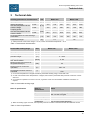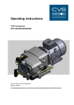
1
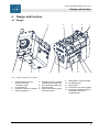
SiloKing 700 / 1100 Contents Operating instructions Screw compressor SiloKing 700 / 1100 Doc-ID: 5003-00/25.06.08/BA/EN Release: 06/2008 The operating instructions must be read by the machine operator and before start-up! © CVS engineering GmbH Grossmattstraße 14 D- 79618 Rheinfelden / Germany Phone: +49 (0) 7623 71741-0 Customer service: +49 (0) 7623 71741-31 E-mail: [email protected] Internet: www.cvs-eng.de Created by: alphatec Technische Dokumentationen Basler Str. 1 D-79639 Grenzach-Wyhlen Germany www.alphatecnet.de 2 Screw compressor SiloKing 700 / 1100 Contents 1 2 General....................................................................................4 1.1 Information regarding the operating instructions ...........4 1.2 Pictogram explanation ...................................................5 1.3 Limitation of liability........................................................6 1.4 Copyright protection.......................................................6 1.5 Spare parts ....................................................................7 1.6 Warranty conditions .......................................................7 1.7 Customer service ...........................................................7 Safety ......................................................................................8 2.1 Intended use ..................................................................8 2.2 Acceptance and monitoring ...........................................8 2.3 Operator's responsibility ................................................8 2.4 Operating personnel ......................................................9 2.4.1 Requirements .................................................9 2.5 Personal protective equipment ....................................10 2.6 Occupational safety and special dangers....................10 3 Technical data ......................................................................15 4 Design and function.............................................................17 5 6 7 8 4.1 Design..........................................................................17 4.2 Function .......................................................................18 4.3 Control and display elements ......................................18 Transport and storage.........................................................19 5.1 Safety notes for transport ............................................19 5.2 Transport......................................................................19 5.3 Storage ........................................................................19 Start-up and operation ........................................................20 6.1 Safety during start-up ..................................................20 6.2 Start-up ........................................................................20 6.3 Switching off.................................................................21 6.4 Inspections to be performed ........................................21 Maintenance .........................................................................22 7.1 Safety during maintenance work .................................22 7.2 Maintenance schedule.................................................22 7.3 Performance of maintenance work ..............................23 Malfunctions .........................................................................24 8.1 Safety...........................................................................24 8.2 Recommissioning after corrective action.....................24 8.3 Malfunction table..........................................................25 9 Spare parts ...........................................................................26 10 Decommissioning and disposal .........................................26 Index..............................................................................................27 3 Screw compressor SiloKing 700 / 1100 General 1 General 1.1 Information regarding the operating instructions These operating instructions provide important information on how to deal with the machine. Prerequisite for safe working is the observance of all specified safety notes and instructions. In addition, the local accident prevention regulations valid at the machine's area of application and general safety regulations have to be complied with. Carefully read the operating instructions before starting any work! They are a product component and must be kept in direct proximity of the machine, well accessible to the personnel at all times. When passing the machine on to third parties, the operating instructions must also be handed over. 4 Screw compressor SiloKing 700 / 1100 General 1.2 Pictogram explanation Warning notes Warning notes are characterised by pictograms in these operating instructions. The warning notes are preluded by signal words expressing the scale of the hazard. It is absolutely essential to observe the notes and to proceed with caution in order to prevent accidents as well as bodily injuries and property damage. DANGER! … points to an immediately dangerous situation, which will lead to death or serious injuries if it is not avoided. WARNING! … points to a potentially dangerous situation, which may lead to death or serious injuries if it is not avoided. ATTENTION! … points to a potentially dangerous situation, which may lead to minor or light injuries if it is not avoided. CAUTION! … points to a potentially dangerous situation, which may lead to property damage if it is not avoided. Hints and recommendations NOTE! … highlights useful hints and recommendations as well as information for an efficient and trouble-free operation. 5 Screw compressor SiloKing 700 / 1100 General 1.3 Limitation of liability All specifications and notes in these operating instructions were compiled with consideration to the valid standards and regulations, the state of the art as well as to our long-standing knowledge and experience. The manufacturer is not liable for damages caused by: Non-observance of the operating instructions Improper use Deployment of non-trained personnel Arbitrary modifications Technical changes Use of non-approved spare and wear parts The actual scope of supply may differ from the explanations and illustrations described in this manual in case of special designs, if additional order options are made use of, or due to latest technical changes. Incidentally, the responsibilities agreed upon in the delivery contract, the general terms and conditions as well as the manufacturer's conditions of delivery and the statutory provisions valid at the time of contract conclusion shall apply. Warranty The manufacturer guarantees the correct functioning of the applied process technology and the performance parameters identified. The warranty period commences on the date the machine is delivered to the customer. Components are exempted from the warranty and from claims for defects as far as wear and tear damage is concerned. 1.4 Copyright protection Surrendering the operating instructions to third parties without written permission of the manufacturer is not permitted. NOTE! Content details, texts, drawings, pictures and other illustrations are protected by copyright and are subject to industrial property rights. Any improper use shall be liable to prosecution. Any type and form of duplication – also of extracts – as well as the exploitation and/or communication of the contents are not permitted without the manufacturer's written declaration of consent. 6 Screw compressor SiloKing 700 / 1100 General 1.5 Spare parts WARNING! Risk of injury by incorrect spare parts! Incorrect or defective spare parts can result in damages, malfunctions or total failure and also impair safety. Therefore: – Use only the manufacturer's original spare parts. Procure spare parts from authorised dealers or directly from the manufacturer. Refer to page 2 for address. 1.6 Warranty conditions For warranty conditions refer to the "General Terms and Conditions". 1.7 Customer service Our customer service can be contacted for any technical advice. Information about the responsible contact person can be retrieved by telephone, fax, E-mail or via the Internet at any time, refer to manufacturer's address on page 2. 7 Screw compressor SiloKing 700 / 1100 Safety 2 Safety 2.1 Intended use The SiloKing 700 / 1100 is exclusively intended for the compression of filtered air. The machine has been developed for installation into a superordinate system. Only use machine for the intended use. All specifications in the operating instructions must be strictly adhered to (technical data, operating data, permissible working range), refer to chapter 3 in this regard. All types of claims due to damage arising from improper use are excluded. The operator alone shall be responsible for any damage arising from improper use. 2.2 Acceptance and monitoring The SiloKing is not subject to any acceptance and monitoring obligation. 2.3 Operator's responsibility The machine is used for industrial purposes. The operator of the machine is therefore subject to the legal obligations concerning occupational safety. The provisions valid at the place of installation as well as the safety and accident prevention regulations of the Institution for statutory accident insurance and prevention must be observed. The operator must in particular: inform himself on the valid industrial safety regulations. determine the additional hazards that arise from the special working conditions at the machine's place of installation by means of a hazard assessment. implement the necessary rules of conduct for operation of the machine at the place of installation by means of user instructions. check at regular intervals during the machine's entire period of use whether the user instructions correspond to the current state of the body of rules and regulations. adapt the operating instructions – if necessary – to the new regulations, standards, and operating conditions. clearly regulate the responsibilities for installing, operating, maintaining and cleaning the device. 8 Screw compressor SiloKing 700 / 1100 Safety ensure that all employees working on or with the machine have read and understood the operating instructions. In addition he must at regular intervals train the employees in how to deal with the machine and inform them about potential hazards. In addition, it is the operator's responsibility to ensure that: the machine is always in a technically perfect condition. the machine is maintained in accordance with specified maintenance intervals. all safety equipment is regularly checked for completeness and correct functioning. 2.4 Operating personnel 2.4.1 Requirements WARNING! Risk of injury in case of inadequate qualification! Improper handling can lead to considerable bodily injuries and property damage. Therefore: – Have any activities only carried out by the individuals designated for that purpose. The operating instructions specify the following qualification requirements for the different fields of activity: Instructed persons have been instructed during instructions provided by the operator with regard to the work assigned to them and possible hazards arising from improper conduct. Specialised staff is due to its technical training, knowledge and experience as well as due to its knowledge of the pertinent regulations able to carry out the work assigned to it and to independently recognise potential hazards. 9 Screw compressor SiloKing 700 / 1100 Safety 2.5 Personal protective equipment It is necessary to wear personal protective equipment when dealing with the machine so as to minimise health hazards. Before carrying out any work, properly don the necessary protective equipment such as gloves, safety goggles, etc. and wear during work. 2.6 Occupational safety and special dangers The remaining risks, which result from the hazard analysis, are specified in the following section. Observe the safety notes listed here and the warning notes in the other chapters of these instructions to reduce health hazards and to avoid dangerous situations. Danger pictograms on the device The relevant dangerous spots on the machine are identified by these pictograms: DANGER! General danger pictogram! … denotes general dangerous situations for individuals. Non-observance of the safety instructions can result in severe injuries or death. DANGER! Danger of burns! … denotes the presence of a hot surface. 10 Screw compressor SiloKing 700 / 1100 Safety Hazard notes and occupational safety For your own safety and that of the machine, the following information must be observed and complied with: Improper operation DANGER! Danger due to improper operation! – Only use machine in a perfect technical condition. Malfunctions that are relevant for safety have to be promptly eliminated. – Conversions of the machine are not permissible and can impair safety. – Before carrying out regular maintenance, cleaning and repair work, switch off power supply and secure machine against restarting (switch off drives). – Never bridge any safety equipment or put it out of operation. – Any work on the machine and/or on electrical equipment must be carried out by specialised staff. – Repair and maintenance work may only be carried out when the machine is stationary. For this, the machine must be secured against restarting! – The machine may not be under pressure or negative pressure while work is being carried out on it. Close shut-off valve on the vehicle side and vent the pipe between machine and shut-off valve or manually relieve excess pressure at safety valve. Observe pressure gauge indication! – The drive's protective equipment may only be removed when the machine is stationary and has to be correctly refitted after completion of work. – Only dismantle accidental contact protection if machine and pressure pipe have cooled down. – It is an environmental protection requirement that any liquids arising during maintenance work (e.g. oil) must be collected and disposed of in an environmentally compatible manner 11 Screw compressor SiloKing 700 / 1100 Safety Moving components WARNING! Risk of injury by moving components! Powered rotating components can cause the most serious injuries! Therefore during operation: – It is absolutely forbidden for individuals to stay in the hazard area or in the immediate vicinity! – Do not put safety devices and/or functions out of operation and do not render them inoperative or bypass them. – Never reach into open outlets and inlets or into running equipment. Before entering the hazard area: Compressed air – Switch off power supply and secure against restarting. – Wait for standstill of lagging components. – Wait for automatic dissipation and/or discharge of residual energies (compressed air). WARNING! Risk of injury due to compressed air! Pneumatic energies can cause the most serious injuries. In the case of damage to individual components, air can be discharged under high pressure and injure e.g. the eyes. Therefore: – Before starting any work, first depressurise pressurised components. Pay attention to accumulators. Accumulator pressure must also be completely relieved. Signposting WARNING! Risk of injury by illegible pictograms! Labels and signs can become dirty or unrecognisable in the course of time. Therefore: – Always keep safety, warning and operating instructions in a well legible condition. – Immediately replace damaged or obliterated signs or labels. 12 Screw compressor SiloKing 700 / 1100 Safety Improper transport DANGER! Danger by falling down or tilting of the machine! The weight of the machine may injure a person and cause serious bruising! Therefore: – Depending on the dead weight and size of the machine, use a pallet on which the machine can be moved by means of a fork lift. – For lifting the machine, use suitable lifting gear (slings, etc.) that is designed for the weight of the machine. – When putting the slings in position, take care to avoid putting stress on individual components. – Only use the provided attachment points with eye bolts. Start-up, operation WARNING! Risk of injury due to improper start-up and operation Improper start-up and operation can lead to serious bodily injuries or property damage. Therefore: – Have all work during initial operation exclusively performed by the manufacturer's employees or by his authorised representatives or by trained personnel. – Start-up and operation may only be performed by adequately qualified personnel that has been authorised and instructed by the operator. – Before the start of any work, ensure that all covers and protective devices are correctly installed and function correctly. – Never override any protective equipment during operation. – Pay attention to tidiness and cleanliness in the working area! Loosely stacked or scattered components and tools are accident sources. 13 Screw compressor SiloKing 700 / 1100 Safety Maintenance and trouble shooting WARNING! Risk of injury due to improper maintenance and trouble shooting! Improper maintenance and trouble shooting can lead to serious bodily injuries or property damage. Therefore: – Maintenance work and trouble shooting work may only be carried out by adequately qualified and instructed personnel. – Secure machine against restarting, switch off drives! – Before starting any work, provide for sufficient space and freedom of movement during assembly. – Pay attention to tidiness and cleanliness in the assembly area! Loosely stacked or scattered components and tools are accident sources. If components must be replaced: – Pay attention to correct installation of spare parts. – Properly reassemble all fastening elements. – Observe screw tightening torques. – Before restarting, ensure that all covers and protective devices are correctly installed and function correctly. – After completion of maintenance work and trouble shooting, check correct functioning of safety equipment. 14 Screw compressor SiloKing 700 / 1100 Technical data 3 Technical data SiloKing performance characteristics 1) Unit Input speed [rpm] Intake volume flow at a final overpressure at the pressure flange 0.0 bar Coupling power at a final overpressure at the pressure flange: 0.0 bar [m3/h] 2.5 bar Model 700 Model 1100 2400 3000 3600 2400 3000 3600 420 540 650 675 850 1050 376 471 587 581 756 962 11.0 13.5 16.0 19.0 22.5 26.5 22.5 31.5 38.0 37.0 49.0 59.5 185 181 179 185 181 179 [kW] 2.5 bar Final temperature at nominal design parameters [°C] Compressor weight [kg] 117 125 1) Intake pressure at the suction flange = 1.0 bar, suction and ambient temperature = 20 °C Table 1: Performance characteristics Permissible working range Unit Input speed [rpm] 2400…3600 [°C] −10…+40 [m] 0…1000 Negative pressure suction side (e.g. due to soiling) [mbar] 0…65 Maximum final overpressure at the pressure flange 2) [bar] 2.5 Running time in continuous operation 3) [h] max. 3.0 Permissible inclination from the horizontal [°] ±10 Suction temperature Geodetic height 1) 1) Model 700 Model 1100 1) For suction temperatures or heights outside the permissible working range, consult with CVS. 2) In case of increased suction temperatures or heights, the maximum permissible final pressure is reduced. Consult with CVS. 3) For continuous operation in excess of 3 hours, a gearbox cooler must be installed. Installation instructions on request. Table 2: Permissible working range Gear oil specification Gear oil specification Value Specification API CD/SF or higher, respectively MIL L-2104C or higher SAE viscosity class Gear oil quantity Oil pressure 1) 10W40 or 15W40 8 litres min. 0.5 bar (excess pressure) 1) When connecting a gear oil cooler, the oil quantity must be increased commensurate with the additional volume. Table 3: Gear oil specification 15 Screw compressor SiloKing 700 / 1100 Technical data Types of gear oil Brand CVS 1) Type of oil CVS-LUB 1000 ARAL Multi Turboral SAE 15W40 DEA Cronos Super DX SAE 15W40 ESSO Essolube XT 201 SAE 15W40 SHELL Universal Engine Oil SAE 15W40 FUCHS Titan Universal HD SAE 15W40 BP Vanellus C5 Global SAE 15W40 1) You may purchase the high performance oil CVS-LUB 1000 from CVS. Using this special oil doubles the oil change interval to 1 year or 1000 operating hours respectively and extends the warranty period to 2 years.. Table 4: Types of gear oil 16 Screw compressor SiloKing 700 / 1100 Design and function 4 Design and function 4.1 Design 6 7 8 7 9 4 3 2 1 10 1 11 5 12 13 Fig. 1: View of compressor and details 1 2 3 4 Vertical fastening screw thread (4 each per compressor side) Air outlet flange Attachment point for transport Rating plate gear oil 5 6 7 8 Oil filler neck cap / gearbox ventilation with oil dip stick Drive shaft with feather key Oil drain screw Horizontal fastening screw thread (4 pieces) 9 10 11 12 13 Rating plate compressor data Air intake flange Gear oil filter Connection oil pressure gauge Connection pressure gauge or temperature sensor for compressed air 17 Screw compressor SiloKing 700 / 1100 Design and function 4.2 Function Functional principle Cleaned air is taken in via the air intake flange. Two screw rotors compress the air completely dry. The rotors are running contactfree both in relation to each other and to the casing. They are kept apart by a synchronising gearbox. The compressed gas reaches the consumer via the air outlet flange. Lubrication Bearing and gearbox are supplied with gear oil via an oil filter by means of an integrated oil pump. Cooling The heat is dissipated to the ambient air via the casing surface. Sense of rotation The drive shaft's sense of rotation is clockwise when looking onto the drive shaft. Drives The machine is driven via coupling, V-belt or articulated shaft. For a drive via articulated shaft and for compressor installation within the chassis, CVS offers an adapter gear with a transmission ratio of 1:2. 4.3 Control and display elements Depending on the installation location, different display elements such as pressure gauge, temperature gauge and negative pressure display are available. 18 Screw compressor SiloKing 700 / 1100 Transport and storage 5 Transport and storage 5.1 Safety notes for transport Refer to chapter 2.6 Safety! 5.2 Transport The machine that is fastened on a baseplate must be transported with a fork lift or suitable straps. The lifting gear must be designed for the weight of the machine. For future transports: Seal all open connections with protective caps (prevents penetration of dirt and water) Secure against vibrations Drain gear oil Securely fasten the machine prior to transport (e.g. screw it onto a pallet) Transport and put down machine with a fork lift or secure with straps and lift with suitable lifting gear. 5.3 Storage Storage of packages Store packages under the following conditions: Do not store outdoors. Store dry and dust free. Do not expose to aggressive media. Protect against solar irradiation Avoid mechanical vibrations. Storage temperature: −10 to +60 °C Relative humidity: max. 95%, non-condensing If storage lasts longer than 3 months, regularly check the general condition of all parts and of the packaging. On machines intended for export (overseas), bags with desiccant are placed into the inlets and outlets. These bags keep moisture away from the machine's workspace. Remove bags before suction and pressure line are connected. 19 Screw compressor SiloKing 700 / 1100 Start-up and operation 6 Start-up and operation 6.1 Safety during start-up Refer to chapter 2.6 Safety! 6.2 Start-up CAUTION! The machine must always be supplied with sufficient oil. Check oil level with screwed-in oil dip stick and top up with oil if necessary. Refer to rating plate oil on the compressor or Table 3. Inspection prior to initial start-up The following points must be checked prior to initial start-up: Compressor for transport damage Correctness of data on the rating plate Conduits for free passage and leak tightness Screw connections for tightness Drive's sense of rotation by briefly switching it on and off (correct sense of rotation: clockwise when looking onto the drive shaft, see sense of rotation arrow) Oil level by means of oil dip stick Direction of installation and function of non-return valve Safety valve function Accidental contact protection function Suction and pressure lines must be installed Start-up Pay attention to permissible compressor inclination (refer to Table 1) Open shut-off devices Switch on drive (engage gently) Adjust input speed Inspections during operation During operation, the operator has to check the following data every 20 minutes: Input speed (refer to Table 2) Final overpressure (refer to Table 2) Gear oil pressure (refer to Table 3) 20 Screw compressor SiloKing 700 / 1100 Start-up and operation 6.3 Switching off Switch off compressor as follows: Switch off drive. Close shut-off valves.Drain condensate e.g. when using a compressed air after cooler. 6.4 Inspections to be performed Gear oil inspection Check the gear oil level with the screwed-in oil dip stick and top up with oil if necessary. Non-return valve inspection The non-return valve is maintenance free, but is subject to wear like any other moving part. We recommend a visual inspection every 3 months. In this connection, the non-return valve must be dismantled, cleaned, freed of deposits and checked for freedom of motion. Safety valve inspection The safety valve is no regulating device! The operational capability must be checked on start-up and later at weekly intervals. The safety valve must be secured against misadjustment. Blocking or manipulating the safety valve can have penal consequences if it gives rise to an accident. Any warranty claims shall also be forfeited in such a case. The nominal opening pressure may not exceed the maximum permissible final overpressure (refer to Table 2) or the permissible system pressure, provided the latter is lower. 21 Screw compressor SiloKing 700 / 1100 Maintenance 7 Maintenance 7.1 Safety during maintenance work See chapter 2.6 Safety! Personal protective equipment The following must be worn during all maintenance work: Safety working clothing Protective gloves Safety shoes Safety goggles Environmental protection Observe the following information with regard to environmental protection during maintenance: Remove emerging, used or excessive grease at all lubricating points that are manually supplied with lubricant and dispose of in accordance with valid local regulations. Collect exchanged oil in suitable containers and dispose of in accordance with valid local regulations. 7.2 Maintenance schedule The following describes the maintenance work that is necessary for an optimum, trouble-free operation. Maintenance intervals must be observed. If increased wear of individual components or functional groups is determined during regular inspections, the operator has to reduce the required maintenance intervals on the basis of the actual signs of wear. Changes compared to normal operation (increased power consumption, temperatures, vibrations, noises, etc. or response of monitoring systems) lead to the assumption that the functions are impaired. These then have to be subjected to an inspection by specialised staff. In case of queries regarding the maintenance work and intervals: contact the manufacturer (service address Æ page 2). For maintenance schedule refer to next page. 22 Screw compressor SiloKing 700 / 1100 Maintenance Maintenance schedule Interval Weekly quarterly half-yearly or every 500 h Maintenance work To be carried out by Check and clean compressor (refer to chapter 8.3) Check screw connections Check gear oil level (refer to Table 3) Check air filter's degree of soiling (refer to Table 2) Operator Check V-belt tension * Check connection to drive (coupling, V-belt) * Check safety valve * Clean compressed air after cooler or oil cooler, clean cooling air fins * Check non-return valve (refer to chapter 8.3) Carry out gear oil change (refer to chapter 8.3) Specialised staff Oil filter change (refer to chapter 8.3) * Observe manufacturer's recommendations Table 5: Maintenance schedule 7.3 Performance of maintenance work Cleaning the compressor Observe the following when cleaning the compressor: 1. 2. Switch off compressor and secure against restarting. Remove soiling. Do not use aggressive cleaning agents. No water may penetrate the compressor. Caution when using a high-pressure cleaner. After wet cleaning, warm up the compressor for a few minutes. Gear oil change Open oil drain screws (Fig. 1, drain oil. Dismantle oil filter with the aid of a strap wrench. For installation, lightly grease the new oil filter on top of the seal and tighten hand-tight. Close oil drain screws and fill in oil. (refer to Table 3). Safety valve inspection The safety valve must be secured against misadjustment. Functional testing is carried out by actuating the manual ventilation with the machine running. Action after lengthy standstill During a lengthier standstill, we recommend to put the compressor into operation every 4 weeks for approx. 15 minutes. 23 Screw compressor SiloKing 700 / 1100 Malfunctions 8 Malfunctions This chapter describes possible causes of malfunctions and trouble shooting tasks. Reduce the maintenance intervals if similar malfunctions occur repeatedly due to above-average intensive use so intervals correspond to the actual load. Contact the manufacturer in case of malfunctions that cannot be repaired with the aid of the following information (Æ p. 2)! 8.1 Safety Refer to chapter 2.6 Safety! The trouble shooting work described at this point can be carried out by the operator, unless otherwise indicated. Personnel Some work may only be carried out by specially trained specialised staff or exclusively by the manufacturer himself. This is specifically pointed out in the description of the individual malfunctions. Only electrical specialists may carry out work on the electrical system. Components and parts may only be replaced by specialised staff. Personal protective equipment Refer to chapter 7.1 Environmental protection Refer to chapter 7.1 Conduct in the case of malfunctions The following basically applies: 1. Immediately switch off the compressor in case of malfunctions representing an immediate danger for individuals or material assets. 2. Switch of all power supplies and secure against restarting. 3. Inform person in charge at the place of installation. 4. Depending on the type of malfunction, have the cause determined and eliminated by responsible and authorised specialised personnel. 8.2 Recommissioning after corrective action After corrective action or trouble shooting: 24 1. Ensure that nobody is staying in the hazard area. 2. Start in accordance with the instructions in chapter „start-up“. Screw compressor SiloKing 700 / 1100 Malfunctions 8.3 Malfunction table Malfunction: Possible cause Corrective action Execution Flow rate too low Air filter soiled Clean or replace filter cartridge Operator Pressure line leaky Eliminate leakage Specialised staff Speed too low Correct speed (refer to Table 2) Operator Misalignment vis-à-vis drive Align compressor Specialised staff Bearing defective Lack of lubricating oil Replace bearing Top up with oil (refer to Table 3) Manufacturer Operator Unsuitable lubricating oil Oil change (refer to Table 3) Operator Wrong speed Correct speed (refer to Table 2) Operator Foreign matter in the machine Clean machine Specialised staff Final pressure too high Adhere to permissible final pressure (refer to Table 1) Operator Head loss in suction system too high Clean or replace filter cartridge Operator Final overpressure too high Adhere to maximum final overpressure Specialised staff (refer to Table 1) Check pressure line for clogging Wrong speed Correct speed (refer to Table 2) Operator Pressure gauge defective Replace pressure gauge Specialised staff Leakage in the pressure line Eliminate leakage Specialised staff Wrong speed Correct speed (refer to Table 2) Operator Pressure gauge defective Replace pressure gauge Specialised staff Correct speed (refer to Table 2) Operator Adhere to permissible final pressure (refer to Table 1) Operator Shut-off valve not fully open Fully open shut-off valve Operator Pressure line clogged Eliminate clogging Operator Pressure gauge defective Replace pressure gauge Specialised staff Lack of lubricating oil Top up with oil (refer to Table 3) Operator Max. inclination exceeded Correct inclination (refer to Table 1) Operator Speed too low Correct speed (refer to Table 2) Operator Oil filter soiled Replace oil filter Operator Unsuitable lubricating oil Oil change (refer to Table 3) Operator Lack of lubricating oil Top up with oil (refer to Table 3) Operator Max. inclination exceeded Correct inclination Operator Unsuitable lubricating oil Oil change (refer to Table 3) Operator Abnormal noise emission Compressed air temperature too high Operating pressure is not attained Power requirement Speed too high too high Final pressure too high Safety valve blows off Oil pressure too low Oil pressure fluctuates heavily Table 6: Malfunction table 25 Screw compressor SiloKing 700 / 1100 Spare parts 9 Spare parts Customer service In case of queries regarding the product, spare part orders, repairs, replacement machines and dispatch of fitters, please contact our customer service: Phone.: +49 (0) 7623 71741-31 10 Decommissioning and disposal A compressor that is no longer usable should not be recycled as complete unit, but disassembled into individual components and recycled according to material types. Non-recyclable materials have to be disposed of in an environmentally compatible manner. Prior to decommissioning and disposal of the machine, it must be completely separated from the surrounding units. The disassembly and disposal of the machine may only be carried out by specialised staff. The machine has to be disposed of in accordance with the respective country-specific regulations. 26 Screw compressor SiloKing 700 / 1100 Index Index A M Acceptance...........................................................8 Maintenance .......................................................22 C Maintenance schedule........................................22 Check safety valve .............................................23 Maintenance work...............................................23 Cleaning Malfunction table.................................................25 compressor .....................................................23 Malfunctions........................................................24 Components, moving..........................................12 O Compressed air ..................................................12 Occupational safety ............................................10 Contact person .....................................................7 Operating instructions...........................................4 Copyright protection .............................................6 Operating personnel .............................................9 Customer service..................................................7 Operator................................................................8 D P Danger of burns..................................................10 Packaging ...........................................................19 Danger pictogram ...............................................10 Personnel Danger pictograms .............................................10 Trouble shooting .............................................24 Dangers ..............................................................10 Pictograms in the operating instructions...............5 Design.................................................................17 Pneumatics .........................................................12 Design and function............................................17 Protective equipment ..........................................10 Disposal ..............................................................26 Maintenance....................................................22 F R Function ..............................................................18 Recommissioning ...............................................24 G S Gear oil change ..................................................23 Safety....................................................................8 Gear oil specification ..........................................15 Signposting .........................................................12 I Spare parts .....................................................7, 26 Improper operation .............................................11 Specialised staff....................................................9 Inspection Start-up ...............................................................20 during operation ..............................................20 Storage ...............................................................19 gear oil ............................................................21 Switching off .......................................................21 non-return valve ..............................................21 T prior to initial start-up ......................................20 Technical data ....................................................15 safety valve .....................................................21 Transport.............................................................19 Instructions ...........................................................9 Types of gear oil .................................................16 Intended use.........................................................8 L W Warranty ...........................................................6, 7 Lengthy standstill................................................23 Liability..................................................................6 27