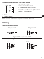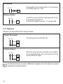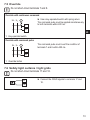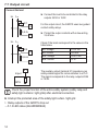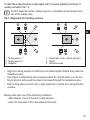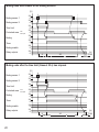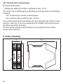
1
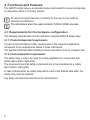
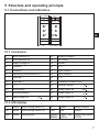
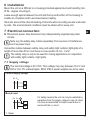
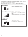
Original operating instructions
Safety relay
with relay outputs
and muting function
704576 / 02
01 / 2014
G2001S
UK
Contents
1 Preliminary note���������������������������������������������������������������������������������������������������4
1.1 Symbols used������������������������������������������������������������������������������������������������4
1.2 Warning signs used���������������������������������������������������������������������������������������4
2 Safety instructions�����������������������������������������������������������������������������������������������5
3 Items supplied�����������������������������������������������������������������������������������������������������5
4 Functions and features����������������������������������������������������������������������������������������6
4.1 Requirements for the hardware configuration�����������������������������������������������6
4.1.1 Product-independent requirements������������������������������������������������������6
4.1.2 Product-dependent requirements���������������������������������������������������������6
5 Structure and operating principle�������������������������������������������������������������������������7
5.1 Connections and indicators���������������������������������������������������������������������������7
5.1.1 Connections������������������������������������������������������������������������������������������7
5.1.2 LED displays�����������������������������������������������������������������������������������������7
5.1.3 LED states��������������������������������������������������������������������������������������������8
6 Installation�����������������������������������������������������������������������������������������������������������9
7 Electrical connection��������������������������������������������������������������������������������������������9
7.1 Supply voltage�����������������������������������������������������������������������������������������������9
7.2 Automatic or manual operation / feedback contacts������������������������������������10
7.3 Muting���������������������������������������������������������������������������������������������������������� 11
7.4 Timeout��������������������������������������������������������������������������������������������������������12
7.5 Override�������������������������������������������������������������������������������������������������������13
7.6 Safety light curtains / light grids�������������������������������������������������������������������13
7.7 Output circuit�����������������������������������������������������������������������������������������������14
7.8 Overview������������������������������������������������������������������������������������������������������15
8 Operating modes�����������������������������������������������������������������������������������������������17
8.1 Automatic operation�������������������������������������������������������������������������������������17
8.2 Manual operation�����������������������������������������������������������������������������������������17
8.2.1 Restart������������������������������������������������������������������������������������������������17
8.3 K1/K2 feedback contacts ����������������������������������������������������������������������������17
8.4 Muting����������������������������������������������������������������������������������������������������������18
8.4.1 Alignment of 2 muting sensors�����������������������������������������������������������19
8.5 Override�������������������������������������������������������������������������������������������������������21
8.5.1 Override with continuous command���������������������������������������������������21
2
8.5.2 Override with command pulse������������������������������������������������������������22
9 Scale drawing����������������������������������������������������������������������������������������������������22
10 Technical data��������������������������������������������������������������������������������������������������23
11 Fault diagnoses �����������������������������������������������������������������������������������������������24
12 Maintenance, repair and disposal��������������������������������������������������������������������25
13 Tests/approvals������������������������������������������������������������������������������������������������25
14 Terms and abbreviations����������������������������������������������������������������������������������26
3
UK
1 Preliminary note
The instructions are part of the unit. They are intended for authorised persons
according to the EMC and low voltage directives and safety regulations.
The instructions contain information about the correct handling of the product.
Read the instructions before use to familiarise yourself with operating conditions,
installation and operation.
Adhere to the safety instructions.
1.1 Symbols used
► Instruction
> Reaction, result
→ Cross-reference
LED off
LED on
LED flashes
Important note
Non-compliance can result in malfunctions or interference.
Information
Supplementary note.
1.2 Warning signs used
WARNING
Warning of serious personal injury.
Death or serious irreversible injuries may result.
2 Safety instructions
• Follow the operating instructions.
• In case of non-observance of instructions or standards, especially when tampering with and/or modifying the unit, any liability and warranty is excluded.
• The unit must be installed, connected and put into operation by a qualified
electrician trained in safety technology.
• The applicable technical standards for the corresponding application must be
complied with.
4
• For the installation the standards EN 60204, EN 999 and ISO 13855 have to be
adhered to (the response times of all safety components have to be observed).
• In case of malfunction of the unit please contact the manufacturer. Tampering
with the unit is not allowed.
• Disconnect the unit externally before handling it. Also disconnect any independently supplied relay load circuits.
• After setup the system has to be subjected to a complete function check.
• Use the unit only in specified environmental conditions (→ 10 Technical data).
In case of special operating conditions please contact the manufacturer.
UK
WARNING
In case of improper handling of the product, the safety and physical integrity of operators and machinery cannot be guaranteed.
Death or serious irreversible injuries may result.
►► Observe all notes on installation and handling in these instructions.
►► The safety relay must only be used under the specified operating conditions
and in accordance with use as prescribed below.
3 Items supplied
• 1 G2001S safety relay
• 1 copy of the operating instructions safety relay, reference 704576.
If one of the above-mentioned components is missing or damaged, please contact
one of the ifm branch offices.
5
4 Functions and features
The G2001S safety relay is a redundant system and suited for use as muting relay
in conjunction with 2 or 4 muting sensors.
ifm electronic gmbh assumes no liability for the use of units made by
external manufacturers.
The safe state is when the output contacts (12/22 or 23/24) are open.
4.1 Requirements for the hardware configuration
The following requirements must be met when using the G2001S safety relay:
4.1.1 Product-independent requirements
It must be ensured that the safety requirements of the respective application
correspond to the requirements stated in these instructions.
The specified technical data indicated in these instructions must be complied with.
4.1.2 Product-dependent requirements
The safety relay is only to be used for muting applications in conjunction with
safety light curtains / light grids.
The response times of all safety components are to be considered (e.g. safety
light curtains / light grids).
In case of faults within the safety relay which result in the defined safe state, the
safety relay must be replaced.
Any faulty unit should be returned to the manufacturer.
6
5 Structure and operating principle
5.1 Connections and indicators
1
4
2
5
3
6
13
15
16 17 18
S1
IN
S2
FAIL
MUT.
GUARD
BREAK
7 8 9
10 11 12
UK
19 20 21
22 23 24
5.1.1 Connections
1
2
3
4
5
6
7
8
9
Muting sensor S1
Muting sensor S2
Supply voltage L+
Timeout 1
Timeout 2
Operating mode MAN/AUTO
Override 1
Override 2
n. c.
13
14
15
16
17
18
19
20
21
Supply voltage LPE (GND)
Restart
n. c.
Input OSSD 1
Input OSSD 2
n. c.
Feedback contact K1/K2
Auxiliary output
10
Muting lamp
22
Relay output R2
11
Muting activation
23
Relay output R1
12
Relay output R2
24
Relay output R1
5.1.2 LED displays
S1
yellow status muting sensor S1
S2
yellow status muting sensor S2
MUT. yellow muting status
IN
FAIL
GUARD
BREAK
green
red
green / red /
yellow
status OSSDs
failure
status relay output
R1/R2
7
5.1.3 LED states
Description
S1
IN
S2
FAIL
MUT. GUARD
BREAK
LED
S1
S2
MUT.
yellow
yellow
yellow
/
/
Switch-on test
Object detected
No object detected
Muting active
Override request
Description
S1
IN
S2
FAIL
MUT. GUARD
BREAK
Switch-on test
Protected area interrupted,
relay outputs deactivated
Protected area clear,
relay output deactivated,
waiting for restart
Protected area clear,
relay outputs activated
8
LED
IN
FAIL
green
red
GUARD/BREAK
red
yellow
green
6 Installation
Mount the unit on a DIN rail in a housing protected against dust and humidity (min.
IP 54 - degree of soiling 2).
Leave enough space between the unit and the top and bottom of the housing to
enable air circulation and to avoid excessive heating.
Take into account the internal heating of all units when mounting several units side
by side. The environmental conditions must be observed for every unit.
7 Electrical connection
UK
►► Disconnect power. Also disconnect any independently supplied relay load
circuits.
Note: Lay the safety relay cables separately from sources of interference
such as power lines.
Connection cables between safety relay and safety light curtains /light grids of a
length of more than 50 m must have a cross-section of min. 1 mm².
The safety relay is only to be used for muting applications in conjunction
with safety light curtains / light grids.
7.1 Supply voltage
The nominal voltage is 24 V DC. This voltage may vary between 19.2 V and
28.8 V incl. 5% residual ripple. SELV /PELV power supplies are to be used.
Connect supply voltage
L+ L
3
13
Manual reset
L+ L
3
13
For safety reasons the unit can only be restarted by
separation from the supply voltage in case of a fault.
It is thus recommended to install a reset button in
series with the L+ circuit.
1: Reset
9
After power on or a reset the unit carries out self diagnostic functions. After this
self diagnosis the unit is ready for operation.
7.2 Automatic or manual operation / feedback contacts
Automatic operation
Automatic activation without monitoring.
L+ L
15
6
Automatic operation with monitoring of the feedback contacts
L+ L
15
6
Release is made when the feedback contacts are
closed.
Consider the current flowing through the feedback
contacts (→ 10 Technical data).
20
1: Feedback contacts
Manual operation
L+ L
15
6
1: Restart
10
Activate the relay outputs:
►► Press and release restart (> 100 ms).
Manual operation with monitoring of the feedback contacts
Activate the relay outputs:
The feedback contacts are closed
►► Press and release restart (> 100 ms).
L+ L
15
6
Consider the current flowing through the feedback
contacts (→ 10 Technical data).
20
1: Restart
2: Feedback contacts
UK
►► If no feedback contacts are used, connect terminals 20 and 21.
7.3 Muting
Connection of 2 muting sensors
Muting sensor S1
L+ L
Muting sensor S2
L+ L
1
2
Alignment of the muting sensors → 8.4.1
Connection of 4 muting sensors
L+ L
L+ L
1
2
11
Muting lamp
L+ L
10
Prerequisite for the muting function is the connection
of a muting lamp (0,5...5 W).
Muting activation
L+ L
11
To start the muting function a high signal (24 V) has
to be applied to terminal 11.
A continuous signal or a pulse > 1 s can be used.
7.4 Timeout
Timeout is a time limit of the muting function.
Timeout 30 seconds
The muting function ends after 30 s.
L+ L
4
5
Unlimited timeout
L+ L
4
When the muting function has started it is available
for an unlimited period of time as long as the muting
sensors detect an object.
5
If unlimited timeout is used, additional measures are to be taken to avoid a
permanent muting function.
12
7.5 Override
Do not short-circuit terminals 7 and 8.
Override with continuous command
L+ L
7
►► Use a key-operated switch with spring return.
The command pulse must be applied simultaneously
to both terminals within 400 ms.
8
UK
1: Key-operated switch
Override with command pulse
L+ L
7
The command pulse must invert the condition of
terminals 7 and 8 within 400 ms.
8
1: Override button
7.6 Safety light curtains / light grids
Do not short-circuit terminals 17 and 18.
17
18
►► Connect the OSSD signals to terminals 17 and
18.
13
7.7 Output circuit
Connect the load
►► Connect the load to be controlled to the relay
outputs 23/24 or 12/22.
L+ L
K1
12
For the output circuit, the G2001S uses two guided
contact safety relays.
22
►► Protect the output contacts with a slow-acting
3,6 A fuse.
24
Check if the loads correspond to the values in the
table below.
Min. voltage
> 18 V DC
Min. current
> 20 mA
Max. voltage
< 250 V AC
Max. current
<2A
3,6 A
L+ L
K2
3,6 A
23
21
Input
SPS
The auxiliary output (terminal 21) provides a non
safety-related signal for communication to a PLC.
The signal corresponds to the relay outputs 23/24
or 12/22.
Check the proper function of the entire safety system (safety relay and
safety light curtains / light grids) after electrical connection.
►► Interrupt the protected area of the safety light curtain / light grid
>> Relay outputs of the G2001S drop out
→ 5.1.3 LED states (GUARD/BREAK)
14
7.8 Overview
Automatic operation with monitoring of the feedback contacts and timeout 30 s
L+ L
1 Sensor 1
0 V DC
13
2 Sensor 2
PE
14
3 24 V DC
Restart
15
4 Timeout 1
n. c.
16
5 Timeout 2
Input OSSD 1
17
6 MAN/AUTO
Input OSSD 2
18
7 Override 1
n. c.
19
8 Override 2
K1/K2 feedback
20
9 n. c.
Auxiliary output
21
10 Muting lamp
22
11 Muting enable
23
12
24
K1
UK
*)
K2
1: K1/K2 feedback contacts
*) If no feedback contacts are used, connect terminals 20 and 21.
15
Manual operation with monitoring of the feedback contacts and timeout 30 s
L+ L
1 Sensor 1
0 V DC
13
2 Sensor 2
PE
14
3 24 V DC
Restart
15
4 Timeout 1
n. c.
16
5 Timeout 2
Input OSSD 1
17
6 MAN/AUTO
Input OSSD 2
18
7 Override 1
n. c.
19
8 Override 2
K1/K2 feedback
9 n. c.
20 *)
Auxiliary output 21
10 Muting lamp
22
11 Muting enable
23
12
24
K1
1: K1/K2 feedback contacts
K2
2: Restart button
*) If no feedback contacts are used, connect terminals 20 and 21.
16
8 Operating modes
After new installation or change of the operating mode check the function of
the entire safety system (safety relay and safety light curtains / light grids).
8.1 Automatic operation
If the safety relay is used in the automatic mode, monitored start is not possible.
The safety light curtains / light grids automatically return to operation if the protected area is clear, the relay outputs (OSSDs) are activated.
Verify if this is compatible with your machine.
UK
In the automatic mode the relay 1 and relay 2 outputs follow the status of the
safety light curtains / light grids:
Protected area clear
Protected area interrupted
Relay outputs = active logic "1"
Relay outputs = deactived logic "0"
8.2 Manual operation
Operation in the manual mode is always necessary when passage to a hazardous area is to be monitored (persons can be present in the hazardous area after
accessing the protected area without being detected).
The relay 1 and relay 2 outputs become active when the protected area is clear
and restart is activated via a restart button or via a respective pulse (> 100 ms) on
the input of terminal 15.
If the safety light curtains / light grids are activated by a person or an object, a
restart is always necessary for the release.
8.2.1 Restart
The restart button has to be outside the hazardous area It has to be installed so
that the hazardous area and access can be clearly seen. It must not be possible to
activate the restart button from within the hazardous area.
The restart time of the safety relay is 100 ms. Also take into account the restart
times of the external contactors.
17
8.3 K1/K2 feedback contacts
External contactors can be integrated into the automatic or manual operation.
They must be connected to terminal 20 (K1/K2 feedback contact).
For loads of voltages and currents higher than those indicated in the following
table external contactors or auxiliary relays should be used in accordance with the
loads to be switched. Safety elements with positively guided contacts are to be
used.
Min. voltage
Min. current
Max. voltage
Max. current
≥ 18 V DC
≥ 20 mA
≤ 250 V AC
≤2A
If no external contactors are used, the terminals 20 (K1/K2 feedback contact) and
21 (auxiliary output) must be interconnected.
The auxiliary contacts of K1 and K2 must be able to switch a current of 20 mA and
a voltage of 24 V DC.
Suitable interference suppressors on the coil end of K1 and K2 prolong the life of
the internal relays.
8.4 Muting
Muting is the temporary suspension of the protective function of safety light curtains / light grids to transport objects through a hazardous area as planned. The
muting sensors detect objects before they enter the protected area and enable a
distinction between man and material after correct optical alignment.
Check if this function is compatible with the risk analysis of your machine
and if additional measures have to be taken.
The following components are necessary for the muting function:
-- G2001S safety relay
-- safety light curtain / safety light grid
-- 2 or 4 muting sensors
-- muting lamp (0,5...5 W)
18
To start the muting function a high signal (24 V) must be applied to terminal 11
(muting activation) for 1 s.
Correct alignment of the muting sensors is imperative for the proper function of the safety relay.
8.4.1 Alignment of 2 muting sensors
UK
1: Muting sensor 1
2: Muting sensor 2
3: Reflector
4: Safety light curtain / safety light grid
5: Object
6: Hazardous area
• Align the muting sensors so that they can detect objects before they enter the
hazardous area.
• If an object is detected by both muting sensors S1 and S2 within 4 s, the muting function is active and the object can travel through the hazardous area.
• Both muting sensors must carry a high signal (24 V) while the muting function
is active.
Muting ends with one of the following conditions:
-- after release of one of the two muting sensors
-- when the time limit of 30 s has elapsed (timeout)
19
Muting ends after release of the muting sensors
[V]
24
0
24
0
Muting sensor 1
Muting sensor 2
Time limit
Protected area
clear
interrupted
24
0
24
0
24
0
24
0
Muting
Timer
24
0
24
0
Muting enable
Relay outputs
4
30
[s]
0,02
Muting ends after the time limit (timeout 30 s) has elapsed
[V]
24
0
24
0
Muting sensor 1
Muting sensor 2
Time limit
Protected area
Muting
Timer
Muting enable
Relay outputs
20
clear
interrupted
24
0
24
0
24
0
24
0
24
0
24
0
4
30
[s]
0,02
8.5 Override
Override means suspension of the safety function. It ensures a controlled restart
to transport jammed material out of the protected area.
WARNING
During the whole override function access to the hazardous area is not
protected by the safety light curtains / light grids.
Death or serious irreversible injuries may result.
►► Mind the dangers in the hazardous area.
UK
When the override function is active, the OSSD outputs of the safety light curtains
/ light grids are inactive and/or at least one muting sensor detects an object.
The MUT. LED lights during the whole override function (→ 5.1.2 LED displays)
Regularly check the function of the LED displays.
The following types of override can be configured:
-- override with continuous command
-- override with command pulse
8.5.1 Override with continuous command
►► Activate key-operated switch
>> Bridging the safety light curtains / light grids for max. 15 min.
The override function ends with the following conditions:
-- key-operated switch activated again.
-- 15 min. have elapsed.
-- protected area clear and muting sensors free.
The GUARD function is activated without further commands.
21
8.5.2 Override with command pulse
►► Press override button
>> Bridging the safety light curtains / light grids for max. 15 min.
The function can be started again by activating the override button at the following
conditions:
-- max. 30 subsequent override command pulses
-- max. total time of the override function = 60 min.
The override function ends automatically with clear protected area and free muting
sensors or when the 15 min have elapsed and the GUARD function will be activated without any further command.
The timer for the override command pulses and the total time of the override
function will be reset to 0.
9 Scale drawing
114,5
99
35
LEDs
22
10 Technical data
G2001S
Safety relay with relay outputs
Meets the requirements of:
EN ISO 13849-1 (2008) category 4 PL e, SIL 3 (IEC 61508), SILCL 3 (IEC 62061)
Electrical design
Output function
relay
2 safety-related normally open contacts (floating
contacts, 2 A / 250 V);
1 signal output (PNP, 100 mA (24V))
24 V DC (19.2...28.8)
6 A / 250 V AC / 24 V DC ( ≥ 10 mA)
*) no
UK
Operating voltage
Contact rating
Short-circuit protection / overload
protection
Current consumption
208 mA (24 V)
Safety light curtains / light grids to 1 (with OSSD outputs)
be connected
Input muting sensors
2 sensors (24 V DC, PNP, dark-on mode)
Input muting activation
24 V DC, PNP
Output muting lamp
24 V DC / 0,5...5 W
Power-on delay time
< 12 s
Response time on safety request
20 ms
Min. load current of the feedback
20 mA (24 V)
contacts
Current rating auxiliary output
max. 100 mA (20 °C)
(terminal 21)
Ambient temperature
0...55°C
Protection rating
IP 20
Housing materials
PA
Mission Time (TM)
175200 h
Safety-related reliability PFH
7,0 -9 / h
100 years
MTTFd
DC / CCF / Cat.
96 % / 80 % / 4
Switching operations
800.000 (2 A (230 V AC) / 0,5 A (24 V DC))
*) The contacts are to be protected by means of fuses with a nominal current of < 3.6 A.
23
11 Fault diagnoses
In the event of malfunctions of the module or faulty electrical connections possible
causes can be detected by means of flash pulses.
In case of a fault switch the safety relay off and on again!
S1
IN
S2
FAIL
MUT. GUARD
BREAK
Description
Wrong connection or muting lamp
missing
Wrong configuration or muting timeout
exceeded
Fault of the external relay K1/K2
Error muting sensor
Override with command pulse not
available
Description
Internal fault
S1
IN
S2
FAIL
MUT. GUARD
BREAK
S1
yellow
LED
S2
yellow
MUT.
yellow
pulses
2
3
4
/
/
5
6
LED
IN
FAIL
green
red
GUARD/BREAK
red
pulses
2
Fault of the internal relay
3
Fault of the external relay K1/K2
4
Wrong output configuration
5
Configuration changed without restart
►► make a restart
Possible overload or wrong connection of
the auxiliary output
6
7
If the fault cannot be eliminated, switch off the entire machine and contact
the ifm service hotline.
24
12 Maintenance, repair and disposal
• Only the manufacturer is allowed to repair the unit.
• After use dispose of the unit in an environmentally friendly way in accordance
with the applicable national regulations.
13 Tests/approvals
The G2001S safety relay was tested and certified by TÜV Süd. The safety relay
was developed and tested in accordance with, for example, the following directives and standards:
• 2006/42/EC European machinery directive
• 2004/108/EC EMC Directive
• EN ISO 13849-1 (2006) Safety of machinery, safety-related parts of control
systems
• IEC 61496 Safety of machinery - Electro-sensitive protective equipment
• IEC 62061 Safety of Machinery - Functional safety of safety-related control
systems
• IEC 61508 Functional safety of safety-related systems
UK
25
14 Terms and abbreviations
ESPE
Electro-Sensitive Protective
Equipment
Cat.
Category
CCF
Common Cause Failure
DC
Diagnostic Coverage
MTTF
Mean Time to Failure
MTTFd
Mean Time To Dangerous
Failure
OSSD
Output Signal Switching Device
PFH
(PFHD)
Probability of (dangerous)
Failure per Hour
PL
Performance Level
PL to EN ISO 13849-1
SIL
Safety Integrity Level
SIL 1-4 to IEC 61508
PLC
Programmable Logic Controller
Classification of the safety-related
parts of a controller as regards their
resistance to failures.
Output signal switch element,
static safety-related output.
Technical data and further information at
www.ifm.com → Select your country → Data sheet direct:
26
UK
27