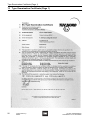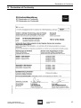
1
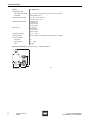
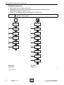
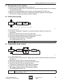
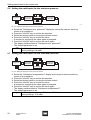
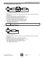
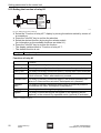
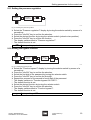
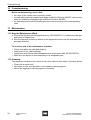
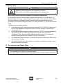
Operating Instructions
Control unit Ex p
> 8624/1
Contents
1
Contents
1
2
3
4
5
6
7
8
9
10
11
12
13
14
2
Contents ................................................................................................................2
General Information ...............................................................................................2
General Safety Information ...................................................................................3
Designated Use .....................................................................................................4
Technical Data ......................................................................................................5
Transport, Storage and Disposal ...........................................................................7
Assembly ...............................................................................................................7
Function/troubleshooting .....................................................................................11
Setting parameters for the control unit ................................................................17
Commissioning ....................................................................................................24
Maintenance ........................................................................................................24
Accessories and Spare Parts .............................................................................25
Type Examination Certificate (Page 1) ................................................................26
Declaration of Conformity ....................................................................................27
General Information
2.1 Manufacturer
R. STAHL Schaltgeräte GmbH
Am Bahnhof 30
D-74638 Waldenburg
Phone:
Fax:
Internet:
+49 7942 943-0
+49 7942 943-4333
www.stahl.de
2.2 Information regarding the Operating Instructions
ID NO.:
167921 / 862460300010
Publication Code:
S-BA-8624/1-01-en-30/07/2008
We reserve the right to make technical changes without notice.
2.3 Symbols Used
X
Z
X
)
Action request:
Describes actions to be provided by the user.
Reaction sign:
Describes the results or the reactions to the actions taken.
Bullet
Sentinel:
Describes the notes and recommendations.
Warning sign:
Danger from energised parts!
Warning sign:
Danger due to an explosive atmosphere!
2
Control unit Ex p
8624/1
167921 / 862460300010
S-BA-8624/1-01-en-30/07/2008
General Safety Information
3
General Safety Information
3.1 Safety Instructions for Assembly and Operating Personnel
The operating instructions contain basic safety instructions which are to be
observed during installation, operation and maintenance. Non-observance can lead to
endangerment of persons, plant and the environment.
WARNING
Risk due to unauthorised work being performed on the device!
Z Risk of injury and damage to equipment.
X Assembly, installation, commissioning, operation and maintenance must only be
performed by personnel who are both authorised and suitably trained for this purpose.
Before assembly/commissioning:
X Read through the operating instructions.
X Give adequate training to the assembly and operating personnel.
X Ensure that the contents of the operating instructions are fully understood by the
personnel in charge.
X The national installation and assembly regulations (e.g. IEC/EN 60079-14) apply.
When operating the device:
X Ensure the operating instructions are made available on location at all times.
X Observe safety instructions.
X Observe national safety and accident prevention regulations.
X Only run the device according to its performance data.
X Servicing/maintenance work or repairs which are not described in the operating
instructions must not be performed without prior agreement with the manufacturer.
X Any damage may render explosion protection null and void.
X No changes to the device impairing its explosion protection are permitted.
X Install and use the device only if it is undamaged, dry and clean.
If you have questions:
X Contact the manufacturer.
3.2 Warnings
Warnings are sub-divided in these operating instructions according to the following
scheme:
WARNING
Type and source of the danger!
Z Possible consequences.
X Measures for avoiding the danger.
They are always identified by the signalling word “WARNING“ and sometimes also have
a symbol which is specific to the danger involved.
167921 / 862460300010
S-BA-8624/1-01-en-30/07/2008
Control unit Ex p
8624/1
3
Designated Use
3.3 Conformity to Standards
The device complies with the following standards and regulations:
X Directive 94/9/EC
X EN 60079-0, EN 60079-2, EN 60079-7, EN 60079-11, EN 60079-18
4
Designated Use
The control unit 8624/1 is an explosion-protected device to monitor and control
overpressure in Ex p enclosures.
In combination with an appropriate enclosure with ingress protection ) IP54 (IP65
recommended) and the air supply unit, the control unit offers a pressurised protection.
In combination with the air supply unit, the control unit 8624/1 is approved for use in
hazardous areas zones 1 and 2 (category 2).
The control unit controls the overpressure in the Ex p enclosure and monitors the states
via the output contacts.
Pressurised enclosure
Two uses can be distinguished for pressurised enclosures:
X Operation with compensation of leakage losses
X Operation with permanent purging
)
In both operating modes, the enclosure should be minimum ingress
protection IP54 (IP65 recommended).
Operation with compensation of leakage losses:
In this operating mode, the potentially explosive gas mixture of the surrounding
atmosphere is first removed from the enclosure by purging. Then, an amount of
compressed air or inert gas high enough to compensate leakages in the enclosure and
to maintain a minimum overpressure with regard to the surrounding atmosphere is
supplied.
)
During the purging, a differential pressure of ) 4 mbar is built up.
During operation, a differential pressure of ) 2 mbar is sustained.
Operation with permanent purging:
In this operating mode, the enclosure is permanently flushed with compressed air or inert
gas for evacuating e.g. generated heat from the enclosure. The air outlet of the control
unit may be located in a potentially explosive atmosphere; it is certified correspondingly.
WARNING
Only use the device for its intended purpose!
Z Otherwise, the manufacturer’s liability and warranty expire.
X The device may only be used under the operating conditions described in these
operating instructions.
X The device may only be used in hazardous areas according to these operating
instructions.
4
Control unit Ex p
8624/1
167921 / 862460300010
S-BA-8624/1-01-en-30/07/2008
Technical Data
5
Technical Data
Version
Control Unit
Safety-specific data
Gas explosion protection
E II 2 G Ex mb e ia [px] [ia] IIC T4 or E II 2 G Ex mb e ia [px] IIC T4
Certificates
TÜV 07 ATEX 554304
Rated operational voltage
12 V / 24 V DC
24 V / 115 V AC ± 10%; 48 .. 62 Hz
230 V AC + 8.5 / - 10%; 48 .. 62 Hz
250 V AC + 5 / -15 %; 48 .. 62 Hz
Rated operational current
250 mA at 12 / 24 V DC
300 mA at 24 V AC
60 mA at 115 V AC
30 mA at 230 / 250 V AC
Ambient temperature
- 30 °C ( Tamb ( + 60 °C
Housing material
Epoxy resin, glass-fibre reinforced, black, antistatic
Switching threshold
of the output relay according to DIN VDE 0435:
Contact potential
Type of
current
max. current
value
Power factor cos p
250 V
AC
6A
1
240 V
AC
3A
0.3
24 V
DC
6A
30 V
DC
2.5 A
Service category
L/R
AC-15
0 ms
DC-13
50 ms
Terminals
Rated current
32 A for rated cross section and Ta ( 40 °C
Rated cross section
4 mm2 (12 AWG)
Terminal capacity
0.2 .. 4 mm2 (24 .. 12 AWG)
Dimensional drawings (all dimensions in mm) - subject to alterations
144.0
120.0
104.0
82.0
0.5
6.5
80.0
106.0
122.0
150.0
190.0
42.0
90.0
75.0
30.0
30.0
37.0
23.0
51.0
06078E00
Control unit 8624/1
167921 / 862460300010
S-BA-8624/1-01-en-30/07/2008
Control unit Ex p
8624/1
5
Technical Data
Version
Air Supply Unit
Safety-specific data
Gas explosion protection
E II 2 G Ex mb II T4/T5/T6 or E II 2 G Ex e mb II T4/T5/T6
Certificates
PTB 00 ATEX 2129 X
Rated operational voltage
12 V / 24 V 115 V / 230 V UC
230 V AC + 10% / - 10%
Rated operational current
600 mA at 12 V
300 mA at 24 V
60 mA at 115 V
30 mA at 230 V
Back-up fuse
1.0 A at 12 V
0.63 A at 24 V
0.125 A at 115 V
0.08 A at 230 V
Ambient temperature
-30 °C ... +60 °C
Housing material
Brass and epoxy resin, glass-fibre reinforced, black, antistatic
Pressure controller
Connection
1/4"
Outlet pressure
0.5 ... 3 bar
Flow
490 l/min
112 ... 135
180
Dimensional drawings (all dimensions in mm) - subject to alterations
64
63
06657E00
Air supply unit
6
Control unit Ex p
8624/1
167921 / 862460300010
S-BA-8624/1-01-en-30/07/2008
Transport, Storage and Disposal
6
Transport, Storage and Disposal
Transport
X Shock-free in its original carton, do not drop, handle carefully.
Storage
X Store in a dry place in its original packaging
Disposal
X Ensure environmentally friendly disposal of all components according to legal
regulations.
7
Assembly
)
Any mounting position is possible but make sure that the display is still legible.
7.1 Drilling of the assembly bore holes
.0
35
Ø
106.0
34.0
82.0
5
M
06357E00
Fig. 7-1: Drill pattern for control unit
Drill the following assembly holes on the housing wall:
X 4 threaded holes M5 (see Fig. 7-1)
X 1 hole d 35 mm for intake screw connection (see Fig. 7-1)
X 1 hole d 17 mm for air supply unit
167921 / 862460300010
S-BA-8624/1-01-en-30/07/2008
Control unit Ex p
8624/1
7
Assembly
7.2 Setting of the leakage air volume at the air supply unit
)
The leakage nozzle is set at factory to an air volume of 15 l/min,
at a pressure of 2 bar.
The pressure controller is set at factory to a pressure of 2 bar.
5
4.5
4
2 bar*
2.5 bar*
3.5
3
3 bar*
2.5
2
1.5
1
0.5
0
0
10
20
30
40
50
60
70
80
90
100
[l/min]
06079E00
* pressure set on pressure controller
Fig. 7-2: Leakage air diagram
06080E00
Fig. 7-3: Setting the leakage air volume
X Close the adjusting screw on the solenoid valve in clockwise direction as far as
possible.
X Turn the adjusting screw in anti-clockwise direction until the desired leakage air
volume is reached (see leakage air diagram, Fig. 7-2)
8
Control unit Ex p
8624/1
167921 / 862460300010
S-BA-8624/1-01-en-30/07/2008
Assembly
7.3 Assembly of the components
max. 5mm
1
11
2
3
10 9
5
4
8
6
7
06358E00
Fig. 7-4: Assembly of the components
X Put the O-ring 33.7 x 2.2 mm (3) between enclosure wall and control unit (4) and fix it
with the fixing screws (5).
X Screw the intake screw connection (1) together with the O-ring 33.7 x 3.5 mm (2) into
the control unit.
X Mount the solenoid valve (11) and the sealing disks (9,10) with the connecting piece
(8).
X Mount the pressure controller (7) on the connecting piece.
X Connect the pressure controller to the compressed air supply or the inert gas supply.
167921 / 862460300010
S-BA-8624/1-01-en-30/07/2008
Control unit Ex p
8624/1
9
Assembly
7.4 Connection of the components
Compressed air supply
)
The throughput of a preceding pressure controller or filter must be minimum
that of the digital controller.
07171E00
Fig. 7-5: Compressed air supply connection
X Connect the pressure controller to the compressed air supply (connection: G 1/4").
X Make sure that the volume flow required for operation is available (see table 7-1).
Supply pressure
(bar)
1.0
1.5
2.0
2.5
3.0
Minimum volume flow
Nozzle 2.0 mm Nozzle 2.5 mm
2.8 m3/h
4.6 m3/h
3.9 m3/h
6.25 m3/h
4.7 m3/h
7.5 m3/h
5.7 m3/h
9.5 m3/h
3
6.6 m /h
10.0 m3/h
Nozzle 3.0 mm
7.0 m3/h
9.0 m3/h
11.0 m3/h
13.5 m3/h
15.0 m3/h
Nozzle 3.8 mm
9.0 m3/h
15.0 m3/h
18.0 m3/h
22.0 m3/h
24.0 m3/h*)
Table 7-1: Minimum volume flow
Mains connection
K1
1
2 3
(+) (-)
4
5
6
7
programmable Ex-p-release
potential free
relay contact K1
9
8
2
10
1
valve
3
L1 (+)
N (-)
PE
07187E02
Fig. 7-6: Circuit diagram, standard version
X Carry out the connection of the control unit to mains supply and the connection
between control unit and solenoid valve in accordance with the circuit diagram
(see Fig. 7-6).
10
Control unit Ex p
8624/1
167921 / 862460300010
S-BA-8624/1-01-en-30/07/2008
Function/troubleshooting
K1
1
2 3
(+) (-)
4
6
5
7
9
8
Ex p-release
2
10
1
valve
3
external signal light
L1 (+)
N (-)
PE
07188E02
Fig. 7-7: Circuit diagram, connection of an external signal lamp
X
X
X
X
8
If necessary, connect a signal station to the potential-free contact K1 (see fig. 7-7).
Close the enclosure cover of the control unit carefully.
Carefully screw down all the cable entries.
Ensure that unused cable entries are sealed with plugs certified to Directive 94/9/EC.
Function/troubleshooting
8.1 General functional description
10,0
8,0
6,0
4,0
2,0
0,0
T1
T2
T3
07172E00
Fig. 8-1: General function
T1: After connecting the power and compressed air supply, the control unit starts a
self-test.
T2: Purging is finished.
The preset internal pressure of the enclosure is adjusted (2 mbar).
The devices in the Ex p enclosure are connected.
T3: Normal operation starts.
The internal pressure of the enclosure is regulated to the nominal value (2 mbar).
It is monitored in order not to fall below the MIN value (factory settings: 0.8 mbar)
or exceed the MAX value (factory settings: 15.0 mbar).
167921 / 862460300010
S-BA-8624/1-01-en-30/07/2008
Control unit Ex p
8624/1
11
Function/troubleshooting
8.2 Behaviour of the control unit in normal operation
In normal operation, the control unit controls and regulates the internal pressure of the
Ex p enclosure to the nominal overpressure compared to the surrounding atmosphere.
Factory settings are:
X MIN: 0.8 mbar
X MAX: 15.0 mbar
In case of increased internal pressure (factory settings: 4.0 mbar) compared to the
surrounding atmosphere, a mechanical valve of the control unit opens automatically. The
increased pressure is reduced until reaching the set value (factory settings: 3.5 mbar).
10,0
8,0
6,0
4,0
2,0
0,0
T1
T2
T3
T4
T5
07173E00
Fig. 8-2: Normal operation
T1: Purging is finished.
The preset internal pressure of the enclosure is adjusted (2 mbar).
The devices in the Ex p enclosure are connected.
T2: Normal operation starts.
The internal pressure is adjusted to the nominal value (2 mbar).
T3: The internal pressure of the enclosure increases.
T4: The internal pressure is reduced via the mechanical valve in the control unit.
T5: Normal operation starts.
12
Control unit Ex p
8624/1
167921 / 862460300010
S-BA-8624/1-01-en-30/07/2008
Function/troubleshooting
8.3 Behaviour of the control unit in case of fault
The system faults described in this chapter may only be eliminated by qualified
maintenance personnel.
Do not carry out any work on the control unit or digital controller before being authorized
so by the manufacturer.
Fault during purging
Purging is interrupted if:
X Power supply fails for more than 2 seconds
X The internal pressure of the enclosure falls below the set MIN value
(factory settings: 0.8 mbar)
X The internal pressure of the enclosure exceeds the set MAX value
(factory settings: 15.0 mbar)
X The volume flow (compressed air or inert gas) falls below the adjusted minimum flow
(factory settings: 0.6 l/s)
)
After having eliminated the fault, the control unit automatically starts a new
purging process.
20,0
18,0
16,0
14,0
12,0
10,0
8,0
6,0
4,0
2,0
0,0
T1
T3
T2
Fig. 8-3: Fault during purging
T1: Purging starts after connecting the power and compressed air supply.
T2: The internal pressure starts increasing.
T3: Purging is cancelled.
167921 / 862460300010
S-BA-8624/1-01-en-30/07/2008
Control unit Ex p
8624/1
13
Function/troubleshooting
Fault during normal operation
Normal operation is automatically deactivated if:
X Power supply fails for more than 2 seconds
X The internal pressure of the enclosure falls below the set MIN value
(factory settings: 0.8 mbar)
X The internal pressure of the enclosure exceeds the set MAX value
(factory settings: 15.0 mbar)
)
After having eliminated the fault, the control unit is activated automatically.
The control unit starts a new purging process if the pressure had fallen below
the MIN value.
20,0
18,0
16,0
14,0
12,0
10,0
8,0
6,0
4,0
2,0
0,0
T1
T2
T3
T4
T5
T6
T7
T8
Fig. 8-4: Fault during normal operation
T1: Purging is finished.
The preset internal pressure of the enclosure is adjusted (2 bar).
The devices in the Ex p enclosure are connected.
T2: Normal operation starts.
The internal pressure is adjusted to the nominal value (2 bar).
T3: The internal pressure starts falling.
The devices in the enclosure are switched off when reaching the MIN value.
T4: Repeated purging.
T5: Normal operation starts.
T6: The internal pressure starts increasing. The increased internal pressure cannot
escape via the mechanical valve of the control unit.
T7: The devices in the enclosure are switched off when reaching the MAX value.
T8: After pressure relief, normal operation starts again without repeated purging.
14
Control unit Ex p
8624/1
167921 / 862460300010
S-BA-8624/1-01-en-30/07/2008
Function/troubleshooting
8.4 Troubleshooting
Fault
number
01
02
03
04
05
06
07
08
09
Explanation
Elimination
Check sum error - Eprom defective
Remote control defective
Eprom error - Eprom defective. The values of the same
variables are different in all three Eproms
A/D converter DSS1 defective. Conversion not in value range
from 0 to 51.2 mbar.
A/D converter DSS2 defective. Conversion not in value range
from 0 to 51.2 mbar.
A/D converter DSS3 defective. Conversion not in value range
from 0 to 51.2 mbar.
Output relay fault. Output relay does not switch or does not
switch correctly.
Multiprocessor communication failed
A processor is defective
Inform the technical service of the manufacturer
Replace the remote control
Inform the technical service of the manufacturer
Table 8-1: Fault number according to self-test
Fault
Purging does not start
Purging is interrupted
Consequence
After connecting the operating
voltage, the remaining purging
time is not displayed
After connecting the operating
voltage and opening the
compressed air supply, the
remaining purging time is not
displayed
After 5 seconds, the remaining
purging time is reset to the initial
value
After more than 10 seconds, the
remaining purging time is reset
to the initial value
167921 / 862460300010
S-BA-8624/1-01-en-30/07/2008
Possible cause
Fuse in the control unit
defective
Elimination
Technical service by
manufacturer
Minimum overpressure for start Seal the enclosure and the
of purging is not reached
installed equipment, readjust
the leakage nozzle if necessary
Air quantity is not sufficient for Dynamic suction pressure too
successful purging
low (< "Switchpoint purging").
Set the suction pressure to
minimum 2 bar (dynamic
pressure)
Seal the enclosure and the
MIN pressure not reached.
installed equipment, readjust
Internal pressure of the
enclosures is not sufficient after the leakage nozzle if necessary
purging. Pressure decreases.
Air quantity is not sufficient for Increase the diameter of the air
supply tube
successful purging. Crosssection of the compressed air /
inert gas supply is too small
Pressure controller adjusted
Select 2.0 bar dynamic
incorrectly (e.g. 2 bar, static
pressure on the pressure
pressure)
controller (i.e. with throughput of
compressed air / inert gas)
Fuse of the flush valve is
Change the fuse on the digital
defective (valve is closed when proportional valve
de-energised)
Air quantity is not sufficient for Dynamic suction pressure too
successful purging
low. Set the suction pressure to
minimum 2 bar (dynamic
pressure)
Seal the enclosure and the
MIN pressure not reached.
installed equipment, readjust
Internal pressure of the
enclosures is not sufficient after the leakage nozzle if necessary
purging. Pressure decreases.
Air quantity is not sufficient for Increase the diameter of the air
supply tube
successful purging. Crosssection of the compressed air /
inert gas supply is too small
Pressure controller adjusted
Select 2.0 bar dynamic
incorrectly (e.g. 2 bar, static
pressure on the pressure
pressure)
controller (i.e. with throughput of
compressed air / inert gas)
Air quantity is not sufficient for Increase the diameter of the air
supply tube
successful purging. Crosssection of the compressed air /
inert gas supply is too small
Recalibrate to 1 bar suction
pressure. Double the purging
time
Control unit Ex p
8624/1
15
Function/troubleshooting
Fault
Consequence
Normal operation does not start The internal pressure is
after successful purging
displayed for approx. 4
seconds. Then the display is
switched off.
The internal pressure is
displayed during a short time
(longer than 4 seconds). Then
the display is switched off.
Possible cause
MIN pressure not reached.
Internal pressure of the
enclosures is not sufficient after
purging. Pressure decreases.
MIN pressure not reached.
Internal pressure of the
enclosures is not sufficient after
purging. Pressure decreases.
Pressure controller adjusted
incorrectly (e.g. 2 bar, static
pressure)
MAX pressure exceeded.
Internal pressure too high.
Pressure is increasing due to
e.g. heating
Elimination
Seal the enclosure and the
installed equipment, readjust
the leakage nozzle if necessary
Seal the enclosure and the
installed equipment, readjust
the leakage nozzle if necessary
Select 2.0 bar dynamic
pressure on the pressure
controller (i.e. with throughput of
compressed air / inert gas)
Readjust the leakage nozzle
Control the limit value for
"Switchpoint max. pressure"
and enter the new value.
Open or clean the air outlet of
the control unit
MAX pressure exceeded. Air
outlet (mechanical valve of the
control unit) is closed or clogged
Electrical wiring defective
Control electrical connections
Device switches off
permanently during running
operation
The internal pressure is
displayed but there is no
authorization for non-explosionprotected devices in the
enclosure
Device switches off
Internal pressure reaching limit
sporadically, then purging
value
restart
The suction pressure of the
system fails temporarily, e.g.
when switching on a large
consumer
Automatic disconnection of the Power supply fails more than 2
non-explosion-protected
seconds
devices in the enclosure
MIN pressure not reached.
Enclosure not tight
The display of the internal
pressure is not deactivated 4
seconds after pressure loss
(e.g. by opening the enclosure
door)
MIN pressure not reached.
Cross-section of the
compressed air / inert gas
supply is too small
MAX pressure exceeded. Air
outlet (mechanical valve of the
control unit) is closed or clogged
"Swichpoint min. pressure" set
incorrectly
Key-operated bypass switch is
active
Readjust the leakage nozzle
Increase the suction pressure
on the pressure controller to
max. 3.5 bar
Automatic restart
Seal the enclosure and the
installed equipment, readjust
the leakage nozzle if necessary
Replace the tubes by tubes with
larger cross-section
Open or clean the air outlet of
the control unit
Set a new limit value
Turn the key-operated switch to
the "Off" position
Table 8-2: Fault during operation
16
Control unit Ex p
8624/1
167921 / 862460300010
S-BA-8624/1-01-en-30/07/2008
Setting parameters for the control unit
9
Setting parameters for the control unit
WARNING
Danger from energised parts!
Z In order to set the parameters, the cover of the control unit must be
removed while the unit is energised.
X Open the cover only if guaranteed that there will not be any potentially
explosive atmosphere until closing the cover!
X Do not touch live parts!
9.1 Display and operating elements
Ex-p Control unit
BETRIEB
Gehäusedruck
0.80 mbar
1
OK
INFO
2
MENU
3
PE
L
in
N
K1
N
out
L
PE
Valve
07176E00
Fig. 9-1: Display and operating elements
Display /
Function
operating element
1 Display
Remaining purging time is displayed during purging.
Internal pressure is displayed during normal operation.
Error codes or fault messages are displayed in case of fault.
Saved parameters or parameters to be changed are displayed.
2 Selector switch
Selecting and changing parameters
3 Info/OK key
Loading and confirming parameters
9.2 Displaying / setting parameters
Displaying parameters
X Remove the cover of the control unit.
X Toggle between the different parameters by pressing the "Info/OK" key (for displayable
parameters see fig 9-2).
)
The control unit will return to the normal mode if the "Info/OK" key is not
pressed for 10 s.
167921 / 862460300010
S-BA-8624/1-01-en-30/07/2008
Control unit Ex p
8624/1
17
Setting parameters for the control unit
Setting the parameters
X Remove the cover of the control unit.
X Toggle between the different parameters by turning the selector switch
(adjustable parameters see fig. 9-2).
X Switch to the editing mode by pressing the "Info/OK" key.
)
The control unit will return to the normal mode if the selector switch is not
actuated for 10 seconds.
OK
INFO
MENU
Cabinet
pressure
- - . - - mbar
Language
?
OK
10 s
Purge
volume
- - - - ltr
10 s
Enter
purge volume
?
10 s
Switchpoint
min. pressure
?
10 s
Switchpoint
overpressure
?
10 s
min.
volume flow
?
10 s
Display
contrast
?
10 s
Function of
K1
?
10 s
Pressure
regulation
?
10 s
Function
bypass
?
OK
10 s
Function of
relay K1
--------OK
10 s
Switchpoint
min. pressure
- - . - - mbar
OK
10 s
Switchpoint
max. pressure
- - . - - mbar
OK
10 s
min.
volume flow
- - . - - l/sec
OK
displayable
parameters
adjustable
parameters
07177E02
Fig. 9-2: Parameters
18
Control unit Ex p
8624/1
167921 / 862460300010
S-BA-8624/1-01-en-30/07/2008
Setting parameters for the control unit
9.3 Resetting the factory settings
X Switch off the power supply of the control unit.
X Set the selector switch to the 1 o'clock position (arrow pointing upwards, then one step
in clockwise direction).
X Switch on the power supply of the control unit with pressed "Info/OK" key.
X Release the "Info/OK" key when "Load factory settings" appears on the display.
Z The control unit has been reset to factory settings.
9.4 Setting the language
Language
Language
OK
?
xxxxxxxxx
-English
-German
OK
07178E02
Fig. 9-3: Setting the language
X Select the "Language?" display by turning the selector switch by means of a
screwdriver.
X Press the "Info/OK" key to confirm the selection.
X Select the desired language by turning the selector switch.
X Press the "Info/OK" key to confirm the selection.
Z The display switches back to "Language?".
Z The desired parameter is set.
)
Factory settings: English
9.5 Adjusting the purge volume
OK
Enter
purge volume
?
OK
Enter
purge volume
xxxxx ltr.
+
50l/step
OK
confirm
purge volume
xxxxx ltr.
OK
5l/step
07179E02
Fig. 9-4: Adjusting the purge volume
X Select the "Enter purge volume?" display by turning the selector switch by means of a
screwdriver.
X Press the "Info/OK" key to confirm the selection.
X Select the desired value by turning the selector switch.
X Press the "Info/OK" key to confirm the value.
Z A request for confirming the value again is prompted.
X Press the "Info/OK" key to confirm the value again.
Z The display switches back to "Enter purge volume?".
Z The desired parameter is set.
)
Possible adjustment range: 5 l - 50.000 l
Factory settings: 100 l
167921 / 862460300010
S-BA-8624/1-01-en-30/07/2008
Control unit Ex p
8624/1
19
Setting parameters for the control unit
9.6 Setting the switchpoint for the minimum pressure
OK
switchpoint
min. pressure
?
OK
switchpoint
min. pressure
xxxxx mbar
+
1mbar/step
OK
confirm
min. pressure
xxxxx mbar
OK
0,05mbar/step
07180E02
Fig. 9-5: Setting the switchpoint for the minimum pressure
X Select the "Switchpoint min. pressure?" display by turning the selector switch by
means of a screwdriver.
X Press the "Info/OK" key to confirm the selection.
X Select the desired value by turning the selector switch.
X Press the "Info/OK" key to confirm the value.
Z A request for confirming the value again is prompted.
X Press the "Info/OK" key to confirm the value again.
Z The display switches back to "Switchpoint min. pressure?".
Z The desired parameter is set.
)
Possible adjustment range: 0.8 mbar - 25.0 mbar.
Factory settings: 0.8 mbar
9.7 Setting the switchpoint for the maximum pressure
OK
Switchpoint
overpressure
?
OK
Switchpoint
overpressure
xxxxx mbar
+
1mbar/step
OK
confirm
overpressure
xxxxx mbar
OK
0,05mbar/step
07181E02
Fig. 9-6: Setting the switchpoint for the maximum pressure
X Select the "Switchpoint overpressure?" display by turning the selector switch by
means of a screwdriver.
X Press the "Info/OK" key to confirm the selection.
X Select the desired value by turning the selector switch.
X Press the "Info/OK" key to confirm the value.
Z A request for confirming the value again is prompted.
X Press the "Info/OK" key to confirm the value again.
Z The display switches back to "Switchpoint overpressure?".
Z The desired parameter is set.
)
20
Possible adjustment range: 0.8 mbar - 25.0 mbar.
Factory settings: 15.0 mbar
Control unit Ex p
8624/1
167921 / 862460300010
S-BA-8624/1-01-en-30/07/2008
Setting parameters for the control unit
9.8 Setting the minimum volume flow
OK
min.
volume flow
?
OK
min.
volume flow
xxxxx l/sec
+
0.5 l/sec/step
OK
Confirm
volume flow
xxxxx l/sec
OK
0.1 l/sec/step
07182E02
Fig. 9-7: Setting the minimum volume flow
X Select the "min. volume flow?" display by turning the selector switch by means of a
screwdriver.
X Press the "Info/OK" key to confirm the selection.
X Select the desired value by turning the selector switch.
X Press the "Info/OK" key to confirm the value.
Z A request for confirming the value again is prompted.
X Press the "Info/OK" key to confirm the value again.
Z The display switches back to "min. volume flow?".
Z The desired parameter is set.
)
Possible adjustment range: 0.3 l/s - 3.6 l/s.
Factory settings: 0.3 l/s
9.9 Setting the display contrast
Display
contrast
?
OK
Display
contrast
[####_ _ _ _ ]
OK
07183E02
Fig. 9-8: Setting the display contrast
X Select the "Display contrast?" display by turning the selector switch by means of a
screwdriver.
X Press the "Info/OK" key to confirm the selection.
X Select the desired value by turning the selector switch.
X Press the "Info/OK" key to confirm the value.
Z The display switches back to "Display contrast?".
Z The desired parameter is set.
167921 / 862460300010
S-BA-8624/1-01-en-30/07/2008
Control unit Ex p
8624/1
21
Setting parameters for the control unit
9.10 Setting the function of relay K1
Function of
relay K1
?
OK
Function of
relay K1
xxxxxxxxx
.-Isolation
-System Fault
-Fault 1min
-Fault flash
-Prealarm MIN
-Prealarm MAX
-Purging
-Bypass
-Fault/Bypass
OK
07184E02
Fig. 9-9: Setting the function of relay K1
X Select the "Function of relay K1?" display by turning the selector switch by means of
a screwdriver.
X Press the "Info/OK" key to confirm the selection.
X Select the desired function by turning the selector switch
(for information on the available functions see table 9-1).
X Press the "Info/OK" key to confirm the function.
Z The display switches back to "Function of relay K1?".
Z The desired function is set.
)
Factory settings: Isolation
Functions of relay K1
Function
Isolation
The relay is normally closed and opens in case of a fault.
System Fault
The relay is normally closed and opens in case of a system fault.
Fault 1 min
The relay is normally closed and opens 1 minute after a fault occurred.
Fault flash
The relay is normally closed and opens for the first time 1 minute after
a fault occurred. Then it alternates every second.
Prealarm MIN The relay is normally closed and opens if the internal pressure has
fallen to 0.3 bar over the set value "Switchpoint min. pressure".
Prealarm
MAX
The relay is normally closed and opens when the internal pressure
exceeds the set value "Switchpoint overpressure".
Purging
The relay is closed during the purging.
Bypass
The relay is closed as long as the bypass in the operating device
(optional) or the external key-operated switch (optional) is activated.
Table 9-1: Functions of relay K1
22
Control unit Ex p
8624/1
167921 / 862460300010
S-BA-8624/1-01-en-30/07/2008
Setting parameters for the control unit
9.11 Setting the pressure regulation
Pressure
regulation
?
OK
Pressure
regulation
xxxxxxxxx
-pulsed
-Two-Position
OK
07185E02
Fig. 9-10: Setting the pressure regulation
X Select the "Pressure regulation?" display by turning the selector switch by means of a
screwdriver.
X Press the "Info/OK" key to confirm the selection.
X Select the desired function by turning the selector switch (pulsed or two-position).
X Press the "Info/OK" key to confirm the function.
Z The display switches back to "Pressure regulation?".
Z The desired function is set.
)
Factory settings: pulsed
9.12 Setting the bypass function
Function
bypass
?
OK
Enter
password
0000
OK
0-9
Function
bypass
ON
<OFF>
- ON
- OFF
OK
4x
07186E02
Fig. 9-11: Setting the bypass function
X Select the "Function bypass?" display by turning the selector switch by means of a
screwdriver.
X Press the "Info/OK" key to confirm the selection.
X Select the first digit of the password by turning the selector switch.
X Press the "Info/OK" key to confirm the first digit.
X Repeat this process for the second to fourth digit of the password.
Z The display switches to "Function bypass ON <OFF>".
Z The desired function is set.
X Select the desired function by turning the selector switch.
X Press the "Info/OK" key to confirm the selection.
Z The display switches back to "Function bypass?".
Z The desired function is set.
)
Factory settings: OFF
167921 / 862460300010
S-BA-8624/1-01-en-30/07/2008
Control unit Ex p
8624/1
23
Commissioning
10 Commissioning
Before commissioning, ensure that:
X the cover of the control unit is correctly closed,
X unused cable entries are sealed with plugs certified to Directive 94/9/EC, and unused
holes are sealed by stopping plugs certified to Directive 94/9/EC.
X the operating mode and the purging process is set according to the corresponding
zone.
11 Maintenance
11.1 Regular Maintenance Work
X Consult the relevant national regulations (e.g. IEC/EN 60079-17) to determine the type
and extent of inspections.
X Plan the intervals so that any defects in the equipment which may be anticipated are
promptly detected.
To check as part of the maintenance schedule:
X
X
X
X
Check that cables are clamped properly.
Inspect device for visible damage.
Compliance with the permitted temperatures in accordance with IEC/EN 60079-0.
Make sure the device is used according to its designated use.
11.2 Cleaning
The inspection window of the control unit must be cleaned only when it is heavily soiled.
X Clean with a moist cloth.
X Use water or mild, non-abrasive, non-scratching cleaning agents.
X Never use aggressive cleaning agents or solvents.
24
Control unit Ex p
8624/1
167921 / 862460300010
S-BA-8624/1-01-en-30/07/2008
Accessories and Spare Parts
11.3 Repair work
WARNING
Danger due to improper repair!
Z Improper repairs may impair the explosion protection!
X The control unit must be repaired only by the manufacturer!
Note in accordance with the ordinance on hazardous substances
In accordance with the German waste management act dated 27.8.1986 (AbfG. §11
Special waste) the owner of special waste is responsible for the disposal. At the same
time, the employer is obliged to protect his employees according to the German
ordinance on hazardous substances dated 1.10.1986 (GefStoffV. §17 General Protection
Duty).
Therefore, we must point out that:
1)
all the devices and/or systems which are sent back to R. STAHL for repair must
be free from hazardous substances (acids, caustics, solvents, explosive gas
compounds, etc.).
2)
all the devices and/or systems which are sent to R. STAHL must be handled in a
way that they do not contain any dangerous liquids or other hazardous
substances. Thus, devices and/or systems that have come into contact with
dangerous substances (see GefStoffV.) must be neutralised.
3)
the measures carried out under (1) and (2) during service and repair works must
be confirmed in writing.
4)
the costs that arise due to the disposal of hazardous substances during a repair
will be invoiced to the owner.
12 Accessories and Spare Parts
WARNING
Use of non-approved accessories and spare parts.
Z The manufacturer’s liability and warranty expire.
X Use only original accessories and original spare parts manufactured by R. STAHL.
167921 / 862460300010
S-BA-8624/1-01-en-30/07/2008
Control unit Ex p
8624/1
25
Type Examination Certificate (Page 1)
13 Type Examination Certificate (Page 1)
26
Control unit Ex p
8624/1
167921 / 862460300010
S-BA-8624/1-01-en-30/07/2008
Declaration of Conformity
14 Declaration of Conformity
167921 / 862460300010
S-BA-8624/1-01-en-30/07/2008
Control unit Ex p
8624/1
27
167921 / 862460300010
S-BA-8624/1-01-en-30/07/2008