1
GBM
INSTALLATION & OPERATING INSTRUCTIONS
990145 01/23/08
TABLE OF CONTENTS
SPECIFICATIONS....................................................................................... 1
MOUNTING................................................................................................. 3
WIRING ...................................................................................................... 4
THEORY OF OPERATION.......................................................................... 6
MILIVOLT INPUT OPTION JUMPER SELECTIONS................................... 7
FRONT PANEL OPERATIONS.................................................................... 8
PROGRAMMING FLOW CHART................................................................ 8
DEFINITIONS OF MENU PROMPTS.......................................................... 9
CALCULATING SCALE FACTORS............................................................. 11
PROGRAMMING......................................................................................... 12
TROUBLESHOOTING GUIDE.................................................................... 17
WARRANTY
DECODING PART NUMBER
SPECIFICATIONS
Features
• 5 Digit Scaling Factor
Stop / Reset:
Front Panel:
STOP/RST button stops batch if batch is running, Resets displayed value and relay outputs if batch is stopped.
Remote:
4-30 VDC, positive edge: stops batch if batch is running, Resets
batch amount if batch is stopped.
NOTE: Hold either front or remote reset active to inhibit any start
inputs.
Start:
Front Panel:
START button Starts batch by energizing Relay A (and Relay B if
Prewarn selected).
Remote:
4-30 VDC, positive edge: Starts batch by energizing Relay A (and
Relay B if Prewarn selected).
Scaling Factor (K-Factor): A user programmable K-Factor is used
to convert the input pulses to engineering units. The 5 digit K-Factor
divider, with decimal keyed into any position, allows easy direct entry
of any K-Factor from 0.0001 to 99999.
Presets: Two control outputs are provided. A 5 digit value can be
entered for both presets. The decimal point location is the same as
the counter (No decimal in Batch Total counter).
PRESET A:
The preset A output is dedicated to the batch amount. When
START is activated, Relay A will energize and remain on until
the batch is complete or the batch is stopped.
PRESET B:
The preset B output can be programmed to activate as a Prewarn
(for two stage batch control) or activate on Batch Total or Grand
Total (selectable).
When set for PREWARN, Relay B will energize when START is
activated and drop out at Prewarn number before preset.
When set for Batch Total or Grand Total, Relay B will activate
when the batch total or grand total counts up to preset B amount.
The output ON time can be set for a duration (0.01 to 99.99
sec.) or latched (0.00 setting). If a value other than 0.00 is set
for the duration, the batch total or grand total will auto-reset at
preset B.
Control Outputs:
Relays:
2 each N.O. Relays; 5 Amps 120/240 VAC or 28 VDC.
Lockout: Unauthorized front panel changes can be prevented by
entering a user selected 5 digit code. The front panel can be completely locked out (except Start & Stop/Reset) or the preset can
remain accessible.
Ratemeter: Accurate to 4 1/2 digits (±1 display digit). The rate display updates once per second. The rate meter can be programmed
to sample from 2 to 24 seconds maximum, and auto-range up to 5
digits of significant information. The ratemeter displays in units per
second, minute or hour.
Batch or Grand Totalizer: In addition to viewing the batch amount,
a second counter can be viewed. This counter is programmable to
count either the number of batches (Batch Total) or the grand total
count (Grand Total).
• Display Rate, Batch Size and
(Batch Total or Grand Total)
• Second B Relay Programmable for Output at
Prewarn or selected Batch/Grand Total
• Remote Start and Stop/Reset Inputs
• Pulse Input - 10 kHz Max.
• Security Lockout
• NEMA 4X / IP65 Front Panel
• 30mV Magnetic Pickup Input Option
Application:
The GBM miniature batcher is ideal for all batching applications. The
display will show Batch Amount, Rate and Batch/Grand Total at the
push of a button. The Start and Stop/Reset buttons make batching
simple.
Description:
The GBM is a 6 digit totalizer and 4.5 digit ratemeter with two relay
outputs. One output is dedicated to the batch amount (Preset A), the
other can be activated for Prewarn or Batch/Grand Total. The unit
can count up to the preset (reset to 0) or down from the preset (set
to preset). Start, Stop and Reset functions can be activated from the
front panel or remote inputs.
Specifications:
Display: 6 digit, 0.55” High LED
Input Power:
110 VAC ± 15% or 12 to 15 VDC
220 VAC ± 15% or 12 to 15 VDC
Current: 250 mA DC max. or 6.5 VA AC
Output Power: (AC powered units only)
+12 VDC @ 50 mA, unregulated -10 + 50%
Temperature:
Operating:
+32°F (0°C) to +130°F (+54°C)
Storage:
-40°F (-40°C) to +200°F (93°C)
Humidity: 0-90% Noncondensing
Memory: EEPROM stores data for 10 years if power is lost.
Inputs:
High Impedance DC pulse input 4-30 VDC (high), Open or 0-1
VDC (low), 10 K ohm impedance, 10 kHz max. speed.
-M Option:
Mag. Input, Input A accepts 30mV input (50 V max. P/P) signals 10 K ohm impedance, 5 kHz max.
1
SPECIFICATIONS
(continued)
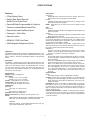
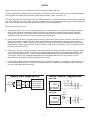
Dimensions:
3.925
(99.7)
4.245
(107.8)
0.587
(14.91)
4.437
(112.7)
3.622
(92)
Panel
Cutout
2.625
(66.68)
CUSTOMER PANEL
Panel Thickness 0.062" (1.5)
to 0.187" (4.7) max.
BEZEL
GASKET
Application
STOP
RST
A
B
C
D
E
ENTER
LOCK
PRE A
PROG
VIEW
START
Flowmeter
Solenoid Valve
2
1.772
(45)
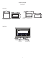
MOUNTING
The unit is designed to be mounted with a gasket providing a water tight seal. Two mounting brackets are provided to secure
the unit to the panel. A panel less than .1" may distort if the clamps are screwed too tightly.
Slide the body of the unit through the rubber gasket. Insert the unit into the panel. As shown in "FIG. A", slide the brackets
up the groove to press against the back of the panel. Insert screws into rear of brackets and tighten them evenly and alternately. Do not over tighten! A normal level of torque is required. Maximum torque should be 3" pounds.
This product is designed to be panel mounted and is NEMA 4 rated if proper mounting procedures are followed and the
required and supplied hardware is correctly used.
If the panel in which the unit is mounted is less than .125 of an inch thick, the possibility exists that there will be some flexing. Should this flexing occur, the resulting deformation of the panel could cause a loss of the water tight seal. In case this
should occur, the use of silicone or other sealant would be recommended.
This product is designed to the NEMA 4 standard. However, the fact that we are unable to control either the location in which
the device is installed or the actual installation itself requires that the company's liability shall extend only to the repair or
replacement of a defective product.
We are prepared to offer additional assistance in those special situations where normal mounting methods do not seem
to satisfy the customers needs. This assistance may be obtained by calling the factory and asking for Industrial Customer
Service.
FIG. A
FIG. A
DIMENSIONS
3.925
(99.7)
0.587
(14.91)
4.437
(112.7)
4.245
(107.8)
3.622
(92)
Panel
Cutout
2.625
(66.68)
BEZEL
GASKET
3
CUSTOMER PANEL
Panel Thickness 0.062" (1.5)
to 0.187" (4.7) max.
1.772
(45)
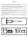
WIRING
The rear terminal contains 12 screw terminals for connecting #14 to #28 gauge wire.
The unit is controlled by a microprocessor and, therefore, an electrically "noisy" environment could cause operating problems.
The input power line should not be common to power lines for motors, pumps, contactors, etc.
The unit is designed to be immune from line or RF voltage interference. In some environments voltage spikes of over 100
volts, even 1000 volts, can occur. When common to a power line driving motors voltage fluctuations can be extreme and
rapid. Lines driving DC or AC solenoids, relays, or actuators can also cause problems.
Four sources of noise can occur:
1)
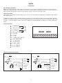
AC power line noise - If the unit cannot be connected to a clean power source, an inductive load suppressing device
(MOV as GE # V130LA1 or Resistor Capacitor as Paktron # .2 uf/220 ohm @ 400V) can be installed. Although
locating the suppressor across the AC supply at the unit should help, best results are obtained by connecting the
suppressor across the leads of the "load" at the device causing the spike.
2)
Input line noise -The noise is carried on the input and D.C. ground lines. Make sure the input wires are never run into
the unit in a bundle with power input lines. Also, keep these input lines isolated from inductive lines from devices
drawing heavy loads. If there is a possibility of electrical noise, we recommend using shielded cable, with the shield
being hooked to the D.C. ground terminal on the instrument, and to "earth" at one point in the circuit, preferably at the
D.C. ground terminal of the unit.
3)
Output lines - The unit has two relay outputs. When these outputs are used to run external relays or solenoids, spikes
can be generated upon activation. This noise can spread through the instrument causing operating problems. If the
source is a D.C. operated device, a general purpose diode (IN4004) placed across the solenoid prevents electrical
noise spikes. Connect the cathode (banded side) to the more positive side of the coil. If the source is an A.C.
operated device, use a MOV or Resistor Capacitor across the coil.
4) 12 VDC output supply - Noise can be generated on the 12 VDC output supply if it is used to drive inductive loads or if
the current draw exceeds 50 mA. Insure that all inductive loads have a diode (such as IN4004) across the coil and
that the current does not exceed 50 mA.
Relay Contact Suppression
Supply Line Suppression
DC Load
AC
SUPPLY
OPT.
RFI
LINE
FILTER
MOV
CAP
+
SUPPRESSION
AT AC INPUT
RELAY
CONTACT
ELECTRONIC
INSTRUMENT
DC
SUPPLY
DIODE
ELECTRONIC
INSTRUMENT
AC Load
AC
SUPPLY
RELAY
CONTACT
ELECTRONIC
INSTRUMENT
4
LOAD
CAP
LOAD
MOV
WIRING
(continued)
AC / DC Power Connections
NOTE: Connect power only after other connections are finished. Do not touch the live AC power terminals! The unit has been designed with an isolated AC input. Thus, polarity is not a concern for the AC input. Connect AC power to pins 11 and 12. The chassis is
plastic, therefore earth ground is not used. For D.C. operation, connect + 12V to pin 7 and - D.C. to pin 8.
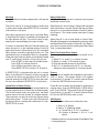
Sensor Connections
These diagrams show how to hook typical input sensors to the unit. The unit supplies an unregulated 12 Volt (50mA) output to power
these sensors (Pin 7).
A valid pulse is one which makes a transition from the off-state (0 to 1V) to the on-state (4 to 30V): a positive going edge. The input
impedance is 10K Ohms to ground. The unit can be programmed from the front panel for slow switch closure inputs up to 40Hz (select
"Lo CPS"), or solid state switches (select "hi CPS") up to 9.99KHz. No rear terminal jumpers are required. Use PNP (sourcing) type
pulsers.
Wiring Terminations:
RELAYS
A
1- COMMON
2- N.O.(N.C./NPN)
3- COMMON
4- N.O.(N.C./NPN)
5- COUNT
6- START
7- 12VDC OUT/+DC IN
8- -DC (GROUND)
9- STOP/RESET
10- NOT USED
11- A.C. INPUT
12- A.C. INPUT
B
REAR VIEW
1
2
3
4
5
6
7
8
9 10 11 12
Typical Flowmeter Connections
High Impedance (4-30VDC) Pulse Input with Analog Output
Magnetic Pickup (30 mV) Pulse Input
115 VAC
115 VAC
MOV
recommended
MOV
recommended
A
Turbine Flowmeter
(preamplifier fitted)
AC
Power
+
–
Low level mV pulse
–
Turbine Flowmeter
(without preamplifier)
5
AC
Power
High level voltage pulse
B
115 VAC
SOLENOID
VALVE
B
115 VAC
SOLENOID
VALVE
1- COMMON
2- N.O.(N.C./NPN)
3- COMMON
4- N.O.(N.C./NPN)
5- COUNT
6- START
7- +12VDC OUT/+DC IN
8- -DC (GROUND)
9- STOP/RESET
10- NOT USED
11- A.C. INPUT
12- A.C. INPUT
RELAYS
A
RELAYS
1- COMMON
2- N.O.(N.C./NPN)
3- COMMON
4- N.O.(N.C./NPN)
5- COUNT
6- START
7- +12VDC OUT/+DC IN
8- -DC (GROUND)
9- STOP/RESET
10- NOT USED
11- A.C. INPUT
12- A.C. INPUT
THEORY OF OPERATION
Batching
After the batcher has been programmed, it will operate
as follows:
Relay B Operation
Relay B can be programmed as a prewarn relay or grand
total/batch counter alarm.
The unit will reset to "0" (count up mode) or load Preset
A (count down mode) when RESET/STOP is activated.
(front button or rear input)
When Relay B is set for Prewarn, Relay B will energized
when the batcher is started. Relay B will drop out when
the count is at the selected number (Preset B) before
final Preset A. This is often used for slow down (2 stage
batching).
When Start (front button or rear input) is activated, Relay
A (and Relay B if Prewarn is selected) will energize and
the right decimal will light. The unit will count in engineering units corresponding to the input scaling.
When Relay B is set for total (Batch or Grand Total),
Relay B will energize for the selected time duration when
the Batch/Grand Total reaches Preset B. If the Relay is
set to latch, it can be reset by resetting the Batch/Grand
Total. (as described above).
If Prewarn is selected for Relay B, Relay B will drop out
when the count is at the selected number (Preset B)
before final Preset A. When Preset A (or "0") is reached,
Relay A drops out and the right decimal turns off. (The
right decimal turns on whenever Relay A is energized).
At the end of the batch the display is immediately loaded
with "P" and Preset A number. At this point you can:
Press START to reset and start another batch
Press PRE A to change Preset A
Press VIEW to view count (over-run)
Press RESET/STOP to reset to "0" (Preset A)
Relay B as Scaled Pulse Output
To use output B as a scaled output proceed as follows:
1) Select gr tot under count section of menu.
2) Select tot under relay section of menu.
3) Enter the desired duration for the B Relay.
4) Set Pre B at desired scaling (pre b is a divider).
Maximum output frequency is 15 pulses/second.
If RESET/STOP is activated while the unit is started,
Relay A (and Relay B if Prewarn) will drop out and the
last count will remain on the display. Press START to
continue the batch or RESET/STOP to abort the batch.
All starts are inhibited if RESET/STOP is held active.
Presets
Preset A can be viewed and changed by pressing the
"PRE A" button. The present Preset A will appear.
Press buttons "A" through "E" to load in desired Preset
A. Press the ENTER button once to enter.
Grand Total or Batch Counter
The second counter (displayed with inverted decimals)
can be programmed as a Grand Total or Batch counter.
The Grand counter counts the grand total, the Batch
counter counts the total number of complete batches.
These counters can only be reset from the front panel
while viewing them. To reset, press the VIEW key until
the displays shows a number with all decimals lit. Press
RESET/STOP to reset.
Preset B can be viewed and changed by entering the
program menu. Press the PRGM button. PRE B will appear. Press ENTER. The present Preset B will appear.
Press buttons "A" through "E" to load in desired Preset
B. Press the ENTER button once to enter.
VIEW Button
The VIEW button allows you to alternately view:
1. Count of "A" (Batch)
2. Rate of "A" (Batching speed)
3.* A) Grand Total if "gr tot" is selected
B) Number of Batches if "BA tot" is selected
*All decimal points are inverted when Grand/Batch Total
is being displayed.
6
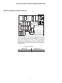
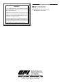
Millivolt Input Option JUMPER SELECTIONS
Millivolt Input Option Jumper Selections
J3
C7
U2
C5
U4
U1
J6
J5
CR2
C3
R1
R2
C4
C9
R3
CR4
CR5
J4
C1
J1
J2
C2
P1 REV B
R10 C6
R6
CR1
CR6
R9
R8
U5
U3
CR3
U6
R4 R5 R7 C8
20229
If the unit has the millivolt input bd.# 20229, the count input
can be separately solder jumper programmed to accept
either a low millivolt or 4-30 V input. Each unit shipped is
programmed according to part number. If solder jumpers
are made, the part number should be modified to reflect the
changes made
C=CLOSE, O=OPEN
4-30V INPUT
J1-O, J2-C, J3-O
Millivolt INPUT
J1-C, J2-O, J3-C
7
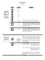
FRONT PANEL OPERATIONS
STOP
RST
D
C
B
A
ENTER LOCK PRE A PROG
Press to STOP /
RESET in operating
mode; Press to "ENTER" in programming mode.
Press to "enter"
LOCK code for
panel lock.
Press to view or
change Preset A
E
VIEW START
Press to cycle
through PROGRAM choices;
Press to step
through set up
choices in program mode.
Press to alternately view Rate,
A Total or B Total
Press to Start
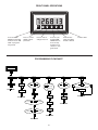
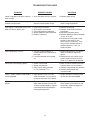
PROGRAMMING FLOWCHART
Start Here
PRGM
pre b
FACToR
PRGM
ENTER
#####
ENTER
RUN MODE
CouNT
PRGM
ENTER
DP FAc
RATE
PRGM
PRGM
SET
PR
ENTER
#####
PRGM
SECS�
NNiNS�
hours
ENTER
RUN MODE
ENTER
ENTER
LC�
PRg
PRGM
LC�
ALL
ENTER
DP LoC
ENTER
RELAY
PRGM
ENTER
ENTER
RST�
0
LoC
PRGM
ENTER
NoR ##
ENTER
CoDE
#####
ENTER
gr tot
ba tot
PRGM
ENTER
ENTER
hi cps
ENTER
FiguR#
lo cps
DLY #
PRGM
ENTER
ENTER
RUN MODE
RUN MODE
8
RUN MODE
tot
ENTER
preuu
PRGM
##.##
ENTER
RUN MODE
ENTER
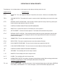
DEFINITIONS OF MENU PROMPTS
The following is a list of abbreviations as they appear on the display and front panel of the unit.
ABBREVIATION
DESCRIPTION
PRE B
PRESET B - This is the setpoint for Relay B. Preset B can be used as a Prewarn or Grand/Batch Total
alarm.
FACTOR
SCALING FACTOR - This portion of the menu is used to set the 5 digit dividing scale factor for the count
input.
DP F A
DECIMAL POINT FOR FACTOR A - Enter location of decimal point for scaling Factor A by pressing the
button under the digit where the decimal is desired.
COUNT
PORTION OF MENU FOR SETTING COUNTER VARIABLES
RST 0
RESET TO 0 - Counter will reset to 0. The Batcher will count up from 0.
SET PR
SET TO PRESET - Counter will reset to preset A. The Batcher will count down from preset A.
DP LOC
DECIMAL POINT LOCATION - Enter desired location of decimal by pushing the button under the digit
where the decimal is desired. Changing the decimal will change the decimal location in the counter's
presets and rate display.
gr tot
GRAND TOTAL- This sets the second counter to count the Grand Total.
ba tot
BATCH TOTAL- This sets the second counter to count the number of Batches.
HI CPS
HIGH COUNTS PER SECOND - This sets the unit for high count speeds (0-9.99 kHz)
LO CPS
LOW COUNTS PER SECOND – This sets the unit for contact debounce filtering (0-40 Hz)
RATE
PORTION OF MENU FOR SETTING RATE VARIABLES
sec
SECONDS - The rate display will read in rate per second.
mins
MINUTES- The rate display will read in rate per minute.
hours
HOURS - The rate display will read in rate per hour.
NOR##
FIGUR ##
NORMALIZING FACTOR - Normalizes (averages) the data being received. Higher settings provide more
normalizing (averaging) for a more stable display. Derived from the equation:
(Old Data x "NOR" + New Data)
("NOR" + 1)
SIGNIFICANT FIGURE - This sets the amount (1-5) of meaningful figures the unit will display. (RATE DIS
PLAY ONLY). FOR EXAMPLE: If "2" is set as the figure, a rate of 273.45 will be displayed as 270.
9
DEFINITIONS OF MENU PROMPTS
(continued)
ABBREVIATION
DESCRIPTION
DLY##
DELAY FACTOR - The amount of time (02 to 24 sec.) the unit will "look" for valid data, before the display
defaults to zero. (RATE DISPLAY ONLY)
LOC
LOCK - This portion of the menu allows you to set lock functions (Lock functions apply only to front panel)
1) lock the program (Preset A is still accessible)
2) lock all (locks program & presets; Start & Stop/Reset are accessible).
LC PRG
LOCK PROGRAM - This will lock the program. Preset A can be changed, start, stop & reset will function
when the unit is in the lock mode (lock ON).
LC ALL
LOCK ALL - This will lock the program and the presets when the unit is in the locked mode. Preset A can
be viewed, but not changed. Start and Stop/Reset buttons will still operate.
CODE
LOCK CODE - This message (code) will flash on display for approximately 3 seconds. It will be followed
by a 5 digit number (xxxxx). The number you enter here will be the code to lock and unlock the unit.
RELAY
RELAY - This portion of the menu allows you to set your relay operation variables.
preuu
PREWARN - When this is selected Relay B energizes when started and drops out at "Preset B" amount
before batch is complete.
TOT
RELAY B FOR TOTALIZER - When this is selected relay B will activate when the selected Grand or Batch
total has reached Preset B.
b##.##
RELAY B DURATION - This message will appear when "TOT" is selected. It is the duration which the
relay will remain energized (00.01 to 99.99 sec). If 00.00 is selected, the relay will latch until reset. When
the duration is not at 00.00, the Grand/Batch totalizer will autorecycle.
10
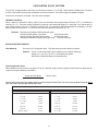
CALCULATING SCALE FACTORS
The unit has a programmable scale factor to scale the input pulses. It is a 5 digit , floating decimal divider factor. The factor
to enter is the number of pulses per the desired unit of measurement. The factor ranges from 0.0001 to 99999.
Scale factor calculations are simple. Here are some examples:
DECIMAL LOCATION:
When a decimal is desired for display, special care must be taken when programming the Factor (factor) and Decimal
Location (Dp loc). The factor must be entered in pulses per units desired for display. (i.e. pulse per 1 unit, pulses per 0.1
units, pulses per 0.01 units, etc.) The Decimal Location (Dp loc) controls the decimal placement for the display. For each
decimal place you move for Dp loc, you must also move the decimal for the factor (dp f a).
Example:
The flow sensor outputs 678.4 pulses per gallon.
To display whole gallons (1 gal) enter 678.4 for the factor
To display tenths of gallons (0.1 gal) enter 67.84 for the factor
To display hundredths of gallons (0.01) gal) enter 6.784 for the factor
SCALING FACTOR EXAMPLES:
Flow Batching:
You want to fill a 55.0 gallon drum. The flow sensor gives 387 pulses per gallon.
Solution - Dial in a scale factor of 38.7 (38.7 to display 0.1 gal; 387 for whole gal.)
Under count, set dploc to dplo.c to read tenths of gallons.
Set PRE A at 55.0; Wire Relay A to solenoid valve.
Converting Scale Factors
When different units of measure are given than what is desired, simply convert the given Scale Factors to reflect the desired units using the following calculations.
Pulses Per Unit (given)
Units Conversion Factor
= Scale Factor
Use the Units Conversion Chart below when converting the given Scale Factor. Be sure to use the Scale Factor for whole
units and divide it by the proper Conversion Factor.
UNITS CONVERSION CHART
To convert: ft to m
ft2 to m2 ft3 to m3 ft3 to gal gal to l gal to m3 gal to ft3 gal to lb (H2O)
divide factor by
0.3048
0.0929
0.02832
7.4805
3.7854
0.00379
0.1337
8.3378
To convert:
kg to lb
l to ft3
l to gal
m to ft
2
2
m to ft m3 to ft3 m3 to gal
lb to kg 11
divide factor by
2.2046
0.0353
0.2642
3.2808
10.7639
35.3147
264.172
0.45359
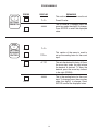
PROGRAMMING
STEP
1
SETTING
PRESET B
PRESS
PRGM
DISPLAY
REMARKS
This section of the menu is used to set
Preset B value.
pre b
This is Preset B. To change, press the
arrow key under the digit(s) to change.
Press ENTER to enter the displayed
value.
#####
ENTER
STEP
2
SETTING
SCALING
FACTOR
PRGM
PRGM
pre b
This section of the menu is used to
set up the scaling factor for the count
input.
Factor
dp fac
This sets the decimal for factor A. Press
the arrow key under the digit where
the decimal is desired. To clear the
decimal, press the arrow key furthest
to the right (PRGM) .
#####
This is the scaling factor for the count
input. To change, press the arrow key
under the digit(s) to change. Press
ENTER to enter the displayed value.
ENTER
ENTER
12
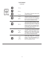
PROGRAMMING
(continued)
PRGM
STEP
3
SETTING
THE
COUNTER
PRGM
PRGM
ENTER
ENTER
ENTER
ENTER
pre B
factor
This section of the menu sets up the
counter information.
count
rst 0
or
set pr
Press the PRGM key to choose RST 0
(reset to 0, count up) or SET PR (set to
preset, count down), press the ENTER
key to enter the displayed choice.
dp loc
This sets the decimal location for the A
& B counters. Press the arrow key under
the desired digit location. To clear the
decimal, press the arrow key furthest
to the right. Press the ENTER key to
enter the displayed location.
gr tot
or
ba tot
This section sets the second counter
operation. Press the program key to
choose GR TOT (Grand Total) or BA
TOT (Batch Total). Press the ENTER
key to enter the displayed choice.
Press the PRGM key to choose
HIGH CPS (0-9.99KHz) or LOW CPS
(0-40Hz). Press the ENTER key to
enter the displayed choice.
hi cps
or
lo cps
13
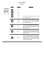
PROGRAMMING
(continued)
PRESS
STEP
4
SETTING
THE RATE
PRGM
PRGM
PRGM
PRGM
ENTER
DISPLAY
REMARKS
pre b
factor
count
rate
This section of the menu is used to set up
the rate information.
secs
mins
or
hours
Press the PRGM key to choose secs (rate
per second), mins (rate per minute)or
hours (rate per hour). Press ENTER to
enter displayed choice.
This sets the normalizing (averaging) factor. Press the arrow keys under the desired
digits to change. Press ENTER to enter
displayed value.
nor ##
ENTER
This sets the number of significant figures
to be displayed. Press the arrow key under
the digit to change. Press ENTER to enter
displayed value.
figur #
ENTER
This sets the delay time (2 to 24 sec.) that
the unit will "look" for valid input data before
the display falls to 0. Press the arrow key
under the digits to change. Press ENTER
to enter displayed value.
dly #.#
ENTER
14
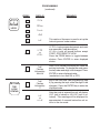
PROGRAMMING
(continued)
PRESS
STEP
5
SETTING
LOCK
DISPLAY
REMARKS
pre b
PRGM
factor
PRGM
count
PRGM
rate
PRGM
loc
PRGM
ENTER
ENTER
SETTING
THE
LOCK
STATUS
LOCK
ENTER
LC PG
or
LC ALL
This section of the menu is used to set up the
lockout type and code number.
LC PG = Locks program but presets and reset
are accessible. (see description)
LC ALL= Locks all keypad buttons except
START, STOP/RESET & VIEW.
Press the PRGM button to toggle between
choices; Press ENTER to enter displayed
choice.
CoDE
Flashes
followed by:
#####
After CODE flashes the display will show the
existing lock code. To change the code press
the key under each digit to be changed. Press
ENTER to enter displayed value.
(see below to turn lock ON or OFF)
CoDE
Flashes
followed by:
0
Key in the lock code (see programming step
4) by pressing the keys under the digits to be
changed. Press the ENTER key to enter the
displayed code.
LoC
or
uN LoC
After the code is entered the unit will display
LOC (unit is locked) or UN LOC (unit is unlocked). This message will be displayed for
approximately 3 seconds before the unit returns to the run mode.
15
PROGRAMMING
(continued)
PRESS
PRGM
STEP
6
SETTING
THE
RELAYS
PRGM
PRGM
PRGM
PRGM
PRGM
ENTER
DISPLAY
pre b
factor
count
rate
loc
relay
This section sets up the relay information.
tot
or
preuu
Press the PRGM key to choose tot (Relay B
assigned to total) or PREW (Relay B assigned
to prewarn). Press enter when the desired
choice is displayed.
b##.##
This will only appear if tot selected. This is
the duration (.01 to 99.99 sec) that relay B
will remain energized. If 00.00 is selected, the
relay will latch until reset.
ENTER
SETTING
THE
PRESETS
PRE A
PRGM
REMARKS
PRE A
Followed by
last PRE A
entered
PRE B
PRE A = Preset A (Batch Amount); The set
point at which output A will drop out after
started. If the displayed value is not the desired preset, press the keyunder the digit(s)
to be changed.
PRE B = Preset B ;
a) Tot selected
The set point at which
output B will energize.
b) preuu selected The number of counts
before batch ends that
output B will drop out.
If the displayed value is not the desired
preset, press the key under the digit(s) to be
changed.
16
TROUBLESHOOTING GUIDE
PROBLEM
POSSIBLE CAUSES
SOLUTIONS
Power is applied to unit but the display 1. AC or DC power wiring is incorrect.
does not light.
1.Recheck power wiring
Unit works, but occasionally the display 1. Line noise is affecting the processor
freezes or skips counts.
due to a current spike or surge.
1.Use a different power supply or
install a surge suppressor.
Input signal is connected but the unit 1. Input wiring is incorrect.
does not count or display rate.
2. Scale factors are incorrect.
3. Transmitting device is defective.
4. Wrong debounce filtering selected.
5. Batcher is defective.
1.Recheck input wiring.
2.Recheck scale factors and factor
calculations.
3.Replace transmitting device.
4.Recheck debounce filtering selection
"hi cps" or "lo cps".
5.To confirm set scale factor at one,
connect a wire to pin #7 and
touch it to pin # 5 (input A). Each
time pin #5 is touched counter A
should count once. If not, call
factory for RMA.
Rate is displaying: r FFFFF.
1. The unit is trying to display a
number which it can't (too small or
too large).
2. Line noise affected unit on power
up.
1.Check scaling factor, if it is correct,
lower the number of significant
figures.
2.Reprogram the unit and be sure to
enter a decimal (enter one and re
move it if a decimal is not desired).
Relays are not activating properly.
1. START not activated.
2. Wrong relay duration.
3. Relay set for wrong activation
i.e. tot instead of preuu.
1.Relay A (and B if Prewarn) will only
energize when start is activated.
2.Recheck programmed relay duration.
3.Recheck programmed relay
activation mode.
Grand / Batch Counter resets before 1. Relay duration is set at a value
reaching 999999.
other than 00.00. This causes the
counter to auto-reset at the preset.
1.If Relay B output is not being used,
set the relay duration to 00.00.
Various menu items are not being dis- 1. The menu flow chart and the setup
played.
steps show the setup for units with
all of the available options. Options
not ordered will be suppressed in
the programming menu.
1.Disregard any menu items
which appear on the flowchart and
setup steps, but do not appear on
the unit's display.
17
Ordering Information
WARRANTY
GBM 110 = 110 VAC Powered
GBM 220 = 220 VAC Powered
This product is warranted against defects in materials
and workmanship for a period of one (1) year from the
date of shipment to Buyer.
OPTIONS: (add to end of Part number)
-M = Magnetic Pickup Input
The Warranty is limited to repair or replacement of the
defective unit at the option of the manufacturer. This
warranty is void if the product has been altered, misused,
dismantled, or otherwise abused.
ALLOTHER WARRANTIES, EXPRESSED OR IMPLIED,
ARE EXCLUDED, INCLUDING BUT NOT LIMITED TO
THE IMPLIED WARRANTIES OF MERCHANTABILITY
AND FITNESS FOR A PARTICULAR PURPOSE.
18