1
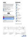
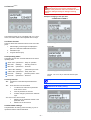
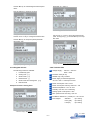
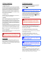
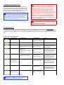
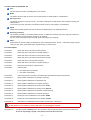
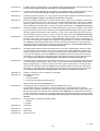
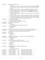
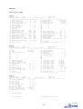
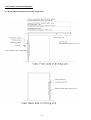
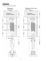
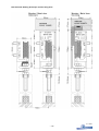
Operating Manual Sliding Door Drive Engine V1.10EN 2609 Table of Contents 1.0 General_______________________________________________________________________3 1.1 Information......................................................................................................................................................................3 1.2 Safety and Information Symbols...................................................................................................................................3 1.3 Instruction ......................................................................................................................................................................3 2.0 Product Versions_______________________________________________________________3 2.1 Model...............................................................................................................................................................................3 2.2 Motor................................................................................................................................................................................3 2.3 Opening Direction...........................................................................................................................................................3 2.4 Form.................................................................................................................................................................................3 2.5 Type..................................................................................................................................................................................3 2.6 Design..............................................................................................................................................................................3 2.7 Assembly.........................................................................................................................................................................3 2.8 Example (wall-mounting)...............................................................................................................................................3 2.9 Terminal (optional).........................................................................................................................................................4 2.9.1 2.9.2 2.9.3 2.9.4 Basic function...................................................................................................................................................................................4 Operating states................................................................................................................................................................................4 Key function.......................................................................................................................................................................................4 Parameter settings............................................................................................................................................................................4 3.0 Range of application____________________________________________________________6 3.1 Application Area.............................................................................................................................................................6 3.2 Improper use...................................................................................................................................................................6 3.3 Safety...............................................................................................................................................................................6 4.0 Assembly_____________________________________________________________________6 5.0 Putting into operation___________________________________________________________6 5.1 Precondition....................................................................................................................................................................6 5.2 Set-up procedure............................................................................................................................................................6 5.2.1 with terminal (plug-in terminal 50-53).............................................................................................................................................6 5.2.2 with notebook (plug-in terminal 1-3)...............................................................................................................................................6 5.3 Fault clearance during putting into operation procedure..........................................................................................6 6.0 Features______________________________________________________________________7 6.1 Standard feature.............................................................................................................................................................7 6.2 Optional Features ..........................................................................................................................................................7 6.3 Safety features................................................................................................................................................................7 7.0 Maintenance / Safety check______________________________________________________8 8.1 Error code / Trouble Shooting.......................................................................................................................................8 9.0 Parameters____________________________________________________________________9 9.1 Parameter list Terminal / RS232....................................................................................................................................9 9.2 Terms used on parameter list.....................................................................................................................................10 9.2.1 Description.......................................................................................................................................................................................10 10.0 Setup by RS232 (PC, notebook)_________________________________________________14 10.1 Configuration..............................................................................................................................................................14 10.2 List...............................................................................................................................................................................15 11.0 Terminal connection diagrams__________________________________________________16 11.1 Wiring diagram (maximum total cable length 10m)................................................................................................16 11.2 Terminal assignment..................................................................................................................................................17 12.0 Dimensions__________________________________________________________________17 12.1 Sectional drawing one-wing drive............................................................................................................................18 12.2 Sectional drawing telescopic and two-wing drive..................................................................................................19 1.0 General 2.0 Product Versions 1.1 Information 2.1 Model The operating instructions are handed over together with the sliding door driving mechanism. They serve as supporting material for the user in case of questions as to the professional use and as a basis for the mechanic on site when carrying out assembly, checking and fault clearing work. The door driving mechanism has been checked and complies with the following directives: Electrical Manuell Half – Automatic 2.2 Motor Right Left DIN 18650-1/2 automated door systems – product requirements / safety Low voltage directive 2006/95/EG Electromagnetic compatibility (EMC) EN61000-3-2, 3 EN61000-4-2, 3, 4, 5, 6, 8, 11 2.3 Opening Direction DIN Right DIN Left 2.4 Form The above listed electrical properties qualify the door driving mechanism for the CE safety seal. Straight Round Arche 2.5 Type 1.2 Safety and Information Symbols One – Winged Important safety instructions and useful tips are listed in the manual as shown below. Two – Winged (SK) Telescope (SL) DANGER / CAUTION! High risk for people and the system in case of inappropriate handling. 2.6 Design Standard up to 150kg TIPS & INFORMATION! Useful hints and tips you should pay particular attention to. Heavy up to 250kg Load up to 40kg 1.3 Instruction 2.7 Assembly The professional use and the risks in case of improper use must be pointed out to permanent users of a door system. The appropriate operating instructions serve as an aid. Anchorage Wall Anchorage Ceiling 2.8 Example (wall-mounting) (1) (2) (3) (4) Electrical terminal strip Motor, control unit Sliding rail fixing End puffer (5) (6) (7) (8) Electrical terminal strip Motor, control unit Sliding rail fixing End buffer (9) Roller (10) Sliding rail mounting (11) Toothed belt deflecting device (12) Trolley (13) (14) (15) (16) Potential equalisation Derailing safety device Counter plate External power supply V1.10EN –3– 2.9 Terminal (optional) Changes of parameter are to be made only by authorized service personell. Inappropriate changes of the parameter values will revoke the manufacturers liability/warranty for damage resulting from it. Example: Changing of the open time >COMPLETELY OPEN 1< >Terminal display in automatic mode< The terminal consists of an LCD display with 16 x 2 characters, four status LEDs and a keyboard with four keys. 2.9.1 Basic function There are three basic terminal functions at the user’s disposal: 1. Status display, all messages are displayed in plain text. LEDs offer additional information. 2. Parameter input 3. Program Selector (PS) >Terminal display in automatic mode PS< Press <P> : 2.9.2 Operating states The display and the four coloured LEDs show the actual operating state. Green LED >permanent< : ready for operation Blue LED >blinking< Blue LED >permanent< : PS active Yellow LED >blinking< : selecting mode PS : parameter input mode Yellow LED >permanent< : safety check due >Terminal display parameter input< Red LED >flashing< Red LED >permanent< : fatal error Use the <+> or <-> key to select the desired parameter. :password protect. active 2.9.3 Key function <E> Acceptance of the selected parameters/functions. <P> Three functions can be activated: The parameter list is in Chapter 9.1. By means of parameter 62 all parameters are set back to the factory setting. 1. To switch from main level to parameter level and vice versa. 2. Abort at parameter or PS level 3. Position change in password or date/time input <+> and <-> have two functions: 1. Selection of the parameter number or the parameter value 2. Selection of the PS function 2.9.4 Parameter settings The parameters are factory preset according to your requirements and the relevant standards. >Display after pressing <+> key –4– Parameter 61 = select 1. Use the <E> key to acknowledge the selected parameter. (Use the <P> key to abort the process) >Display PS mode< Use the <+> or <-> key to select the desired mode (here: Closing time [ ↑ ]). Use the <E> key to accept this mode. >Display of the current parameter value< Use the <+>or <-> key to change the desired value. Use the <E> key to accept the preset parameter value (here 12s). >Display PS mode active (blue LED) (Closing time)< >Display after pressing <E> key< 2.9.5 Program selector 2.9.6 Technical data The following modes are available: 1. Voltage Supply : 100 VAC – 240 VAC 50Hz – 60Hz Permanently open 2. Closing time [ ↑ ] Protection class (IP 00) 3. Winter mode [☼] Suitable only in dry locations 4. Electrical lock [ ] Power supply for external equipment: 5. Winter mode and closing time [☼↑] 24 V DC / max. 1 A total input current 6. Manual mode Power consumption: max. 210 W Power consumption stand-by mode min.: 3 W Example: PS mode >Closing time< Ambient temperature: -15°C to 50°C Humidity: max. 85% non-condensing Average power consumption: 4 W/h Max. speed of each door wing: 0,50 m/s Installation dimensions: ( LxHxD) var. / 120 / 52 mm Door weights: Standard up to 150 kg Heavy (SK) up to 250 kg Load (SL) up to 400 kg >Standard display, PS inactive< V1.10EN –5– 3.0 Range of application 5.0 Putting into operation 3.1 Application Area The setting up of the driving mechanism for the putting into operation procedure described below must be repeated after each technical modification. The driving mechanism has exclusively been designed for indoor use and for locations meeting similar requirements only. Without additional safety measures, the driving mechanism is only allowed to be mounted inside buildings. The driving mechanism has exclusively been designed for the automatic operation of sliding doors. The manufacturer will not assume any liability for applications beyond those specified. 5.1 Precondition The specifications in the operating instructions of the driving mechanism must be observed. Individual components of different driving mechanisms are not necessarily interchangeable. Assembly work at the door and the driving mechanism must have been finished and the height and the side clearances of the door leaf must have been adjusted such that a smooth pushing by hand along the total opening width is guaranteed. If the door leaf is rough-running, the set-up procedure must not be started. 3.3 Safety 5.2 Set-up procedure Use the driving mechanism only in perfect technical condition. Faults potentially affecting the safety must be cleared immediately. The Power must be disconnected until the fault has been cleared. If manual operation cannot be guaranteed, the open door must be secured to avoid accidental use. A written notice must be placed on both sides of the door. The driving mechanism may only be operated by the operating elements intended for this purpose. The manual mode is indicated by an audible warning signal, except when the Pull and Go function (parameter 83) has been set. In case of a power failure, a smooth manual opening of the door is guaranteed. The door, in particular the driving unit, must be protected against humidity and moisture. A teach-in run is activated to identify the final positions. Keep all parts of the body away from any moving parts during this run, as the driving mechanism will be completely ready for operation only after a successful teach-in run. An acoustic warning signal is sounded during the set-up procedure. 3.2 Improper use Plug in main plug of the driving unit and/or turn on customer’s main Power switch. An automatic diagnostic check starts. LEDs are blinking and the display indicates firmware version / module. 5.2.1 with terminal (plug-in terminal 50-53) Press the <E> key until the automatic set-up procedure is started (approx. 9 seconds). 5.2.2 with notebook (plug-in terminal 1-3) Unauthorized modifications of the driving mechanism as well as the installation of nongenuine spare parts will exclude any liability of the manufacturer for damages resulting therefrom. Select parameter 50 at the notebook. The automatic setup procedure is started. Notebook setting see chapter 10.0. Data cable [item no.KA101.1005], USB/Serial adapter [item no.KA232.0000]. 4.0 Assembly Only authorized technical personell is allowed to carry out the assembly of the driving mechanism. The compulsory instruction on our premises is the basis for proper assembly. The instruction material includes all instructions required for assembly. The teach-in run will have been finished successfully after 3 automatic opening processes. The door wing remains closed and the audible warning signal stops. The sliding door driving mechanism is now ready for operation. 5.3 Fault clearance during putting into operation procedure If a fault occurs, all previous technical modifications will have to be checked. A possible fault statement is displayed in the terminal / LED (see chapter 8.1). Start set-up procedure again after fault clearance is finished. –6– Automatic opening of the door when an object is detected by the motion sensor/s. The door closes according to the preset stand open time. 6.0 Features All licensed control elements such as push-buttons, light barriers, dynamic pressure switches, code keyboard, motion sensors etc. can be connected. Magnetic break (MB [44,45]) For special uses e.g. naval architecture. Keep all parts of the body away from any moving parts. Be extremely careful within the range of the driving unit! Potential equalisation Potential equalisation by sliding contact. 6.1 Standard feature Other optional connections Code keyboard, remote control, non-contact push-button, terminal, notebook, PC, fault detector identification etc. Push-button for complete opening 1 (COMPLETE 1 [4,5]) The sliding door opens completely and closes automatically after a preset time period. 6.3 Safety features Electronic reversion In both motion directions, the reversing force is preset to less than 150 N (static)?. If the door wing runs into an obstacle during its closing run, the door will reverse into OPEN direction. After a separately adjustable time (parameter 5) the door closes again. If the obstacle is not removed, this process will be repeated up to 3 times (adjustable by parameter 36). After that the door will remain open, until any key is pressed. Push-button for partial opening (PARTLY [6,7]) The sliding door opens partly and closes automatically after a preset time period. Push-button/switch for permanent opening (PERMANENT [8,9]) The sliding door opens completely and closes only after a push-button or the switch having been pressed anew. Special input (SI [25,26]) If the door wing runs into an obstacle during its opening run, the door will stop and carry out the selected function in this position. Input for special applications (see parameter 51) Lock/limit switch (KEY [27,28]) All control elements are deactivated. This is necessary for a mechanic lock. Safety element/s (LI 1/ LI 2 [61-66]) module 2 An additional protection of the closing zone: The activated safety element causes the door wing to reverse immediately by detection of obstacles. An additional protection of the opening zone (LI 2 [6162]):This safety function is laid out with multiple levels has an audible signal and causes on an active safety element and opening impulse. 1. on a closed door, opening movement of 400 mm with low-speed and afterwards execution of the respective opening function. 2. on a currently opening door, the immediate stop or a slow-speed drive until 400 mm and after wards executes the respective opening function. Wall-mounted rubber contact strip (COMPLETE 2 [29,30] ) The sliding door opens completely and closes automatically after the preset time period. 6.2 Optional Features On request the following optional Extras can be enabled by modules. Internal interlocking function (RS485 [14,15]) module3 Two or more S4000 driving mechanisms can be mutually interlocked. As soon as one door is open/opened, the locking monitoring device will prevent another door belonging to the interlock from being opened. A signal (visual/audible) of the interlock state via LOCrt+ [terminal 55,65] (interlocked) and LOCgn+ [terminal 56,65] (unlocked) is possible. Emergency opening in case of power failure without emergency module Manual emergency opening of the door in case of a power failure is easily possible (<50N), as there is no “self locking”. Emergency module (ACCU [Y-adapter]) module 5 In case of a power failure, the door can be opened/closed approx. 50 times within one hour during normal operation. (Special features see parameter 82). External interlocking function (K1/LOC [10,11/12,13] ) module 3 A mutual interlocking with an external door is possible. As soon as one door is open/opened, the locking monitoring device will prevent another door belonging to the interlock from being opened. A signalling (optical/acoustic) of the interlock state via LOCrt+ [terminal 55,65] (interlocked) and LOCgn+ [terminal 56,65] (unlocked) is possible. Maximum service life of accumulator modules according to manufacturer is 4 years. The accumulator must be replaced in a two- to four-year interval during a safety check. Lead-gel-accumulators self-discharge during storage. In order to prevent permanent damages (total discharge) you must recharge the accumulators at least every 3 months! The max. total out put current of the switchable outputs CHK1/2, LOC rt+, LOC gn+ is 0.4A, maximum voltage is 24V DC. Motion sensor (MS I / MS O [31-38]) module 1 You can order adequate chargers directly from Reisinger GmbH. V1.10EN –7– 7.0 Maintenance / Safety check A due safety check of the S 4000 is indicated by the yellow LED at the motor unit and/or the terminal. The maximum interval for checks is 12 months . In case of a large number of cycles or a delicate application, the interval for the checks must be reduced! (Parameter 81). A regular safety check is absolutely necessary for a permanent and safe operation of the sliding door system. This safety check must be carried out by technical personell trained by Reisinger GmbH. Any intervention by a third party will result in forfeiture of any warranty claims. According to the professional association directives DIN EN 18650-2, power-operated windows, doors and gates must be checked for safe operation before they are put into operation and at least once a year by a technical expert thereafter. The VOB/B 2006 directive §13 no.4 par.2 states: “In case of mechanical and electrical/electronic systems or parts thereof where the check affects safety and functional capabilities, the period of limitation for warranty claims will be two years. Notwithstanding §13 no.4 par. 1, if the customer has decided not to assign the safety check work to the contractor during the period of limitation.” Before carrying out any work on the driving mechanism and on live components, it is absolutely necessary to unplug the main power plug thus interrupting the power supply! 8.0 Fault clearance The sliding door driving mechanism continuously carries out self-diagnoses and adjusts itself automatically. In case of values beyond the set value range error messages are displayed. The error is indicated at the terminal in plain text and as a colour code on the LEDs installed at the driving unit at the same height as the connector strip. 8.1 Error code / Trouble Shooting Colour code >Error display< ☼ Defective motor Possible cause Defective motor electronics Fault clearance Replacement of driving unit by Service Personell Reset Not possible ☼ Reversed 5 times * Obstacle on travel path Remove obstacle Press any key ☼ Temperature to high Overload Clean sliding rail Wait until driving unit has cooled down – starts automatically again ☼ Wrong path Ambient temperature to high Adjust guide shoe Toothed belt or driving belt skipped / torn Tighten or replace toothed belt / driving belt No teach-in run has been carried out ☼ Teach-in run Door hard-going Obstacle on travel path ☼ Electrical lock Mechanical or electrical fault self-monitoring Remove obstacle Check door slate in powerless state ☼ Current to high Battery empty Door hard-going Defective/empty battery Defective memory * Default value = 5 ( Value is adjustable ) The green LED and white LED ☼ (blinking) indicates a proper monitoring cycle. –8– Press and hold key <E> on the terminal for at least 8 seconds for teach-in run De-energize / power on Remove obstacle Press and hold key <E> on the terminal for at least 8 seconds for teach-in run Check of electrical lock De-energize / power on by Service Personell Press and hold key <E> on the terminal for at least 8 seconds for teach-in run Check door slate in powerless state De-energize / power on Replacement of driving unit by Service Personell Not possible safety element ☼ De-energize / power on Press and hold key <E> on the terminal for at least 8 seconds for teach-in run 9.0 Parameters 9.1 Parameter list Terminal / RS232 Designation Terminal Designation RS232 Time PARTLY OPEN Time COMPLETELY OPEN 1 Time PARTLY 0 OPEN Time COMPLETELY 0 OPEN 1 3 Time MS I Time MS I 4 5 8 Time MS O Time REV Time COMPLETELY OPEN 2 Electrical lock locking time Autom. start Time MS O Time REV Time COMPLETELY OPEN 2 Electrical lock locking time Autom. start 9 Password Password Width PERMANENTLY OPEN Width PARTLY OPEN Width COMPLETELY OPEN 1 Width MS I Width PERMANENTLY OPEN Width PARTLY OPEN Width COMPLETELY OPEN 1 Width MS I P 1 2 6 7 10 11 12 13 14 Width MS O Width MS O Width PERMAN15 ENTLY PARTLY OPEN Width COMPLETE16 LY OPEN 2 Width PERMANENTLY PARTLY OPEN Width COMPLETELY OPEN 2 Running-in zone OPEN Running-in zone CLOSE 17 Running-in OPEN 18 Running-in CLOSE min. max. Unit Works setting 200 s P Designation Ter- Designation minal RS232 51 Special function 1 Special function min. max. Works setting 0 8 0 0 1 0 40 100 80 0 0 1 1 0 0 200 s 12 53 Summer/winter 0 200 s 1 54 Width su/wi 0 0 200 200 s s 1 5 55 Closing time 57 Electrical lock Summer/winter mode Opening width su/wi Closing time Electrical lock 0 200 s 12 58 Interlock K 1 S/I Interlock1 NO/NC 0 1 0 1 60 s 0 59 Autom. CLOSE af0 ter REV 1 1 1 Autom. CLOSE REV 60 Statusdisplay 0 61 PS Program selector 0 1 0 0 1 0000 99999 0 200 4000 mm door-dependent 62 Works setting Works setting 200 4000 mm door-dependent 63 Lighting frame Lighting frame 0 1 0 200 4000 mm door-dependent 64 Relay K2 Relay K2 0 1 1 200 4000 mm door-dependent 1 1 4000 mm door-dependent Acoustic signals Autom. holding open 0 200 65 Acoustic signals Autom. holding 66 open 0 2 0 200 4000 mm door-dependent 70 Lock time 1 start closing time Lock time 1 start closing time 200 4000 mm door-dependent 71 10 200 mm 40 72 10 200 mm 50 73 10 74 Lock time 1 end closing time Lock time 2 start closing time Lock time 2 end closing time Lock time 3 start closing time Lock time 3 end closing time Lock time 1 check Lock time 2 check Lock time 3 check Lock time 1 end closing time Lock time 2 start closing time Lock time 2 end closing time Lock time 3 start closing time Lock time 3 end closing time Lock time 1 check 0 Lock timet 2 check 0 Lock time 3 check 0 19 Safe distance Safe distance 0 30 mm 21 Speed OPEN Speed OPEN hh:mm:ss 1 500 mm/s 300 75 22 Speed CLOSE Speed CLOSE 23 Speed RUNNING-IN Speed RUNNING-IN 24 Speed TEACH-IN Speed TEACH-IN REV sensitivity 31 REV sensit. OPEN OPEN REV sensitivity 32 REV sensit. CLOSE CLOSE 33 Acceleration slope Acceleration slope 34 Braking slope OPEN Braking slope OPEN Braking slope CLO- Braking slope CLO35 SE SE 1 1 1 300 50 50 mm/s 200 mm/s 25 mm/s 35 76 77 78 20 1100 700 80 Safety check Safety check 20 1100 500 81 Safety interval Safety interval 0 0 2000 2000 500 400 82 Accumulator check Accumulator check 0 83 Pull and Go Pull and Go 0 0 2000 1000 84 Safety elements 36 REV cycles REV cycles 1 9999 5 85 37 DTA DTA 0 1 0 86 38 Accel. slope CLOSE Accel. slope CLOSE 0 2000 300 87 40 Language 41 Date Language Date 1 2 1 dd.mm.yy 88 89 42 Time Time hh:mm:ss 91 Erection (0=R/1=L) Erection R/L 43 Summertime 50 Teach-in run Summertime Teach-in run 0 1 dd.mm.yy 95 Modules Number of safety elements Light barrier 1 selfcheck Light barrier 2 selfcheck Key lock time start Key lock time end Safety elements 3 0 Number of safety 1 elements Light barrier 1 self0 check Light barrier 2 self0 check Key lock time start Key lock time end 0 hh:mm:ss hh:mm:ss hh:mm:ss hh:mm:ss hh:mm:ss 1 1 1 0 0 0 12 12 2 4 0 1 2 0 2 1 1 0 1 0 1 hh:mm:ss hh:mm:ss door-dependent Enable modules V1.10EN –9– 9.2 Terms used on parameter list Time The time the door remains in OPEN position; unit seconds. Width The width is the travel path of the door from CLOSE position to OPEN position; unit millimeters. Running-in zone The driving unit has two running-in zones – one before reaching the CLOSE position and one before reaching the OPEN position. In the running-in zones, the driving unit slowly travels into its limit / end positions; unit millimeters. Speed Speed is the travelling speed of the door in OPEN or CLOSE direction; unit millimeters/second. Reversing sensitivity The reversing sensitivity is a central protective function. It defines the reversing point of the driving unit where the travelling direction is reversed when running into an obstacle; No unit – small values signify high sensitivity, great values signify low sensitivity. Slope Slope means the smooth starting or slowing down of the driving mechanism. No unit – small values signify a steep slope (i.e. jerky start), great values signify a gentle slope (i.e. smooth start). 9.2.1 Description Parameter 1 : Stand open time in seconds for partial opening Parameter 2 : Stand open time in seconds for complete opening 1 Parameter 3 : Stand open time in seconds for motion sensor Inside Parameter 4 : Stand open time in seconds for motion sensor Outside Parameter 5 : Stand open time in seconds after reversing Parameter 6 : Stand open time in seconds for complete opening 2 Parameter 7 : Delay time until activation of electrical lock Parameter 8: Automatic start 0 – door starts after key actuation 1 – door starts automatically Parameter 9 : Password protection of terminal. The 00000 value deactivates the password protection Parameter 10 : Opening width in millimeters for permanent opening Parameter 11 : Opening width in millimeters for partial opening Parameter 12 : Opening width in millimeters for complete opening 1 Parameter 13 : Opening width in millimeters for motion sensor Inside Parameter 14 : Opening width in millimeters for motion sensor Outside Parameter 15 : Opening width in millimeters for permanent partial opening Parameter 16 : Opening width in millimeters for complete opening 2 Parameter 17 : Running-in zone in millimeters for end position OPEN Parameter 18 : Running-in zone in millimeters for end position CLOSE Parameter 19: Safe distance in millimeters between trolley and end buffer of driving unit A new teach-in run must be carried out after every change of speed! Parameter 21 : Travelling speed in OPEN direction. The parameter value should be between 200 mm/s and 300 mm/s. In case of any change in speed, a new teach-in run must be carried out! – 10 – Parameter 22 : Travelling speed in CLOSE direction. The parameter value should be between 100 mm/s and 200 mm/s. In case of any change in speed, a new teach-in run must be carried out! Parameter 23 : Travelling speed to the OPEN/CLOSE end positions. The parameter value should be between 10 mm/s and 30 mm/s. In case of any change in speed, a new teach-in run must be carried out! Parameter 24 : Travelling speed during teach-in run. The parameter value should be between 30 mm/s and 40 mm/s. In case of any change in speed, a new teach-in run must be carried out! Parameter 31: Reversing sensitivity of the driving unit in OPEN direction when running into an obstacle. The works setting of the parameter value is 700. It should only be modified with care! Smaller values signify a higher sensitivity, greater values signify a lower sensitivity. In case of very small values, there is the risk of the door not properly closing any longer – in case of very great values there is an increased risk of injury. Parameter 32: Reversing sensitivity of the driving unit in CLOSE direction when running into an obstacle. The works setting of the parameter value is 500. It should only be modified with care! Smaller values signify a higher sensitivity, greater values signify a lower sensitivity. In case of very small values, there is the risk of the door not closing properly any longer – in case of very great values, there is an increased risk of injury. Parameter 33: The acceleration slope ensures a smooth starting of the door without any jerks. The works setting of the parameter value is 500. It should only be modified with care! Smaller values signify a steeper slope, i.e. the door is accelerated faster, greater values signify a more gentle slope, i.e. the door is accelerated less fast. Attention! This parameter affects the service life of the driving mechanism on a long-term basis. Very small values may reduce the service life of the driving mechanism. In case of any change in the acceleration slope, a new teach-in run must be carried out! Parameter 34: The braking slope OPEN ensures a fast slowing-down of the door in OPEN direction without any jerks. The works setting of the parameter value is 400. It should only be modified with care! Smaller values signify a steeper slope, i.e. the door is slowed down faster, greater values signify a more gentle slope, i.e. the door is slowed down less fast. Attention! This parameter affects the service life of the driving mechanism on a long-term basis. Very small values may reduce the service life of the driving mechanism. In case of any change in the braking slope, a new teach-in run must be carried out! Parameter 35: The braking slope CLOSE ensures a fast slowing-down of the door in CLOSE direction without any jerks. The works setting of the parameter value is 1000. It should only be modified with care! Smaller values signify a steeper slope, i.e. the door is slowed down faster, greater values signify a more gentle slope, i.e. the door is slowed down less fast. Attention! This parameter affects the service life of the driving mechanism on a long-term basis. Very small values may reduce the service life of the driving mechanism. In case of any change in the braking slope, a new teach-in run must be carried out! Parameter 36 : Number of reversions in case of obstacle on travel path Parameter 37 : Permanent partial-open 0 – disabled 1 – Function FullOpen 2 - converts to Permanent partial-open [29,30]. Define the opening width with parameter 15. Parameter 38: The speed-up slope CLOSE ensures a smooth and jerkless door run-up. The parameter value is by default set to 300 and should only if at all be adjusted very carefully! Smaller values translate to a steeper ramp, this means the door accelerates slower, higher values translate to a lower ramp, this means the door accelerates faster. Attention! This parameter affects the service life of the driving mechanism on a long-term basis. Very small values may reduce the service life of the driving mechanism. In case of any change in the braking slope, a new teach-in run must be carried out! Parameter 40: Language option for terminal and RS232 edition: 1 – German 2 – English Parameter 41: Actual date Parameter 42: Actual time Parameter 43: Summertime Parameter 50: Start teach-in run V1.10EN – 11 – Parameter 51: Special functions: special input SO 0 – no function 1 – input (NO contact) SO activated – emergency opening in case of interlocking; door OPENS and remains in this position, until SI is deactivated. This opening of the door is indicated by an acoustic signal. 2 – input (NO contact) SO activated – opening in case of key lock time being active (P88 / P89) 3 – input (NO contact) SO activated – all current functions are interrupted and the door closes 4 – input (NC contact) SO activated – interlocking is deactivated. PERMANENTLY OPEN function will change to partial opening 5 – input (NC contact) SO activated – Pull and go is deactivated; all current functions are interrupted and the door closes 6 – input (NO contact) SO activated – door opens and remains in this position, until SI is deactivated 7 – input (NC contact) SO activated – door opens and remains in this position, until SI is deactivated 8 – input (push-button function) SO activated – Door interlocks automatically, on repeated triggering the door unlocks again. This function is only active if the door is closed. Parameter 53: Summer mode / winter mode 0 – Summer mode, total opening width 1 – Winter mode, reduced opening width at xx% (P54). Parameter 54: Opening width for winter mode in % Parameter 55: Closing time 0 – normal mode 1 – closing time mode, motion sensor Outside is deactivated Parameter 57: Automatic electrical lock 0 – deactivated 1 – active Parameter 58: Interlock K1 as NO contact (0) or NC contact (1). K1 is activated at each opening of the door. Parameter 59: 1 – after reversing door remains in open position until time (parameter 5) has elapsed 0 – after reversing door remains in open position until a key is pressed Parameter 60: Status display Parameter 61: Program selector 0 – deactivated 1 – active All parameters are reset back to factory settings; after reset carry out teach-in run! Parameter 62: Parameter 63 Lighting effect display frame 0 – deactivated 1 – activated Parameter 64 Default and maintenance message via output AUX 1 – output AUX indicates a default message or maintenance is due 0 – deactivated Parameter 65: Audio signal 0 – deactivated 1 – active Parameter 66: Power-operated holding in OPEN and CLOSE limit position 0 – deactivated 1 – active motor 2 – active with magnetic break Parameter 70 Lock time closing time 1: start (Motion sensor Outside is locked) Parameter 71 Lock time closing time 1: end (Motion sensor Outside is activated) Parameter 72 Lock time closing time 2: start (Motion sensor Outside is locked) Parameter 73 Lock time closing time 2: end (Motion sensor Outside is activated) Parameter 74 Lock time closing time 3: start (Motion sensor Outside is locked) Parameter 75 Lock time closing time 3 end (Motion sensor Outside is activated) – 12 – Parameter 76 Activation lock time closing time 1 0 – normal mode 1 – closing time mode Parameter 77 Activation lock time closing time 2 0 – normal mode 1 – closing time mode Parameter 78 Activation lock time closing time 3 0 – normal mode 1 – closing time mode Example : The motion sensor Outside is locked from 6 pm until 8 am ==>> 1. Start 1: (P70) = 06:00:00 pm, 2. End 1: (P71) = 08:00:00 am, Parameter 80: New safety check interval, internal counters are reset Parameter 81: Maintenance interval in months Parameter 82: Accumulator operation in case of power failure 3. Closing time mode: (76) = 1 0 – normal operation for approx. one hour at 50 cycles 1 – door OPENS in case of power failure and remains in this position until power returns 2 – all holding functions are deactivated; the door always closes immediately after an opening run Parameter 83: Pull and Go Function 0 – door cannot be operated manually. The door is kept closed by motor operation and an acoustic signal warns the user in case of manual opening. 1 – door can be manually operated. The door is opened by motor operation. The CompletelyOpen1 function is carried out. 2 – door can be manually operated. The door is opened by motor operation. The PartlyOpen function is carried out. 3 – door can be manually operated. The door is opened by motor operation. The PermanentlyOpen function is carried out.. 4 – door can be manually operated. The door opens automatically until the set opening width (parameter 15) is reached. The PermanentlyPartlyOpen function is carried out. Parameter 84: Safety elements: 0 – deactivated 1 – active (safeguarding main closure-edge) Parameter 85: Number of safety elements: Parameter 86: Self-monitoring function for safety element 1: 0 - deactivated 1 – active Parameter 87: Self-monitoring function for safety element 2: 0 – deactivated 1 – active Parameter 88 Key lock time start – time when all operating elements are locked. Parameter 89 Key lock time end – time when all operating elements are reactivated. 2 – active (safeguarding main and side closure-edge) 1 – Operation with one safety element 2 – Operation with two safety elements Example : The operating elements are locked from 4 pm until 6 am ==>> 1. Start: (P88) = 04:00:00 pm, Parameter 91 Parameter 95 2. End: (P89) = 06:00:00 am Erection right / left: 0 – right 1 – left Enable program modules (5-digit); 1 – motion sensor 2 – safety elements 3 – interlocking function 4 – self-monitoring function for safety elements 5 – battery / accumulator operation (emergency power) V1.10EN – 13 – Select font and size: 10.0 Setup by RS232 (PC, notebook) For the comfortable set-up of the S 4000 a terminal program (Hyper terminal) and a data cable (item number KA101.1005) are required. You will find the program under Programs/Accessories. (Windows 98,ME,2000,XP) 10.1 Configuration Before the first start the following connection settings must be entered. Enter connection name and select icon: Other Settings: Select serial port: Note: If you are using the USB-to-Serial adapter cable, you have to choose the emulated port. Enter connection settings: Complete data connection. Plug in data cable [terminal 1-3] and connect it to the PC/Notebook (9-pole D-Sub plug) to the serial interface (RS 232). If you quit the terminal application, don't forget to save your profile. Important !! The sliding door must be closed during data transmission. – 14 – 10.2 List Start command: sys Page 1: Automatic door S 4000 L ETyp: 123 5 Reisinger GmbH (c) 2008 V 1.10 S/N : 0751001 MTyp: SK -------------------------------------------------------------------------------------1. Time partial open 1 [ s] 21. Speed open 221 [mm/s] 2. Time full open 1 2 [ s] 22. Speed close 150 [mm/s] 3. Time motion sensor in 1 [ s] 23. Speed slow area 25 [mm/s] 4. Time motion sensor ex 1 [ s] 24. Speed reference 36 [mm/s] 5. Time reverse 1 [ s] 25. -6. Time full open 2 12 [ s] 26. -7. Time lock delay 1 [ s] 27. -8. auto start 1 [--] 28. -9. Password 0 29. -10. Width durable open 1133 [mm] 30. -11. Width partial open 1133 [mm] 31. Open sensitivity 700 [--] 12. Width full open 1 1133 [mm] 32. Close sensitivity 500 [--] 13. Width motion sensor in 1133 [mm] 33. Acceleration ramp open 500 [--] 14. Width motion sensor ex 1133 [mm] 34. Braking ramp open 500 [--] 15 Width durable open 2 500 [mm] 35. Braking ramp close 1000 [--] 16. Width full open 2 1133 [mm] 36. Reverse cycles 3 [--] 17. Slow motion area open 40 [mm] 37. Perm.open2 1 [--] 18. Slow motion area close 50 [mm] 38. Acceleration ramp close 300 [--] 19. Security distance open 10 [mm] 39. -20. -40. Language 2 [--] 0. Close terminal 98. P41..P80 97. P81..P95 Page 2: Automatic door S 4000 L ETyp: 123 5 Reisinger GmbH (c) 2008 V 1.10 S/N : 0751001 MTyp: SK -------------------------------------------------------------------------------------41. Date 14.03.08 61. Program switch 0 [--] 42. Time 09:38:22 62. Factory setting 43. daylight summer time 0 [--] 63. LED frame 1 [--] 44. -64. Output AUX 1 [--] 45. -65. Acoustic signals 1 [--] 46. -66. automatic open 0 [--] 47. -67. -48. -68. -49. -69. -50. Reference drive 70. Lock time 1 begin 00:00:00 51. Special function 6 [--] 71. Lock time 1 end 00:00:00 52. Referenz drive w/o WT 72. Lock time 2 begin 00:00:00 53. Summer-/winter operat. 0 [--] 73. Lock time 2 end 00:00:00 54. Width s/w 80 [ %] 74. Lock time 3 begin 00:00:00 55. After hour 0 [--] 75. Lock time 3 end 00:00:00 56. -0 [--] 76. Lock time 1 ctrl 0 [--] 57. Electrical key 0 [--] 77. Lock time 2 ctrl 0 [--] 58. Interlocked K1 no/nc 0 [--] 78. Lock time 3 ctrl 0 [--] 59. atm. close after rev. 1 [--] 79. -60. Status 80. Security check 18.01.09 0. Close terminal 97. P81..P95 99. P01..P40 Page 3: Automatic door S 4000 L ETyp: 123 5 Reisinger GmbH (c) 2008 V 1.10 S/N : 0751001 MTyp: SK -------------------------------------------------------------------------------------81. Security interval 12 [mo] 82. Accu control 0 [--] 83. Pull and Go 1 [--] 84. Light beam 1 [--] 85. No. of Light beam 2 [--] 86. Li1 self check 0 [--] 87. Li2 self check 0 [--] 88. Key lock time begin 00:00:00 89. Key lock time end 00:00:00 91. Open direct.(0=R/L=1) 1 [--] 95. Activate module 0. Close terminal 99. P01..P40 98. P41..P80 V1.10EN – 15 – 11.0 Terminal connection diagrams 11.1 Wiring diagram (maximum total cable length 10m) – 16 – 11.2 Terminal assignment V1.10EN – 17 – 12.0 Dimensions 12.1 Sectional drawing one-wing drive – 18 – 12.2 Sectional drawing telescopic and two-wing drive V1.10EN – 19 – Reisinger GmbH Unterschöllenbacher Straße 1 D - 90562 Kalchreuth Tel.: +49 (0) 911 – 956 80 70 Fax: +49 (0) 911 – 956 80 72 www.reisinger.de [email protected] Your qualified REISINGER-Partner: – 20 –