1
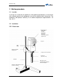
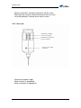
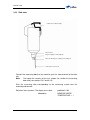
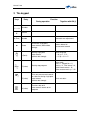
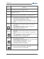
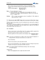
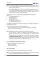
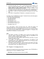
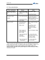
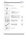
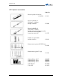
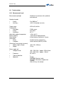
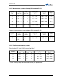
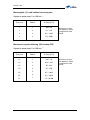
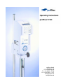
Operating instructions
proRheo R 180
proRheo GmbH
Bahnhofstr. 38
D-75382 Althengstett
Tel.: +49 (0)7051 / 77176
Fax.:+49 (0) 7051 / 77187
[email protected]
www.proRheo.de
Manual R 180
1
2
3
4
5
6
Introduction.....................................................................................................................3
Startup procedure...........................................................................................................4
2.1
Location...................................................................................................................4
2.2
Installation...............................................................................................................4
2.2.1
Front view .........................................................................................................4
2.2.2
Rear view ..........................................................................................................5
2.2.3
Side view...........................................................................................................6
The keypad......................................................................................................................7
Settings ...........................................................................................................................9
4.1
Language.................................................................................................................9
4.2
Code for instrument settings and other measurement systems .........................9
4.2.1
Instrument settings ............................................................................................9
4.2.2
Other measurement systems ..........................................................................11
4.2.3
Baud rate ........................................................................................................11
4.3
Status record.........................................................................................................12
Measurements ..............................................................................................................12
5.1
Thermostating .......................................................................................................12
5.2
Zero adjustment ....................................................................................................12
5.3
Measurement mode HAND: Single point measurement without data storage .13
5.3.1
Procedure .......................................................................................................13
5.3.2
Terminating a single point measurement.........................................................14
5.3.3
Time interval....................................................................................................14
5.3.4
Printing out data ..............................................................................................15
5.4
Measurement mode AUTOMATIK: Step programs with data storage ...............15
5.4.1
Single point measurement with data storage ...................................................16
5.4.2
Procedure .......................................................................................................16
5.4.3
Programs 3...9: changing shear rates..............................................................17
5.4.4
End of the measurement .................................................................................18
5.4.5
Printing out data ..............................................................................................18
5.4.6
Deleting measurement data ............................................................................18
5.4.7
Data transfer ...................................................................................................19
Appendix .......................................................................................................................19
6.1
Maintenance ..........................................................................................................19
6.1.1
Cleaning instrument parts................................................................................19
6.1.2
Calibrating and testing.....................................................................................20
6.2
Errors and malfuntions.........................................................................................21
6.3
Accessories...........................................................................................................22
6.3.1
Standard accessories in case..........................................................................22
6.3.2
Optional accessories .......................................................................................23
6.4
Technical data .......................................................................................................24
6.4.1
Measurement head .........................................................................................24
6.4.2
Measurement systems following DIN standard 53 019 ....................................25
6.4.3
Relative measurement systems.......................................................................25
6.4.4
Step programs.................................................................................................27
6.4.5
RS232 interface definition ...............................................................................28
6.4.6
Printer .............................................................................................................28
Version 03.09
2
Manual R 180
1 Introduction
The proRheo R 180 is used for the simple determination of the viscosity of a wide
range of substances in the lab or field. It is equipped with a rechargeable battery that
allows it to be operated for approx. one hour at full load without connection to the
power supply.
The proRheo R 180 is a rotational viscometer. Its open, concentric measurement
system allows measurements by immersion. The measuring head and measuring tube
are rigidly coupled; the measuring unit is driven by a direct-current motor.
A built-in microprocessor calculates the values for the viscosity with the aid of the
measured torque, the set shear rate and the measurement system used. The sample
temperature is measured by a Pt 100 sensor immersed in the substance.
The display shows you the following data:
the sample temperature T in °C,
the torque M in mN.m,
the shear rate D in s-1,
the shear stress (tau) in Pa,
the calculated viscosity (eta) in Pa.s,
the measurement system, e.g. 11,
the program step, e.g. 6 during an automatic step measurement.
The proRheo R 180 can store 50 measurements of step programs or single point
measurements. An attached printer records the measurement data. With the aid of the
rhesy 80 evaluation software, measurement data can be transferred to an attached
computer and evaluated thus allowing the proRheo R 180 to be incorporated in
computer-aided data acquisition systems. The rhesy 80 control and evaluation
software allows you to perform computer-aided measurements.
Version 03.09
3
Manual R 180
2 Startup procedure
2.1
Location
In the lab, the stand with the proRheo R 180 should be positioned on a level bench
with sufficient space for the peripherals that will be attached and a thermostat. The
proRheo R 180 operates faultlessly in an ambient temperature range between + 10
and +40 °C.
2.2
Installation
2.2.1 Front view
Digital display for:
- temperature
- viscosity
- shear stress
- shear stress
- shear rate
- measurement system
- program step
Key pad
ON
OFF
Stand arm unit with
locking screw
Locking screw for instrument
Control slit
(substance level)
Standrod
Measuring system,
Comprising measuring bob
and measuring tube
Stand base with adjustment screw
(for uneven suraces)
Version 03.09
4
Manual R 180
-
Position stand rod in stand base and secure with the screw.
Slide stand arm unit over stand rod and secure with the screw
Install the proRheo R 180 and secure with the screw
2.2.2 Rear view
Serial interface (RS232C)
Connector for computer
Parallel interface (Centronics)
Connector for printer
Connector for line supply
and charger
-
Connect to the power supply
Attach a printer as appropriate
Attach a computer as appropriate
Version 03.09
5
Manual R 180
2.2.3 Side view
Handle (for use without stand)
Grip for stand
Bayonet coupling for measuring tube
Drive axis with bayonet coupling for measuring bob
Temperature sensor Pt 100
-
Connect the measuring bob that you need for your first measurement to the drive
axis.
Note:
The higher the viscosity of the test sample, the smaller the measuring
bob used (see sections 6.4.2 and 6.4.3).
-
Push the measuring tube corresponding to the measuring system over the
mounting and connect.
-
Switch on the instrument. The display must show:
followed by:
Version 03.09
proRheo R 180
MEASURE MODE?
TEMPERATURE **. *.
6
Manual R 180
3 The keypad
Keys
1 ….. 9
E
0 (Zero)
←
Entry
During operation
Function
Together with ON (I)
Numbers
Confirm
Number
Delete
• (Point)
C (Letter)
B (Letter)
A (Letter)
Version 03.09
Automatic zero adjustment
Terminates single point
measurement (without data
storage)
Deletes data of all
measurement records
Starting single point
measurement
(without data storage)
Select language
E = 0, g = 1, f = 2,
it = 3, sp = 4, hi = 5
Starting step programs
Select code
Date = 1, Sample No. = 2,
Density = 4, Time interval = 6,
Quick measurement = 16,
Other measurement sys. = 32
Prints out measurement records
or a data line during single point
measurement
(without data storage)
Prints out status
Transfers data of all
measurement records to the
computer
7
Manual R 180
Key(s)
Numbers
E
0 ( zero)
Function
Entry of numeric values, code or program numbers.
Confirmation of an entry.
Select Zero adjustment (see section 5.2)
Simultaneously press this key when switching on: the display shows...› 0 ‹…
•
•
•
Hand
•
•
•
•
Automatic
•
•
Printer
Computer
Version 03.09
•
•
Delete data (see section 5.4.6)
Simultaneously press this key when switching on: all data of stored
measurements are deleted (display:…CLEAR…..)
With entry of letters/numbers, deletes from right to left.
Terminates the single point measurement in the measurement mode
HAND.
Select language (see section 4.1)
Simultaneously press this key when switching on: the displa shows
LANGUAGE.
Select single point measurement (without data storage): when
MEASURE MODE? is shown on the display.
<8Decimal) point during the entry.
Select code for instrument settings and own measurement systems (see
section 4.2)
Simultaneously press this key when switching on: the display shows
CODE
Select step programs or single point measurement (with data storage)
when MEASURE MODE? is shown on the display.
Letter C during the entry of a sample number.
•
•
•
Print out status (see section 4.3)
Simultaneously press this key when switching on: the instrument settings
stored in the proRheo R 180 are printed.
Prints out a data line in the measurement mode HAND.
Prints out the stored measurement data.
Letter B during the entry of a sample number.
•
•
Transfers the measurement data after a step porgram.
Letter A during the entry of a sample number.
8
Manual R 180
4 Settings
4.1
Language
When you switch the proRheo R 180 on for the first time, the display is in English. To
ensure that the text appears in the language most appropriate to your needs, you are
offered a choice of 6 languages. Exceptions are the words LANGUAGE, CODE, TRY
AGAIN and CLEAR.
-
-
Press the hand key and at the same time switch the instrument on:
LANGUAGE: appears on the display.
Enter one of the following numbers for your language:
0
English
1
Deutsch
2
Francais
3
Italiano
4
Espanol
5
Nederlands
Press the E key to confirm the entry.
Your language is stored by the proRheo R 180 until you define a different one.
4.2
Code for instrument settings and other measurement systems
4.2.1 Instrument settings
With the entry of a code, you can set the following features of the proRheo R 180. The
proRheo R 180 stores the corresponding configuration until you define a new code.
Record date (sub-code 1):
Each measurement is recorded with a date.
The stored date is displayed before every measurement.
• If it is current, you can confirm with E, otherwise you must first overwrite it with
the current date (max. 8 digits).
Note: To enable the evaluation software to recognize entry of the date, you
must enter it in the format xx.yy.zz.
Record sample number (sub-code 2):
Each measurement is recorded with a sample number.
Entry of a sample number is requested before every measurement; input format: max.
16 characters.
Version 03.09
9
Manual R 180
Calculate kinematic viscosity (sub-code 4):
In each measurement the measured dynamic viscosity is divided by the inputted
density to calculate the kinematic viscosity; this is displayed and recorded.
Entry of the density is requested before every measurement.
The kinematic viscosity v (ny) is the quotient of the dynamic viscosity
density (rho): v = /
(eta) and the
Note: The density (rho) is entered in g/mL. The calculated kinematic viscosity v (nu)
appears in the display field of (eta) and has the unit 10-3 m2/s. Its value is also
printed out in the unit 10-3 m2/s in the VISCOSITY column.
Calculation of the kinematic viscosity is meaningful only if the dynamic viscosity
is absolute (measurement with DIN measurement systems).
Time interval measurement (sub-code 8):
In the HAND measurement mode (single point measurement without data storage) the
values remain in the display for the inputted time interval (stopwatch function). If a
printer is attached, the current viscosity is printed out in accordance with the time
interval. This allows you to determine the viscosity as a function of time, e.g. with
thixotropic or reactive samples.
Before every measurement, the stored time interval is displayed and you can either
confirm it with E or overwrite it.
Quick single point measurement (sub-code 16):
In the HAND measurement mode (single point measurement without data storage),
the torque is measured for approx. 1 second at all shear rates.
If measured values determined in this manner are not sufficiently stable at low
rotational speeds, you should not set sub-code 16; in such a case the measurements
last longer at a lower shear rate (D < 80 s-1), e.g. approx. at D = 6,5 s-1.
You can determine the instrument settings by entry of a code comprising the sum of
the respective sub-codes.
-
Press the automatic key and at the same time switch on the instrument.
CODE: appears on the display.
0
1
2
4
8
16
Version 03.09
None of the instrument settings active
Date
Sample number
Density
Time interval in s for single point measurements
Quick single point measurement
10
Manual R 180
Example:
a.
b.
-
If you wish to enter the date (1) and the sample number (2),
enter 3 (= 1 + 2).
With code 31 you activate all instrument settings.
Press the E key to confirm the entry.
The display shows:
MEASURE MODE?
TEMPERATURE **. *
4.2.2 Other measurement systems
You can use measurement systems that are not listed in accessories (section 8) if you
store these under a number in the proRheo R 180. To ensure that the proRheo R 180
calculates the correct shear rate and shear stress for these measurement systems,
you have to determine and enter the appropriate conversion factors. These factors are
stored.
-
Press the automatic key and at the same time switch the instrument on.
CODE: appears on the display.
-
Enter 32 and confirm with E.
SYSTEM No.:
The numbers 90...97 are available for your own measurement systems.
-
Enter number and confirm with E.
kD:
-
Enter the conversion factor for the shear rate (kD) and confirm with E; the proRheo
R 180 calculates this using the formula:
kTAU:
-
Enter the conversion factor for the shear stress (kTau) and confirm with E; the
proRheo R 180 calculates this using the formula:
= kTAU . M (M: torque)
in Pa
Note: You can always overwrite the number and factors of a measurement system by
reentering the appropriate numbers/values using the above procedure.
4.2.3 Baud rate
You can choose the baud rate between 2400 and 9600 baud.
-
Press the automatic key and at the same time switch the instrument on.
CODE: appears on the display.
Version 03.09
11
Manual R 180
-
Enter 33 and confirm with E.
Baud rate:
-
Enter 2400, 4800 or 9600 confirm with E.
4.3
Status record
You can have a printout of the language, instrument settings, your own measurement
systems with the appropriate conversion factors and the step programs 3...9 with the
appropriate shear rates (see section 6.3) that are stored in the proRheo R 180.
-
Press the printer key and at the same time switch the instrument on: you obtain the
status record.
Note: a. The "+" and "_" signs under the code number show which sub-codes have
been selected: "+" = selected, "-" = not selected.
b. Measurement systems with kD and kTau = 0 have not been programmed.
5 Measurements
5.1
Thermostating
You can use a commercial thermostat for thermostating.
-
Close the measuring tubes with the caps and then immerse as far as possible in
the thermostat bath ensuring that the thermostating medium can not splash into the
substance.
The fill level of the measurement system should be as high as possible so that the
temperature sensor is deeply immersed in the substance. Inside of the measuring
tubes a filling mark (small groove) indicates the filling volume for a DIN measurement
system without the measuring bob (take into account the thermal expansion of the
thermostating medium and of the substances being measured).
With temperatures above 50 °C, you should take into consideration the heat losses
due to air circulation around the measurement system as well as condensation. We
advise covering the top of the thermostat bath around the measuring tube.
5.2
Zero adjustment
You should perform a zero adjustment with the measurement system in the absence
of sample every day and after each change of the measurement system. The zero
adjustment must be done under the same operating status as the following
measurements. (Batterie or power supply operation).
Version 03.09
12
Manual R 180
-
Press the key 0 (zero) and simultaneously switch on the proRheo R 180.
As long as the instrument executes the zero adjustment, the display shows
...> 0 <...
Then the follwing appears:
MEASURE MODE?
TEMPERATURE **.*
Note: a. The zero adjustment is stored.
b. Whenever possible, you should perform the zero adjustment after the
instrument has warmed up. Allow the proRheo R 180 to run at a shear rate
of 50 s-1 for approx. 30 s.
Caution:
5.3
With an empty measurement system, the proRheo R 180 should not
rotate faster than D = 200 s-1
Measurement mode HAND: Single point measurement without data storage
Select this type of measurement if you wish to determine the viscosity of the sample at
one shear rate.
The proRheo R 180 does not store the measured data of this measurement mode! To
store single point measurements, you must perform these under the AUTOMATIC
measurement mode (see section 5.4.1).
5.3.1 Procedure
-
Immerse measurement system without cap in the sample or add the sample to the
closed measurement system (fill volume: see section 6.4.2).
-
Switch the proRheo R 180 on and wait until the display shows: MEASURE MODE?
TEMPERATURE*.*
Note: If you have to thermostat the sample, wait until the desired temperature is
displayed before starting the measurement (see section 6.4).
-
Press the hand key.
-
Enter the measurement system and confirm with E.
-
Enter the values/designation of the subsequent instrument settings that you have
selected (see section 5.1) and confirm with E in each case.
Note: If you confirm DENSITY with E without entering a value, the message
TRY AGAIN appears.
SHEAR RATE:
Enter a value appropriate to the sample and confirm with E.
-
Version 03.09
13
Manual R 180
Note: a. The values/numbers for interval, measurement system and shear rate are
stored, so that for the next measurement you can either confirm these with E or
enter new values/numbers.
b. The shear rate range is 6.5...1291 s-1 for the DIN measurement systems 11,
22 and 33 (for other measurement systems, see section 6.4.2). If you enter a
number outside this range, SHEAR RATE immediately reappears on the
display to allow the "correct" value to be entered.
The measurement starts. You are shown the following data on the display after
approx. 5 s:
•
the sample temperature T in °C
•
the torque M in mN.m
•
the shear rate D in s-1
•
the shear stress in Pa
•
the calculated viscosity in Pa.s
•
the measurement system, e.g. 11.
The proRheo R 180 acquires several measured values per second and displays the
recalculated mean values.
During the measurement you can change the shear rate:
-
Press one of the numeric keys (1 to 9): SHEAR RATE appears in the display.
-
Enter new value and confirm with E.
Note: If the torque is too large (>10 mNm), you are shown the message:
M TOO HIGH (M = torque). In operation with the power supply unit, the
proRheo R 180 switches itself off at a torque of approx. 11 mNm (see section
8).
You can either enter a lower value for the shear rate or, if possible, use a more
suitable measurement system.
If the torque is too low (‹0,25 mNm), you are shown the message: M TOO
LOW. In this case you can enter a larger value for the shear rate or use a more
suitable measurement system (see sections 6.4.2 or 6.4.3).
5.3.2 Terminating a single point measurement
To terminate a single point measurement, either
press the arrow key or
switch off the instrument.
-
5.3.3 Time interval
If you have attached a printer, the recalculated viscosity is printed out.
Note: a. The time intervals outputted by the printer do not always coincide with the
inputted value owing to rounding and the time response.
Version 03.09
14
Manual R 180
b. With low shear rates, the measurement time can be larger than the inputted
time interval. If this interferes: Select quick single point measurement as an
instrument setting (sub-code 16, see section 4.2.1).
c. If no printer is attached, the display stops after the interval time has elapsed
until you switch the instrument off or attach a printer (stopwatch function).
5.3.4 Printing out data
If you have attached a printer and have selected INTERVAL, the data are printed out
online (see section 4.2). The instrument settings you have selected and whose value
you have entered are printed out as a title. Exceptions are the titles DATE and
SAMPLE NO., which are always printed out.
If you have not selected INTERVAL or have entered 0 (zero) as its value, you can
press the printer key during the measurement: the data currently displayed are printed
out.
5.4
Measurement mode AUTOMATIK: Step programs with data storage
Select this measurement mode if you wish to use step programs to measure the
viscosity of the sample at several shear rates. The samples are automatically
measured at 8 different shear rates and the results are stored. You can use the
resulting data to plot a flow curve to characterize the sample.
As a special case, you can perform single point measurements in this measurement
mode to store your data (see below).
You have a choice of 10 programs:
Program
0
Definition
You can enter the lowest and highest shear rate (D MIN, D MAX)
The proRheo R 180 calculates the linear intermediate steps. D MIN
and D MAX of program 0 are not stored, but the results are.
You can use this program for rapid scanning of a shear rate range to
determine the suitable D MIN/ D MAX values for further
measurements.
1
Measurement is performed at rotational speeds between
50...1000 min-1 in geometric steps (see section 6.4.4). You can not
change this program.
2
Measurement is performed at rotational speeds between
5...100 min-1 in geometric steps (see section 6.4.4). You can not
change this program.
3-9
Version 03.09
You can enter the lowest and highest shear rate (D MIN, D MAX) for
7 programs. (D MIN, D MAX) remain stored for every program. The
proRheo R 180 calculates the linear or geometric intermediate
steps in each case. You can change and print out these programs
15
Manual R 180
(see sections 5.4.3).
5.4.1 Single point measurement with data storage
If you enter the value 0 (zero) for D MAX in the step programs 0 or 3...9, a single point
measurement with data storage follows.
The measurement is performed with a shear rate D = D MIN. The measurement time
is 15 s with the mean value being calculated from the measurements during the last
10 s.
5.4.2 Procedure
Immerse measurement system without cap in the sample or add the sample to the
closed measurement system (fill volume: see section 10.2).
Switch the proRheo R 180 on and wait until the display shows:
MEASURE MODE?
TEMPERATURE **. *
Note: If you have to thermostat the sample, wait until the desired temperature is
displayed before starting the measurement (see section 6.4).
-
-
Press the automatic key.
-
Enter the measurement system and confirm with E.
-
Enter the values/designation of the subsequent instrument settings that you have
selected (see section 4.2.1) and confirm with E in each case.
Note:
a. If you confirm DENSITY with E without entering a value, the message TRY
AGAIN appears.
b. The measurement system remains stored so that for the next measurement you
either can confirm it with E or enter a new number.
PROGRAM No.:
-
-
Enter the desired number and confirm with E.
If you have selected program 1...9, the proRheo R 180 immediately starts the
measurement. If you have entered 0, the display shows:
DMIN:
Enter the initial shear rate and confirm with E.
D MAX:
Enter the final shear rate and confirm with E.
Note:
a. If no shear rates have been entered for the programs 3...9 the display shows
D MIN followed by D MAX.
Version 03.09
16
Manual R 180
b.
c.
d.
e.
The shear rate range is 6.5 ... 1291 s-1 for the DIN measurement systems 11, 22
and 33 (for other measurement systems, see section 6.4.3). If you enter a
number outside this range, D MIN or D MAX immediately reappears on the
display to allow the "correct" value to be entered.
If you enter a value for D MAX that is less than that of D MIN, the proRheo R 180
first acquires the 8 measurement points in descending then in ascending order.
With D MAX = D MIN, the 15 measurement points are aquired at the same shear
rate.
With D MAX = 0 the proRheo R 180 performs a single point measurement.
The display shows PLEASE WAIT for approx. 5 s before the measured value appears.
You can then view the following data:
• the sample temperature T in °C 0
• the torque M in mN.m
• the shear rate D in s-1
• the shear stress in Pa
• the calculated viscosity in Pa.s
• the measurement system, e.g. 11
• the program step, e.g. 6.
The R 180 acquires several measured values per second and displays the
recalculated mean values. The measurement time for a step is 10 s. The proRheo
R 180 stores the mean of the calculated values for every step in each case. Before
every step the message PLEASE WAIT is displayed for approx. 5 s. During this time,
the proRheo R 180 acquires no measured values.
Note:
a. If the torque is too large (>7.5 mNom), you are shown the message: M TOO
HIGH (M = torque). In operation with the power supply unit, the proRheo R 180
switches itself off at a torque of approx. 11 mNm.
You can either enter a lower value for D MAX or D MIN or, if possible, use a more
suitable measurement system.
b. If the torque is too high during the measurement, the proRheo R 180
automatically returns to the step preceding that which it has just reached, in other
words instead of 8 steps it performs, e.g. 6.
c. If the torque is too low (‹0,25 mN.m ), you are shown the message: M TOO LOW.
In this case you can enter a larger value for the shear rate or use a more suitable
measurement system. (see sections 6.4.2 or 6.4.3).
5.4.3 Programs 3...9: changing shear rates
If you wish to change the shear rates of one of the programs, when PROGRAM No. is
displayed you must enter the appropriate number
-
three times, e.g. 444 (you can not see the last number),
Version 03.09
17
Manual R 180
-
confirm with E,
-
enter the new value of DMIN then that of D MAX and confirm with E:
The new values are stored and the proRheo R 180 starts the measurement.
5.4.4 End of the measurement
When the measurement is at an end, the display shows:
MEMORY FREE: 23 (example)
READY
The proRheo R 180 can store the data of 50 step programs or single point
measurements.
To start the next measurement immediately, press any key (except the printer key).
The display shows:
MEASURE MODE?
TEMPERATURE **.*
5.4.5 Printing out data
In the AUTOMATIC measurement mode, the data of step programs and single point
measurements are not printed out online.
-
On completion of a measurement (or after the instrument has been switched on),
press the printer key. The proRheo R 180 immediately starts with the printout of
the last measurement and the display shows:
26 (example)
<E> ALL RECORDS
26 = number of measurements not yet printed out.
-
If you wish to have the data of all measurements that are not yet printed out, press
the E key: The proRheo R 180 continues the printout until the first stored
measurement.
-
If you wish to print out the measurement before last, press the printer key: The
measurement before last is printed out; the display shows the number of
measurements not yet printed out. You can repeat this procedure until the data of
all measurements have been printed out.
-
To start the next measurement, press any key (except the printer or E key). On the
display appears:
MEASURE MODE?
TEMPERATURE **.*
5.4.6 Deleting measurement data
To delete the stored data of all measurements, proceed as follows:
Version 03.09
18
Manual R 180
-
switch off the proRheo R 180.
-
Press the arrow key and simultaneously switch it back on: during the clearing of all
measurement data, the display shows: ---CLEAR---
5.4.7 Data transfer
You can transfer the measurement data if you have loaded the Rhesy A evaluation
soft- ware or the Rhesy S control and evaluation software on your computer. If you
press the computer key at the end of every measurement, the data are transferred.
After the data have been transferred, the display shows:
MEASURE MODE?
TEMPERATURE *.*
in other words, you can start the next measurement.
Note: If, after several measurements, you transfer the data of the last measurement,
the data of all measurements stored up to this point are always transferred. If
you switch off the proRheo R 180and press the computer key after switching it
back on, once again all stored measurements are transferred.
To avoid this, you must delete the stored data before starting a new measurement:
-
Switch off the proRheo R 180.
-
Press the arrow key and simultaneously switch it back on: during the clearing of
all measurement data, the display shows: ---CLEAR---
6 Appendix
6.1
Maintenance
Warning:
The proRheo R 180 and the power supply may be opened only by
qualified service engineers!
6.1.1 Cleaning instrument parts
-
If the measuring head, drive shaft coupling or stand are really dirty or badly
contaminated, clean only with a cloth moistened with soapy water, gasoline or
alcohol.
-
To clean the measuring head and measuring tube, always uncouple these from the
proRheo R 180!
-
You can use appropriate solvents for the measurement systems.
-
Never place the O-rings of the caps in organic solvents! Lightly grease them with
silicone grease.
Version 03.09
19
Manual R 180
O-rings material: NBR/butadiene-acrylonitrile elastomer
Internal diameter/cord thickness: 26/3 mm, 20/3 mm, 9/3 mm
6.1.2 Calibrating and testing
The proRheo R 180 can be calibrated only by proRheo service. Special instruments
and specialized knowledge are required.
To test whether the instrument is measuring properly and/or proper measurements
have been performed, you can use calibration oils for viscosity measurements.
Another possibility is to measure a suitable substance with the proRheo R 180 after
purchase or a calibration and test the instrument with the same substance at regular
intervals under identical measurement conditions (particularly at the same
temperature). You should obtain the same result. This method allows you to determine
whether the instrument has undergone any change.
•
Suitable substances are those whose viscosity behavior does not change over a
lengthy period of time (e.g. motor oils, silicon oil, paraffin). You should keep
ample quantities of such an oil on stock and use it only once for the
measurement; in other words, do not pour the substance back in the bottle on
completion of the measurement!
•
Substances exhibiting Newtonian behavior are preferable (there should be a
straight line between several measurement points and the zero point). Glycerol
(hygroscopic) and water (viscosity too low) are unsuitable.
Version 03.09
20
Manual R 180
6.2
Errors and malfuntions
Error / malfunction
The lamp of the power
supply unit does not light
up
-
-
The display showes
› READY
-
The proRheo R 180
switches itself off
-
Reason
Action
Not attached to power Check power supply
supply or power supply
defective
Call proRheo Service
The entries are wrong Switch off the R 180 and
or not stored correctly simulataneously press the
hand key. Reselect or
reenter language and code
Internal buffer battery Call ProRheo service
is discharged
The battery is
Attach the R180 to the
discharged (battery
power supply and charge
operation only)
battery
-
Battery faulty
Call proRheo service
(instrument can be
operated using power
supply)
-
Power supply unit
disconnected from
power supply
Attach to the power supply
-
Torque too high (with
single point
measurement)
On restart, either enter
lower value for shear rate
or select a smaller
measuremt system
-
Torque too high (with
step program)*
On restart, enter lower
value for D MAX
* After an increase in the speed (shear rate), a test is first performed to check that the
torque is lower than 10 mNm. If it is higher, all later steps are skipped. If, however, e.g.
in step 6 a torque of 10 mNm is almost reached, the next speed is tested. If the
difference between the steps is large, the torque can be so high that the instrument
switches itself off in operation with the power supply unit or when the battery is almost
completely discharged.
Version 03.09
21
Manual R 180
6.3
Accessories
6.3.1 Standard accessories in case
Order No.
Measuring instrument
Stand, comprising
Stand base with adjustment screw
Stand rod
Stand arm with locking screw
Measurement system of stainless steel,
comprising:
Measuring bob 1 (Ø 30 mm, l = 45 mm)
Measuring bob 2 (Ø 24 mm, l = 36 mm)
Measuring bob 3 (Ø 14 mm, l = 216 mm)
112820
112821
112822
Measuring tube 1 (Ø 32,54 mm)
Measuring tube 2 (Ø 26,03 mm)
Measuring tube 3 (Ø 15,8 mm)
112932
112937
112938
Cap 1 (for measuring tube 1)
Cap 2 (for measuring tube 2)
Cap 3 (for measuring tube 3)
112872
112877
112878
Power supply
Version 03.09
22
Manual R 180
6.3.2 Optional accessories
Order No.
Measuring tube of aluminium
set of 100
111 931
Measuring bob No. 4
(Ø 14mm, l = 10,5mm)
for high viscosities
111 906
Measuring bob No. 9
(Ø 31,5mm, l = 45mm)
for high shear rates and low viscosities
(forms with measuring tube 1
measuring system 19)
111 875
Double slit system MS 0
for low viscosities
112 823
Measurement systems ISO 2555 (set)
111 948
Measurement system TV (set)
Version 03.09
111 949
Software Rhesy 180 T
Software Rhesy 180 A
Software Rhesy 180 S
4000605
4000608
4000610
Cable RS 232
Cable USB
4010920
4010922
23
Manual R 180
6.4
Technical data
6.4.1 Measurement head
Measurement principle
Rotational viscosimeter with cylindrical
measurement
Rotational speed
•
•
Range
Accuracy :
Torque range
Temperature
•
Recording
•
Range
•
Resolution
Admissible ambient temperature
Battery capacity
Data memory
Data output
•
Printer
•
Computer
Dimensions (measuring instrument)
•
Width x depth x height
•
Weight
Power supply unit
•
Voltage/Current
•
•
•
Frequency
Type of protection
Approvals
Version 03.09
5 to 1000 min-1
± 0,5% of inputted set value
0,25 to 10,0 mN.m
Pt100 sensor
0 to 120°C
0,2 °C
+10 to +40 °C
1 hour with full load operation
Lithium battery, lifetime min. 3 years
Parallel interface (Centronics)
Serial interface (RS232) or USB
105 x 135 x 350 mm
2,2 kg
100 - 120 V±10% / approx. 320 mA and
220 - 240 V±10% / approx. 160 mA
50 - 60 Hz
I
Europe
EN 60950 Electrical safety
EN 55022 Interference suppression
Canada
CSA 22.2 No. 151-M1986
24
Manual R 180
6.4.2 Measurement systems following DIN standard 53 019
Tube
∅ mm No.
Bob
∅ mm No.
Shear Rate
[s-1]
Viscosity
[Pa.s]
Fill
volume
[ml]
11
32,54
1
30
1
6,5 – 1291
0,003 – 5,10
Ca. 24
22
26,03
2
24
2
6,5 – 1291
0,005 – 40,0
Ca. 16
33
15,18
3
14
3
6,5 - 1291
0,025 – 200
Ca. 9
19
32,54
16,1 – 3230
0,002 – 7,8
Ca. 18
System
No.
31,5
9
Double slit measurement system following DIN standard 54 453
System
50
Tube
∅ mm
28
32,54
Bob
∅ mm.
25,81
30
Shear rate
[s-1]
Viscosity
[Pa.s]
Fill
volume
[ml]
6,5 – 1291
0,001 – 6,4
Ca. 38
6.4.3 Relative measurement systems
Mesuring bob 2, 3 and 4 with measuring tube 1
Tube
∅ mm
No.
Bob
∅ mm
No.
12
32,54
1
24
13
32,54
1
14
32,54
1
System
Shear rate
[s-1]
Viscosity*
[Pa.s]
2
1,7 -354
0,02 – 121
14
3
0,8 – 152
0,14 – 1090
14
4
0,8 - 152
0,27 – 2180
* These viscosity ranges are measured and are just approximate!
Version 03.09
25
Manual R 180
Mesuring bob 1,2,3 and 4 without measuring tube
Rotational speed range: 5 to 1000 min –1
System no.
.
Bob no.
Viscosity [Pa.s]
1
1
0,05 –80
2
2
0,1 – 185
3
3
0,2 – 1300
4
4
0,4 - 2000
With these systems
the speed n is shown
instead of the shear
rate D.
Mesurement systems following ISO standard 2555
Rotational speed range: 5 to 1000 min –1
System no.
.
Bob no.
Viscosity [Pa.s]
61
1
0,01 – 26
62
2
0,02 – 105
63
3
05 – 265
64
4
0,1 – 530
65
5
0,2 – 1060
66
6
0,4 – 2650
67
7
1,5 – 10.600
Version 03.09
With these systems
the speed n is shown
instead of the shear
rate D.
26
Manual R 180
Measurement systems TV
Rotational speed range: 5 to 1000 min –1
System no.
.
Bob no.
Viscosity [Pa.s]
71
1
0,01 – 10
72
2
0,02 - 105
73
3
0,1 - 530
74
4
0,5 - 2400
75
5
1,5 - 9300
With these systems
the speed n is shown
instead of the shear
rate D.
6.4.4 Step programs
Step - Program 1
Step - Program 2
Rotational
speed step
D [s-1]
n [min-1]
Rotational
speed step
D [s-1]
n [min-1]
1
64,6
50
1
6,46
5,0
2
99,0
76,7
2
9,90
7,67
3
152
118
3
15,2
11,8
4
233
181
4
23,3
18,1
5
357
277
5
35,7
27,7
6
549
425
6
54,,9
42,5
7
841
652
7
84,1
65,2
8
1291
1000
8
129
100
Version 03.09
27
6.4.5 RS232 interface definition
The following settings apply fort he RS232 interface
• Baud rate:
2400 to 9600 baud (see section 4.2.3)
• Data bits:
8
• Stop bits:
1
• Parity:
none
• Mode:
full duplex
Connector (DB, 25 pin, male)
Pin-Number
Signal direction
Designation
Function
2
Output
TxD
Transmit Data
3
Input
RxD
Receive Data
7
-
SGND
Signal Ground
6.4.6 Printer
Attachment via parallel interface (Centronics).
You can attach a printer using a normal printer cable (25 pin, male, Centronics).
Character set setting:
• USA or GB
• IBM emulation
Version 03.09
28