1
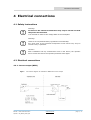
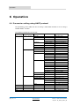
RE 250 Variable Area Flowmeter
Operating instructions
HART® communication
© MECON GmbH 04/2011 OI_RE250_HART_EN
Imprint
All rights reserved. It is prohibited to reproduce this documentation, or any part thereof,
without the prior written authorisation of MECON Flow Control Systems GmbH.
Subject to change without notice.
Copyright 2011 by
MECON Flow Control Systems GmbH - Röntgenstraße 105 - 50169 Kerpen
page 2 / 17
www.mecon.de
RE 250 – HART communication
04/2011 OI_RE250_HART_EN
Contents
Contents
1 Safety instructions ______________________________________________ 5
1.1 Intended use............................................................................................ 5
1.2 Certifications ............................................................................................ 6
2 Device description ______________________________________________ 8
2.1 Scope of delivery ...................................................................................... 8
2.2 Description code ..................................................................................... 11
3 Installation __________________________________________________ 15
3.1 Notes on installation ................................................................................ 15
3.2 Storage ................................................................................................. 15
4 Electrical connections __________________________________________ 18
4.1 Safety instructions .................................................................................. 18
4.2 Electrical connections .............................................................................. 18
4.2.1 Current output (MEM) .................................................................. 19
4.2.2 Current output with digital outputs (MEM) ....................................... 19
5 Start-up _____________________________________________________ 22
5.1 Device with current output ....................................................................... 22
5.2 Device with additional limit switches .......................................................... 23
5.3 Device with additional limit switch and pulse output ...................................... 23
6 Service______________________________________________________ 24
6.1 Maintenance .......................................................................................... 24
6.2 Retrofitting transducer MEM...................................................................... 24
6.3 Returning the device to the manufacturer ................................................... 26
6.4 Disposal ................................................................................................ 26
7 Technical data ________________________________________________ 27
7.1 Operating principle .................................................................................. 27
7.2 Technical data ........................................................................................ 28
RE 250 – HART communication
04/2011 OI_RE250_HART_EN
www.mecon.de
page 3 / 17
Safety instructions
1 Safety instructions
1.1
General information
Important!
This manual is solely a supplement to the document »Operating instructions RE250«.
To prevent any injury to the user or damage to the device it is essential that you read the safety instructions in the »Operating instructions RE250« and observe it unconditionally.
The manufacturer is not liable for any damage resulting from improper
or unintended use of these devices.
1.2
Certifications
CE marking
The manufacturer certifies for the device RE 250 with integrated transducer
MEM the fulfilment of all statutory requirements of the following EC
directives by applying the CE marking:
page 4 / 17
•
Pressure equipment directive 97/23/EC
•
Low voltage directive 2006/95/EC
•
Guideline 2004/108/EC
•
NAMUR recommendation NE21
www.mecon.de
RE 250 – HART communication
04/2011 OI_RE250_HART_EN
Device description
2 Device description
2.1 Scope of delivery
1 Flowmeter RE250 (with integrated
transducer MEM)
2 Operating Instructions
3 Certificates (optional)
4 Software
Fig 2.1
Scope of delivery
i
Information!
Please check the delivery for completeness using the packing list.
2.2 Description code
The specific output configuration of the device can be taken from the description
code:
FA
FL
FJ
With HART protocol, 4 - 20mA
With HART protocol, 4 - 20mA, 2 inductive contacts SJ 3,5N
With HART protocol, 1 inductive contact, 1 pulse output
RE 250 – HART communication
04/2011 OI_RE250_HART_EN
www.mecon.de
page 5 / 17
Installation
3 Installation
3.1
Notes on installation
i
Information!
All instruments are carefully checked for functional capability before
distribution. On receipt of the device please carry out a visual inspection of the outer packing for damage or improper handling.
Please contact the carrier and your responsible sales field service if you
should discover any defects. In such cases a description of the defect,
the type and the serial number of the device is needed.
i
i
Information!
Unpack the equipment with care to prevent damage.
Information!
All instruments are carefully checked for order conformity.
Please check the delivery for completeness using the packing list.
Please examine the flowmeter nameplate to verify that the device was
built according to your order. Particularly check devices with electrical
components for the correct supply voltage.
Information!
i
3.2
This manual is solely a supplement to the document »Operating instructtions RE250«. To prevent any injury to the user or damage to the device
it is essential that you read the installation notes in the »Operating instructions RE250« and observe it unconditionally.
Storage
● Store the device in a dry and dust-free place.
● Keep away from direct sun and heat.
● Avoid external load to the device.
● The storage temperature range for standard devices with electrical components is
about -40 … +70 °C / -40 … +158 °F.
page 6 / 17
www.mecon.de
RE 250 – HART communication
04/2011 OI_RE250_HART_EN
Electrical connections
4 Electrical connections
4.1 Safety instructions
Warning!
All work on the electrical connections may only be carried out with
the power disconnected.
It is essential to observe the voltage data on the nameplate.
Warning!
Observe all occupational safety regulations unconditionally.
Any work done on the electrical components of the device may only be
carried out by a specialist.
Caution!
After installation and any maintenance work on the device, the operator
has to check and ensure the specified protection class again.
4.2 Electrical connections
4.2.1 Current output (MEM)
Fig 4.1
Connection diagram for transducer MEM with current output
RE 250 – HART communication
04/2011 OI_RE250_HART_EN
www.mecon.de
page 7 / 17
Electrical connections
4.2.2 Current output with digital outputs (MEM)
page 8 / 17
Fig 4.2
Connection diagram for transducer MEM with 2 limit switches
Fig 4.3
Connection diagram for transducer MEM with limit switch and pulse output
www.mecon.de
RE 250 – HART communication
04/2011 OI_RE250_HART_EN
Start-up
5 Start-up
5.1 Device with current output (MEM)
The magneto-electrical measuring transducer (MEM) is completely factory-set when it
is delivered to the customer.
After applying the supply voltage to the device, initially the current output will be
about 3.5 mA to 4 mA for a few seconds. After that a current corresponding to the
pointer deflection will flow.
i
5.2
Important!
Due to the influence of the float magnet, the MEM transducer will only output
the correct current if the pointer position is caused by the float. Turning the
pointer manually will cause incorrect values, but it’s suitable for testing.
Device with additional limit switches
The limit switches are integrated into the angle transducer MEM and the design is
according to NAMUR recommendation NE21.
The switching points can be set independently over the entire measuring range by a
HART® command. For details please refer to chapter ”xx”.
i
5.3
Important!
Unless otherwise desired by the customer, the factory set value for the
switching point is about 20% / 80% of URV and the switching function is
active state »OPEN«.
Device with additional limit switch and pulse output
One of the integrated limit switches (design is according to NAMUR recommendation
NE21) can be configured as a pulse output. The pulse unit is identical to the unit of
the measured value.
The switching point of the second switch can be set independently over the entire
measuring range by a HART® command. For details please refer to chapter ”xx”.
i
Important!
Unless otherwise desired by the customer, the factory set value for the
switching point is about 40% of URV and the switching function is active
state »OPEN«.
RE 250 – HART communication
04/2011 OI_RE250_HART_EN
www.mecon.de
page 9 / 17
Operation
6 Operation
6.1 Parameter setting using HART protocol
The parameter of the MEM can be set using a hand-held terminal or a PC using a
suitable HART®-modem.
The following parameters can be set:
Main menu
Level 2
Device setup
Process variables
Level 3
Level 4
Description
Flow rate
Actual flow rate
Totalizer
Diag/service
Test device
Simulation
Actual totalizer value
Self test
Self test parameters
Status
Error indication
Default values
Values for simulation
Start simulation
Basic setup
Calibration parameter
DA trim
Current output trim
Reset device
Warm start of device
TAG
TAG number
PV unit
Range values
Device information
Detailed setup
Start/stop simulation
Calibration
Unit of measured value
PV LRV
’0’
PV URV
Upper range value
PV unit
Unit of measured value
PV LSL
Lower limit for MR
PV USL
Upper limit for MR
Model
’ES’
Device ID
Unique device ID
TAG
TAG number
Date
Calibration date
Write protect
’NO’
Descriptor
Description of device
Message
Brief message
Revision #
Revision number
Xfer function
’Linear’
PV damp
Time constant
Totalizer
Totalizer function on/off
Low flow cutoff
Namur
Cutoff value in %
MAX
MAX value in % of URV
MIN
MIN value in % of URV
Switch function
Switch
N1-N2, MIN-MAX, …
Active state open/closed
PV
Measured value
PV AO
Anaolg output (corresp.)
LRV
Lower range value
URV
Upper range value
page 10 / 17
www.mecon.de
RE 250 – HART communication
04/2011 OI_RE250_HART_EN
Operation
RE 250 – HART communication
04/2011 OI_RE250_HART_EN
www.mecon.de
page 11 / 17
Service
7 Service
7.1 Maintenance
The devices were built within the scope of low maintenance but periodically the flowmeters should be inspected for signs of corrosion, mechanical wear as well as damage to the fitting and the display unit.
We advice to carry out inspections at least once a year.
For a detailed inspection and cleaning the device must be removed from the piping.
Caution!
Appropriate safety precautions have to be taken when removing the device.
Always use new gaskets when reinstalling the device in the piping.
7.2 Retrofitting transducer MEM
Devices with measuring ring
For devices with standard measuring ranges starting from 5-50 l/h (gases: 0.15 – 1.5
m³/h) the float damping can be replaced by the customer:
● Remove the device from the piping.
● Fix the device, ensuring that the fitting will not be damaged.
● The damping cylinder † is fixed by retaining clamps …. Bend up these two clamps
carefully using a suitable tool.
1 Float with damping
2 Upper
guide
bracketa
● Move the damping cylinder a little bit to the bottom end of the
fitting,
make
quarter turn and take the cylinder out of the fitting.
3 Self-locking nut
● Insert the new damping cylinder into the fitting from the top,4 slide
it over
the
Lower guide
bracket
damping part of the float and arrange it into the retaining clamps.
5 Retaining clamp
● Fix the cylinder by bending the retaining clamps together.
6 Damping cylinder
● Fit the device back into the piping.
page 12 / 17
www.mecon.de
RE 250 – HART communication
04/2011 OI_RE250_HART_EN
Service
7.3 Returning the device to the manufacturer
This device has been carefully manufactured and tested. Should you nevertheless
need to return a device to MECON GmbH please observe the following points:
Caution!
According to the actual waste disposal directives, the owner/customer is
responsible for the waste management of hazardous and toxic waste.
For reasons of environmental protection and safeguarding the health and
safety of our personnel all devices sent to MECON GmbH to be
repaired must be free of toxic and hazardous substances. This
also applies to cavities of the devices. If necessary the customer
is kindly requested to neutralize or rinse the devices before
returning to MECON.
The customer has to confirm this by filling in an appropriate form which
is available for download on the MECON website:
www.mecon.de/en/declaration/contamination.pdf
Caution!
In the case of returning devices, despite these requirements, which
contain hazardous and toxic substances, Mecon GmbH is entitled to
dispose these substances at the cost of the customer without any further
inquiries.
7.4 Disposal
Caution!
Disposal of the devices has to be carried out in accordance with relevant
legislation in your country.
RE 250 – HART communication
04/2011 OI_RE250_HART_EN
www.mecon.de
page 13 / 17
Technical data
8 Technical data
8.1 Operating principle
Like other devices of this series the variable area flowmeter RE250 operates on the
principle of flotation:
The measuring unit consists of a metal tube with a measuring ring in which a float
can move up and down. The movement of the float is transmitted via a magnet to a
subsequent magnet which is mounted on the pointer axis.
The position of this magnet is detected by a Hall-sensor inside the integrated angle
transducer MEM (sensor signals A, B) and generates a resulting output current of
4...20mA. The signal is linearised with a maximum of 16 sampling points in the
process.
Fig. 7.1
page 14 / 17
Operating principle of the RE250
www.mecon.de
RE 250 – HART communication
04/2011 OI_RE250_HART_EN
Technical data
8.2
Technical data
General data
Range of application
Flow measurement of liquids and gases
Measuring principle
Flotation / Float measuring
Orientation
Vertical – flow direction from bottom to top
Measuring accuracy*
Directive
VDI / VDE 3513, sheet 2 (qG = 50%)
Liquids
G 1.6 (add. 0,2 %** of URV for MEM)
Gases
G 2.0 (add. 0,2 %** of URV for MEM)
Reproducibility
0,5 % of URV (add. 0,1 % of URV for MEM)
* A variation of the operating temperature to the considered temperature for the calibration process, will
lead to a corresponding inherent error
** For ambient temperatures < -20 °C the measuring error will increase
Temperatures
Device version
Ambient temperature*
Storage temperature
[°C]
[°F]
[°C]
[°F]
with 4 … 20 mA + HART® protocol
-40 …+70
-40 …+158
-40 …+70
-40 …+158
with 4 … 20 mA + HART® + binary outputs
-40 …+70
-40 …+158
-40 …+70
-40 …+158
* Danger!
For applications in hazardous areas it is mandatory that the temperature
class of the type examination certificate (protection type) will be regarded additionally.
For devices used in hazardous areas, additional safety notes apply; please
refer to the Ex documentation!
RE250 with current output 4 …20 mA and HART® protocol
Cable gland
M20 x1.5
Terminal connection
2.5 mm²
Auxiliary supply voltage UB
14 V … 30 V DC
Measuring signal
4 … 20 mA = 0 … 100% flow value in 2-wire technology
Power supply influence
< 0.1 % of MV
Max. external load RB
680 Ω (30 V)
Min. external load RB
250 Ω
Temperature influence
< 10 µA / K
Min. power supply
19.5V DC
HART protocol revision
5.0
Device revision
1
RE 250 – HART communication
04/2011 OI_RE250_HART_EN
RB = (UB - 14V) / 22 mA
www.mecon.de
page 15 / 17
Technical data
RE250 with current output 4 …20 mA and HART® protocol + binary outputs
Supplements to technical data for RE250 with current output 4 … 20 mA:
Binary outputs
Switching function
NAMUR (EN 60947-5-6:2000)
Max. voltage
30 V DC
Max. power consumption
100 mW
Current on state OPEN
typ. 0.4 mA
Current on state CLOSED
typ. 4 mA
Pulse output
Max. Rate
10 Hz
Pulse width
approx. 50 ms
page 16 / 17
www.mecon.de
RE 250 – HART communication
04/2011 OI_RE250_HART_EN
Technical data
Mecon GmbH
Röntgenstraße 105
D 50169 Kerpen
Tel.:
+49 (0)2237 600 06 -0
Fax.: +49 (0)2237 600 06 – 20
Email: [email protected]
www.mecon.de
OI_RE250_HART_EN
Subject to change without notice
Copyright ©