1
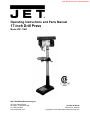
This .pdf document is bookmarked
Operating Instructions and Parts Manual
17-inch Drill Press
Model JDP-17MF
WALTER MEIER (Manufacturing) Inc.
427 New Sanford Road
LaVergne, Tennessee 37086
Ph.: 800-274-6848
www.waltermeier.com
Part No. M-354169
Revision C3 09/2013
Copyright © 2013 Walter Meier (Manufacturing) Inc.
Warranty and Service
Walter Meier (Manufacturing) Inc., warrants every product it sells. If one of our tools needs service or repair, one of
our Authorized Service Centers located throughout the United States can give you quick service. In most cases, any
of these Walter Meier Authorized Service Centers can authorize warranty repair, assist you in obtaining parts, or
perform routine maintenance and major repair on your JET® tools. For the name of an Authorized Service Center in
your area call 1-800-274-6848.
MORE INFORMATION
Walter Meier is consistently adding new products to the line. For complete, up-to-date product information, check with
your local Walter Meier distributor, or visit waltermeier.com.
WARRANTY
JET products carry a limited warranty which varies in duration based upon the product (MW = Metalworking, WW =
Woodworking).
WHAT IS COVERED?
This warranty covers any defects in workmanship or materials subject to the exceptions stated below. Cutting tools,
abrasives and other consumables are excluded from warranty coverage.
WHO IS COVERED?
This warranty covers only the initial purchaser of the product.
WHAT IS THE PERIOD OF COVERAGE?
The general JET warranty lasts for the time period specified in the product literature of each product.
WHAT IS NOT COVERED?
Five Year Warranties do not cover woodworking (WW) products used for commercial, industrial or educational
purposes. Woodworking products with Five Year Warranties that are used for commercial, industrial or education
purposes revert to a One Year Warranty. This warranty does not cover defects due directly or indirectly to misuse,
abuse, negligence or accidents, normal wear-and-tear, improper repair or alterations, or lack of maintenance.
HOW TO GET SERVICE
The product or part must be returned for examination, postage prepaid, to a location designated by us. For the name
of the location nearest you, please call 1-800-274-6848.
You must provide proof of initial purchase date and an explanation of the complaint must accompany the
merchandise. If our inspection discloses a defect, we will repair or replace the product, or refund the purchase price,
at our option. We will return the repaired product or replacement at our expense unless it is determined by us that
there is no defect, or that the defect resulted from causes not within the scope of our warranty in which case we will,
at your direction, dispose of or return the product. In the event you choose to have the product returned, you will be
responsible for the shipping and handling costs of the return.
HOW STATE LAW APPLIES
This warranty gives you specific legal rights; you may also have other rights which vary from state to state.
LIMITATIONS ON THIS WARRANTY
WALTER MEIER (MANUFACTURING) INC., LIMITS ALL IMPLIED WARRANTIES TO THE PERIOD OF THE
LIMITED WARRANTY FOR EACH PRODUCT. EXCEPT AS STATED HEREIN, ANY IMPLIED WARRANTIES OR
MERCHANTABILITY AND FITNESS ARE EXCLUDED. SOME STATES DO NOT ALLOW LIMITATIONS ON HOW
LONG THE IMPLIED WARRANTY LASTS, SO THE ABOVE LIMITATION MAY NOT APPLY TO YOU.
WALTER MEIER SHALL IN NO EVENT BE LIABLE FOR DEATH, INJURIES TO PERSONS OR PROPERTY, OR
FOR INCIDENTAL, CONTINGENT, SPECIAL, OR CONSEQUENTIAL DAMAGES ARISING FROM THE USE OF
OUR PRODUCTS. SOME STATES DO NOT ALLOW THE EXCLUSION OR LIMITATION OF INCIDENTAL OR
CONSEQUENTIAL DAMAGES, SO THE ABOVE LIMITATION OR EXCLUSION MAY NOT APPLY TO YOU.
Walter Meier sells through distributors only. The specifications in Walter Meier catalogs are given as general
information and are not binding. Members of Walter Meier reserve the right to effect at any time, without prior notice,
those alterations to parts, fittings, and accessory equipment which they may deem necessary for any reason
whatsoever. JET® branded products are not sold in Canada by Walter Meier.
2
Table of Contents
Warranty and Service ............................................................................................................................................ 2 Table of Contents .................................................................................................................................................. 3 Warning ................................................................................................................................................................. 4 Grounding Instructions .......................................................................................................................................... 6 On-Off Switch Padlock .......................................................................................................................................... 8 Introduction ........................................................................................................................................................... 9 Specifications ........................................................................................................................................................ 9 Unpacking ........................................................................................................................................................... 10 Contents of the Shipping Container .................................................................................................... 10 Before Assembly ................................................................................................................................ 10 Assembly............................................................................................................................................................. 11 Replacement Parts.............................................................................................................................................. 17 JDP-17MF Drill Press Assembly......................................................................................................... 18 Parts List............................................................................................................................................ 19 Electrical Connections........................................................................................................................ 22 3
Warning
Wear eye protection.
Always keep guards in place and in proper operating condition. Do not operate the machine
without the guards for any reason.
Support workpiece adequately at all times during operation; maintain control of work at all times.
This drill press is designed and intended for use by properly trained and experienced personnel
only. If you are not familiar with the proper and safe operation of a drill press, do not use until
proper training and knowledge have been obtained.
•
REMOVE ADJUSTING KEYS AND WRENCHES. Form a habit of checking to see that keys and
adjusting wrenches are removed from the machine before turning it on.
•
KEEP THE WORK AREA CLEAN. Cluttered areas and benches invite accidents.
•
DON’T USE IN A DANGEROUS ENVIRONMENT. Don’t use power tools in damp or wet locations,
or expose them to rain. Keep work area well lighted.
•
KEEP CHILDREN AWAY. All visitors should be kept a safe distance from the work area.
•
MAKE THE WORKSHOP KIDPROOF with padlocks, master swatches, or by removing starter keys.
•
DON’T FORCE THE MACHINE. It will do the job better and safer at the rate for which it was
designed.
•
USE THE RIGHT TOOL. Don’t force a machine or attachment to do a job for which it was not
designed.
•
USE THE PROPER EXTENSION CORD. Make sure your extension cord is in good condition. When
using an extension cord, be sure to use one heavy enough to carry the current your machine will
draw. An undersized cord will cause a drop in the line voltage resulting in power loss and
overheating. The table following shows the correct size to use depending on the cord length and
nameplate ampere rating. If in doubt, use the next heavier gauge. Remember, the smaller the gauge
number, the heavier the cord.
Total Length of Cord in Feet
0-25
25-50
AWG
16
14
•
WEAR PROPER APPAREL. Do not wear loose clothing, gloves, neckties, rings, bracelets, or other
jewelry which may get caught in moving parts. Nonslip footwear is recommended. Wear protective
hair covering to contain long hair.
•
ALWAYS USE SAFETY GLASSES. Also use face or dust masks if the cutting operation is dusty.
Everyday eyeglasses only have impact resistant lenses; they are not safety glasses.
•
DON’T OVERREACH. Keep proper footing and balance at all times.
•
MAINTAIN TOOLS WITH CARE. Keep tools sharp and clean for best and safest performance.
Follow instructions for lubricating and changing accessories.
•
ALWAYS DISCONNECT THE MACHINE FROM THE POWER SOURCE BEFORE SERVICING.
•
REDUCE THE RISK OF UNINTENTIONAL STARTING. Make sure the switch is in the off position
before plugging in.
4
•
USE RECOMMENDED ACCESSORIES. The use of accessories and attachments not
recommended by JET may cause hazards or risk of injury to persons.
•
NEVER STAND ON A MACHINE. Serious injury could occur if the machine is tipped.
•
CHECK DAMAGED PARTS. Before further use of the machine, a guard or other part that is
damaged should be carefully checked to determine that it will operate properly and perform its
intended function - check for alignment of moving parts, binding of moving parts, breakage of parts,
mounting, and any other conditions that may affect its operation. A guard or other part that is
damaged should be properly repaired or replaced.
•
NEVER LEAVE THE MACHINE RUNNING UNATTENDED. TURN POWER OFF. Don’t leave the
machine until it comes to a complete stop.
•
SOME DUST CREATED by power sanding, sawing, grinding, drilling and other construction activities
contains chemicals known to cause cancer, birth defects or other reproductive harm. Some
examples of these chemicals are:
Lead from lead based paint
Crystalline silica from bricks and cement and other masonry products, and
Arsenic and chromium from chemically-treated lumber.
Your risk from those exposures varies, depending on how often you do this type of work. To reduce
your exposure to these chemicals: work in a well ventilated area, and work with approved safety
equipment, such as those dust masks that are specifically designed to filter out microscopic particles
•
DO NOT operate tool while under the influence of drugs, alcohol or any medication.
•
DO NOT drill pieces of material that are too small to be safely supported.
•
WHEN drilling a large workpiece, provide additional support at table height.
•
ADDITIONAL INFORMATION regarding the safe and proper operation of this product is available
from the National Safety Council, 1121 Spring Lake Drive, Itasca, IL 60143-3201, in the Accident
Prevention Manual for Industrial Operations and also in the safety Data Sheets provided by the NSC.
Please also refer to the American National Standards Institute ANSI 01.1 Safety Requirements for
Woodworking Machinery and the U.S. Department of Labor OSHA 1910.213 Regulations.
•
SAVE THESE INSTRUCTIONS refer to them often and use them to instruct others.
Familiarize yourself with the following safety notices used in this manual:
This means that if precautions are not heeded, it may result in minor injury and/or
possible machine damage.
This means that if precautions are not heeded, it may result in serious or even fatal
injury.
5
Grounding Instructions
Caution: This tool must be grounded while in use to protect the operator from electric shock.
In the event of a malfunction or breakdown, grounding provides a path of least resistance for electric
current to reduce the risk of electric shock. This tool is equipped with an electric cord having an
equipment-grounding conductor and a grounding plug. The plug must be plugged into a matching outlet
that is properly installed and grounded in accordance with all local codes and ordinances.
Do not modify the plug provided. If it will not fit the outlet, have the proper outlet installed by a qualified
electrician.
Improper connection of the equipment-grounding conductor can result in a risk of electric shock. The
conductor, with insulation having an outer surface that is green with or without yellow stripes, is the
equipment-grounding conductor. If repair or replacement of the electric cord or plug is necessary, do not
connect the equipment-grounding conductor to a live terminal.
Check with a qualified electrician or service personnel if the grounding instructions are not completely
understood, or if in doubt as to whether the tool is properly grounded. Use only three wire extension
cords that have three-prong grounding plugs and three-pole receptacles that accept the tool’s plug.
Repair or replace a damaged or worn cord immediately.
115 Volt Operation
As received from the factory, your drill press is ready to run at 115 volt operation. This drill press, when
wired for 115 volt, is intended for use on a circuit that has an outlet and a plug that looks like the one
illustrated in (A). A temporary adapter, which looks like the adapter as illustrated in (B), may be used to
connect this plug to a two-pole receptacle, as shown in (B) if a properly grounded outlet is not available.
The temporary adapter should only be used until a properly grounded outlet can be installed by a
qualified electrician. This adapter is not applicable in Canada. The green colored rigid ear, lug, or tab,
extending from the adapter, must be connected to a permanent ground such as a properly grounded
outlet box, as shown in (B).
6
230 Volt Operation
If 230V, single phase operation is desired, the following instructions must be followed:
1. Disconnect the machine from the power source.
2. This JET drill press is supplied with four motor leads that are connected for 115V operation, as shown
in Figure A. Reconnect these four motor leads for 230V operation, as shown in Figure B.
3. The 115V attachment plug (A), supplied with the drill press, must be replaced with a UL/CSA listed
plug suitable for 230V operation (D). Contact your local Authorized JET Service Center or qualified
electrician for proper procedures to install the plug. The drill press must comply with all local and
national codes after the 230 volt plug is installed.
4. The drill press with a 230 volt plug should only be connected to an outlet having the same
configuration (D). No adapter is available or should be used with the 230 volt plug.
Important: In all cases (115 or 230 volts), make certain the receptacle in question is properly grounded.
If you are not sure, have a registered electrician check the receptacle.
NOTE: If 230V is needed, a 230V light bulb must be used in the lamp. Or, the lamp circuit may be
re-wired in accordance with the diagram on page 22 and a 115V bulb may continue to be used.
7
On-Off Switch Padlock
To safeguard your machine from unauthorized operation and to avoid accidental starting by young
children, the use of a padlock (not included) is highly recommended.
To lock out an on-off switch:
1. Open the padlock. See Fig. A.
2. Insert through holes in the start button. See Fig. B
3. Close the padlock.
4. Put the key in a safe place.
8
Introduction
This manual is provided by Walter Meier (Manufacturing) Inc., covering the safe operation and maintenance
procedures for a JET Model JDP-17MF Drill Press. This manual contains instructions on installation, safety
precautions, general operating procedures, maintenance instructions and parts breakdown. This machine has
been designed and constructed to provide years of trouble free operation if used in accordance with
instructions set forth in this manual. If there are any questions or comments, please contact either your local
supplier or Walter Meier. Walter Meier can also be reached at our web site: www.waltermeier.com.
Specifications
Stock Number ............................................................................................................................................. 354169
Swing ........................................................................................................................................................... 16-1/2”
Type ................................................................................................................................................................ Floor
Drilling Capacity ................................................................................................................................................ 5/8”
Chuck Size ........................................................................................................................................................ 5/8”
Spindle Travel ................................................................................................................................................ 4-3/8”
Spindle Distance to Base ................................................................................................................................... 49”
Spindle Distance to Table (max.) ................................................................................................................. 29-1/8”
Table Size Diameter ..................................................................................................................................... 13-3/4”
Table Tilt .................................................................................................................................................. + or - 45°
Spindle Taper .................................................................................................................................................. MT-2
Column Diameter ........................................................................................................................................... 3-1/8”
Number of Spindle Speeds ................................................................................................................................. 16
Range of Spindle Speeds .............................................................................................................. 200-3,630 RPM
Overall Height .................................................................................................................................................... 66”
Base Size ..................................................................................................................................... 12-1/2” x 19-5/8”
Motor ................................................................................... TEFC, 3/4HP, 1 Ph, 115/230V, prewired 115V, 60Hz
Net Weight (approx.) .................................................................................................................................... 189 lb.
Shipping Weight (approx.) ............................................................................................................................ 200 lb.
The above specifications were current at the time this manual was published, but because of our policy of
continuous improvement, Walter Meier reserves the right to change specifications at any time and without prior
notice, without incurring obligations.
9
Unpacking
Contents of the Shipping Container
1
1
1
1
1
1
1
3
1
1
4
1
1
Head Assembly
Table
Column and Bracket Assembly
Base
Owner’s Manual
Warranty Registration Card
Chuck and Chuck Key
Downfeed Handle
Table Bracket Lock Handle
Table Bracket Raising Handle
M10 x 40 Hex Cap Bolts
Arbor
Drift Key
Tools Supplied for Assembly
1
1
3mm Hex Wrench
5mm Hex Wrench
Tools Required for Assembly (not included)
1
1
17mm Box Wrench or a 6”-8” Adjustable
Wrench
Rubber mallet (or hammer with wood block)
Read and understand all
assembly instructions before attempting
assembly. Failure to comply may cause
serious injury.
Before Assembly
1. Remove the contents from the shipping
container.
2. Compare the contents of the shipping
container with the list found above. Report
any shortages or damage to your JET
distributor.
3. Clean all rust protected surfaces with
kerosene or a light solvent. Do not use
lacquer thinner, paint thinner, or gasoline.
These will damage plastic components and
painted surfaces.
10
Assembly
1. Place the base (A, Figure 1) on a level floor.
2. With a 17mm wrench attach the column
assembly (B, Figure 1) to the base (A,
Figure 1) with four M10 x 40 hex cap bolts
(C, Figure 1). Tighten firmly.
3. Thread lock handle (D, Figure 2) into the
table bracket (E, Figure 2).
Figure 1
4. Loosen the set screw (F, Figure 3) on the
raising handle (G, Figure 3) with a 3mm hex
wrench.
5. Slide the handle onto the table bracket
shaft.
6. Turn the handle until the set screw is
opposite the flat section on the shaft, and
tighten the set screw to secure the handle.
Figure 2
7. Insert the table (H, Figure 3) into the table
bracket.
8. Tighten the table lock handle (I, Figure 3).
9. With the aid of a second person, carefully lift
the head onto the column top.
Figure 3
The head assembly is heavy.
Use care when lifting onto the column.
10. Rotate head assembly until sides of the belt
cover are parallel with the sides of the base.
11. Tighten two set screws (A, Figure 4) with a
5mm wrench until they are snug.
11
12. Install three down feed handles (B, Figure 4)
into the down feed hub (C, Figure 4).
13. Thoroughly clean spindle, arbor and chuck
(A/B/C, Figure 5). Important: These three
pieces must be free of any rust protectant,
or lubricant. If they are not clean, the arbor
and chuck will fail to seat in the spindle.
14. Turn the arbor until the tang on the arbor
engages the slot at the end of the spindle.
Slide arbor up into spindle.
15. Firmly push chuck by hand onto taper of
arbor.
Figure 4
16. Make sure chuck jaws are opened all the
way until they are inside chuck body. Use a
few taps from a rubber mallet, or a hammer
and a block of wood, against the bottom of
the chuck to seat the chuck securely onto
the arbor. Do not use a steel-faced
hammer directly against the chuck.
Figure 5
Removing the Chuck and Arbor
1. Unplug machine from the power source.
2. Raise the table until it is about seven inchs
below the chuck.
3. Place a piece of scrap wood on the table,
and lower quill using the down feed handle.
4. Rotate spindle to align the key hole in the
spindle with the key hole in the quill.
5. Insert the drift key (D, Figure 6) into the
aligned slots and tap lightly. The chuck and
arbor assembly should fall from the spindle.
Figure 6
12
Adjusting the Depth Stop
To drill multiple holes at the same preset depth,
use the depth stop:
1. Use a pencil to mark the depth the bit will
drill into the workpiece (A, Figure 7).
2. With the drill bit in the chuck, lower down
feed handle to advance bit to your mark,see
Figure 7.
3. With your other hand, advance the lock nuts
(B, Figure 7) on the depth stop rod until they
are snug to the seat (C, Figure 7).
4. The drill bit will now advance to this point.
5. To release, advance the nuts counterclockwise to the top of the depth stop.
Figure 7
Changing Spindle Speeds
A spindle speed and belt arrangement chart are
found on the inside of the belt cover (D, Figure
8). Refer to this chart whenever changing
speeds. (A similar chart is shown in Figure 11.)
To change spindle speeds:
1. Unplug the machine from the power
source.
2. Loosen two bar knobs (E, Figure 8) found
on each side of the head assembly.
Figure 8
3. Rotate the tension adjuster (F, Figure 8) to
bring the motor base as close to the head
as possible.
4. Change the belts location according the
speed chart and the speed you desire.
5. Rotate the tension adjuster (F. Figure 8) to
tension the belts.
6. Tighten two bar knobs (E, Figure 8). Belts
are properly tensioned when finger and
thumb pressure midway between the two
pulleys
causes
approximately
1/2”
deflection.
13
Return Spring Adjustment
The return spring is adjusted at the factory and
should not need further adjustment.
If
adjustment is deemed necessary:
1. Unplug the machine from the power
source.
2. Loosen two jam nuts (A, Figure 9). Do not
remove.
3. Firmly hold the coil spring cover (B, Figure
9).
4. Pull out the cover and rotate until the pin (C,
Figure 9) on the return spring plate engages
the next notch in the coil spring cover. Turn
the cover clockwise to decrease tension and
counter-clockwise to increase tension.
Figure 9
5. Tighten two jam nuts (A, Figure 9). Do not
over-tighten. Nuts should not contact the
housing when tight. The jam nuts should be
tightened against each other.
Work Light
Install a light bulb, no larger than 60 watts into
the socket accessed from beneath the head.
The light bulb is controlled by the rocker switch
(D, Figure 9).
Table Tilt Adjustment
Remove the alignment pin first
and then loosen the hex cap bolt. Failure to
comply may cause the table assembly to
separate from the column and fall.
Figure 10
To tilt the table:
1. Turn nut (E, Figure 10) clockwise to pull out
the alignment pin (F, Figure 10).
2. Loosen hex cap bolt (G, Figure 10), and tilt
the table to the desired angle.
3. Tighten the hex cap bolt (G, Figure 10).
4. The alignment pin only works at 90° and
must be reinserted when the table is
returned to 90°.
14
Basic Operation
•
Always use a back-up piece of scrap wood
to cover the table. This protects both the
table and the drill bit.
•
Place material to be drilled in such as way
as to come into contact with the left side of
the column. This prevents the material from
spinning.
If the workpiece is not large
enough to come into contact with the
column, use a clamp or drill press vise that
is securely fastened to the table. Failure to
comply may cause serious injury.
•
Feed the bit into the material with only
enough force to allow the drill bit to work.
Feeding too slowly may cause burning of
the workpiece. Feeding too quickly may
cause the motor to stop and/or the drill bit to
break.
•
Generally speaking, the smaller the drill bit,
the greater the RPM required. Wood
requires higher speeds than metal. Metal is
usually drilled at slower speeds.
•
In dusty environments, frequently blow out
any dust that accumulates inside the motor.
Lubrication
Periodically lubricate the gear and the rack, the
table elevation mechanism, the splines
(grooves) in the spindle, and the teeth of the
quill with a #2 tube grease.
Figure 11
15
Troubleshooting
Trouble
Drill press will not
start.
Drill press does not
come up to speed.
Drill Press vibrates
excessively.
Probable Cause
Remedy
Drill press unplugged from wall, or
motor.
Check all plug connections.
Fuse blown, or circuit breaker tripped.
Replace fuse, or reset circuit breaker.
Cord damaged.
Replace cord.
Starting capacitor bad.
Replace starting capacitor.
Extension cord too light or too long.
Replace with adequate size and length
cord.
Low current.
Contact a qualified electrician.
Stand on uneven surface.
Adjust stand so that it rests evenly on
the floor.
Bad belt(s).
Replace belts.
Incorrect belt tension.
Adjust belt tension. See the Changing
Spindle Speeds section.
Dry spindle.
Lubricate spindle. See the Lubrication
section.
Loose spindle pulley.
Check tightness of retaining nut on
pulley, and tighten if necessary.
Loose motor pulley.
Tighten setscrews in pulleys.
Incorrect Speed.
Change to appropriate speed; see
Speed and Pulley chart.
Chips not clearing from hole or bit.
Retract drill bit frequently to remove
chips.
Dull drill bit.
Resharpen, or replace drill bit.
Feeding too slowly.
Increase feed rate.
Bit sharpened incorrectly.
Resharpen bit correctly.
Bent drill bit.
Replace drill bit.
Bit, or chuck not installed properly.
Reinstall the chuck, or bit properly.
No backing board used.
Place a scrap board underneath the
workpiece to prevent splintering.
Workpiece pinching the bit.
Support or clamp workpiece.
Excessive feed rate.
Decrease feed rate.
Chuck jaws not tight.
Tighten chuck jaws.
Improper belt tension.
Adjust belt tension. See Changing
Spindle Speeds section.
Noisy Operation.
Workpiece Burns.
Drill bit wanders.
Wood splinters on the
underside.
Drill bit binds in
workpiece.
16
Trouble
Probable Cause
Remedy
Bent drill bit
Replace drill bit.
Worn spindle bearings.
Replace spindle bearings.
Bit, or chuck not properly installed.
Reinstall the bit, or chuck properly.
Quill returns too
slowly, or too fast.
Spring has improper tension.
Adjust return spring tension
Chuck, or arbor do not
stay in place.
Dirt, grease, etc. on arbor, chuck or
spindle.
Clean all mating surfaces thoroughly
with a cleaner degreaser.
Excessive drill bit
runout or wobble.
Replacement Parts
Replacement parts are listed on the following pages. To order parts or reach our service department, call 1800-274-6848, Monday through Friday (see our website for business hours, www.waltermeier.com). Having the
Model Number and Serial Number of your machine available when you call will allow us to serve you quickly
and accurately.
17
JDP-17MF Drill Press Assembly
18
Parts List
Index No. Part No.
Description
Size
Qty
1 ................ 10600111 .................. Base......................................................................... ...................................... 1
2A .............. 12909001A1 .............. Column and Holder Assembly ................................. ...................................... 1
3 ................ TS-1525021 .............. Set Screw ................................................................ M10x12 ......................... 1
5 ................ TS-1491061 .............. Hex Cap Bolt............................................................ M10x40 ......................... 4
6 ................ 10700605A1 .............. Bracket..................................................................... ...................................... 1
7 ................ 10600702 .................. Pinion Gear .............................................................. ...................................... 1
8 ................ 10600802 .................. Gear Shaft ............................................................... ...................................... 1
9 ................ 10600902 .................. Worm Pinion ............................................................ ...................................... 1
10 .............. 10601002 .................. Crank Handle ........................................................... ...................................... 1
11 .............. TS-1523031 .............. Set Screw ................................................................ M6x10 ........................... 1
12 .............. 10901203A1 .............. Table Bracket Assembly .......................................... ...................................... 1
13 .............. TS-0071011 .............. Hex Cap Bolt............................................................ 5/8”x1-1/2”..................... 1
14 .............. 10901402 .................. Locator Pin............................................................... ...................................... 1
15 .............. TS-0561011 .............. Hex Nut .................................................................... 1/4"................................ 1
16 .............. 10601601 .................. Angle Scale.............................................................. ...................................... 1
17 .............. 10801701 .................. Centering Scale ....................................................... ...................................... 1
18 .............. 2658MZDU36 ............ Drive Screw ............................................................. ...................................... 4
19 .............. 10601901 .................. Column Lock Handle ............................................... ...................................... 1
20 .............. 10602001 .................. Table Lock Handle ................................................... ...................................... 1
21 .............. 10702112 .................. Table ........................................................................ ...................................... 1
22 .............. 10602205 .................. Rack......................................................................... ...................................... 1
23 .............. 10702307A1 .............. Rack Ring ................................................................ ...................................... 1
24 .............. TS-1523031 .............. Set Screw ................................................................ M6x10 ........................... 1
25 .............. 10902515A1 .............. Head ........................................................................ ...................................... 1
26 .............. TS-1525021 .............. Set Screw ................................................................ M10x12 ......................... 2
27 .............. 10602702 .................. Lamp Socket............................................................ ...................................... 1
28 .............. TS-1534042 .............. Pan Head Screw...................................................... M6x12 ........................... 2
29 .............. 10902091 .................. Handle Shifter .......................................................... ...................................... 1
30 .............. 10603002A1 .............. Cam ......................................................................... ...................................... 1
31 .............. TS-1490021 .............. Hex Cap Bolt............................................................ M8x16 ........................... 1
32 .............. 10703211 .................. Slide Bar (right) ........................................................ ...................................... 1
33 .............. 10903302 .................. Slide Bar Bolt ........................................................... ...................................... 2
34 .............. 10703414 .................. Motor Base .............................................................. 75x125 .......................... 1
35 .............. TS-0720111 .............. Lock Washer ............................................................ ½” .................................. 2
36 .............. TS-1540071 .............. Hex Nut .................................................................... M12 ............................... 2
37 .............. .................................. Handle Body (re:17373839)..................................... ...................................... 1
38 .............. 17373839 .................. Feed Shaft Assembly (#37,38,39) ........................... ...................................... 1
39 .............. .................................. Spring Pin (re: 17373839)........................................ ...................................... 1
43A ............ 10604303A1 .............. Handle Bar Assembly .............................................. ...................................... 3
45 .............. 10604505 .................. Scale Ring ............................................................... ...................................... 1
.................. JDP17MF-SA ............ Scale Assembly (includes #46, 48, 613).................. ...................................... 1
46 .............. 10904616 .................. Scale ........................................................................ ...................................... 1
48 .............. 2658MZDU36 ............ Drive Screw ............................................................. ...................................... 2
49A ............ 10604902A2 .............. Coil Spring and Cover.............................................. ...................................... 1
51 .............. 10905116 .................. Spring Seat .............................................................. ...................................... 1
52 .............. 10905203 .................. Plate......................................................................... ...................................... 1
53 .............. TS-0561052 .............. Hex Nut .................................................................... 1/2"-20UNF ................... 1
54 .............. 10605403 .................. Quill Set Screw ........................................................ ...................................... 1
55 .............. TS-1540071 .............. Hex Nut .................................................................... M10 ............................... 1
56 .............. 10905612 .................. Quill.......................................................................... ...................................... 1
57 .............. 10705703 .................. Rubber Washer........................................................ ...................................... 1
58 .............. 10905829 .................. Spindle ..................................................................... ...................................... 1
59 .............. BB-6205ZZ ................ Ball Bearing ............................................................. ...................................... 1
61 .............. BB-6203Z .................. Ball Bearing ............................................................. ...................................... 1
62 .............. 10606201 .................. Washer .................................................................... ...................................... 1
63 .............. 10606301 .................. Lock Nut................................................................... ...................................... 1
64 .............. 10606401 .................. Spindle Nut .............................................................. ...................................... 1
65 .............. 10706508A1 .............. Driving Sleeve.......................................................... ...................................... 1
66 .............. BB-6205Z .................. Ball Bearing ............................................................. ...................................... 2
67 .............. 10706705 .................. Collar ....................................................................... ...................................... 1
19
Index No. Part No.
Description
Size
Qty
68 .............. 10706802 .................. Retaining Ring ......................................................... ...................................... 2
69 .............. 10606904 .................. Pulley Set Nut .......................................................... ...................................... 1
70 .............. 10607018 .................. Spindle Pulley .......................................................... ...................................... 1
71 .............. 561766 ...................... Arbor ........................................................................ MT2xJT3 ....................... 1
72A ............ 561708 ...................... Chuck....................................................................... ...................................... 1
73 .............. 10607303 .................. Wedge ..................................................................... ...................................... 1
74 .............. 8907522151 .............. Motor........................................................................ ...................................... 1
.................. 82061041 .................. Motor Fan (not shown)............................................. ...................................... 1
.................. 89075161 .................. Motor Fan Cover (not shown) .................................. ...................................... 1
.................. 299155BA04 ............. Centrifugal Switch (not shown) ................................ ...................................... 1
.................. 2992A55A14 ............. Capacitor (not shown).............................................. 200MFD 125VAC.......... 1
75 .............. 2808B530C3 ............. Motor Cable ............................................................. ...................................... 1
76 .............. TS-1490041 .............. Hex Cap Bolt............................................................ M8x25 ........................... 4
77 .............. TS-1550061 .............. Flat Washer ............................................................. M8 ................................. 8
78 .............. TS-1540061 .............. Hex Nut .................................................................... M8 ................................. 4
79 .............. 10607970A1 .............. Motor Pulley ............................................................. ...................................... 1
80 .............. 2571MNC109 ............ Parallel Key.............................................................. ...................................... 1
81 .............. TS-1524031 .............. Set Screw ................................................................ M8x12 ........................... 1
83 .............. 12201501 .................. Wire Clip .................................................................. ...................................... 1
84 .............. TS-1533042 .............. Pan Head Screw...................................................... M5x12 ........................... 1
85 .............. 2807BB08C4 ............. Power Cable ............................................................ ...................................... 1
87 .............. DC1200-44 ................ On-Off Switch .......................................................... ...................................... 1
88 .............. 10908814 .................. Switch Box ............................................................... ...................................... 1
89 .............. TS-1533052 .............. Pan Head Screw...................................................... M5x16 ........................... 3
90 .............. 10909012A1 .............. Pulley Cover Assembly ............................................ ...................................... 1
92 .............. 2641BZDA40............. Round Head Screw.................................................. M6x16 ........................... 4
95 .............. 10809502 .................. Center Pulley ........................................................... ...................................... 1
96 .............. BB-6202Z .................. Ball Bearing ............................................................. ...................................... 2
98 .............. 10609801 .................. Center Pulley Shaft .................................................. ...................................... 1
99 .............. VB-A28 ...................... V-Belt ....................................................................... A28................................ 1
101 ............ TS-0680021 .............. Flat Washer ............................................................. 1/4"................................ 4
106 ............ TS-0561052 .............. Hex Nut .................................................................... 1/2"-20UNF ................... 1
112 ............ 10611201 .................. Chuck Key Holder .................................................... ...................................... 1
113 ............ TS-1534042 .............. Pan Head Screw...................................................... M6x12 ........................... 1
119 ............ VB-A29 ...................... V-Belt ....................................................................... A29................................ 1
128 ............ 2653MBDE15 ............ Tapping Screw ......................................................... ...................................... 2
131 ............ CK-16 ........................ Chuck Key ............................................................... ...................................... 1
137 ............ 10913701 .................. Switch Cover............................................................ ...................................... 1
138 ............ TS-1533042 .............. Pan Head Screw...................................................... M5x12 ........................... 2
139 ............ 2852D55723.............. Bulb Switch .............................................................. ...................................... 1
140 ............ 10714001 .................. Motor Bar (left) ......................................................... ...................................... 1
147 ............ 10214704 .................. Protecting Rubber .................................................... ...................................... 1
149 ............ 2536MBE616 ............ Spring Pin ................................................................ ...................................... 2
150 ............ 10916904 .................. I.D. Label ................................................................. ...................................... 1
162 ............ 10916202 .................. Warning Label.......................................................... ...................................... 1
163 ............ 2658MZDU36 ............ Drive Screw ............................................................. ...................................... 8
165 ............ 10616519 .................. Speed Chart............................................................. ...................................... 1
169 ............ 11316904 .................. Nameplate ............................................................... ...................................... 1
601 ............ TS-1533032 .............. Pan Head Machine Screw ....................................... M5x10 ........................... 2
602 ............ 2504MZC005 ............ Tooth Washer .......................................................... ...................................... 2
607 ............ TS-0720101 .............. Lock Washer ............................................................ 7/16” .............................. 2
610 ............ TS-1503081 .............. Socket Head Cap Screw.......................................... M6x35 ........................... 2
611 ............ 10661102 .................. Seat ......................................................................... ...................................... 1
612 ............ TS-1540081 .............. Hex Nut .................................................................... M12 ............................... 1
613 ............ 10661301 .................. Scale Bolt................................................................. ...................................... 1
614 ............ 13005701 .................. Nut ........................................................................... ...................................... 2
615 ............ 13005601 .................. Washer .................................................................... ...................................... 1
616 ............ TS-1504051 .............. Hex Socket Cap Screw............................................ M8x25 ........................... 1
617 ............ 10761701 .................. Set Ring ................................................................... ...................................... 1
618 ............ 10661801 .................. Circular Nut .............................................................. ...................................... 1
634 ............ TS-1551081 .............. Lock Washer ............................................................ M12 ............................... 1
700 ............ TS-152704 ................ Hex Wrench ............................................................. 3MM .............................. 1
20
Index No. Part No.
Description
Size
Qty
701 ............ TS-152706 ................ Hex Wrench ............................................................. 5MM .............................. 1
801 ............ 28065558U4.............. Bulb Wire ................................................................. ...................................... 2
903 ............ 2801ABRF04............. Strain Relief ............................................................. ...................................... 2
21
Electrical Connections
JDP-17MF ELECTRICAL SCHEMATIC - 115V
STARTING CAPACITOR
200MFD 125 VAC
ON / OFF SWITCH
BLACK
3
BLACK
WHITE
WHITE
2
1
4
GREEN
GREEN
GREEN
BLACK
WHITE
GROUND
LAMP SWITCH
BLACK
BLACK
WHITE
BLACK
LAMP
JDP-17MF ELECTRICAL SCHEMATIC - 230V
STARTING CAPACITOR
200MFD 125 VAC
ON / OFF SWITCH
BLACK
3
BLACK
WHITE
WHITE
2
1
4
GREEN
GREEN
LAMP SWITCH
BLACK
BLACK
WHITE
BLACK
LAMP
22
GREEN
BLACK
WHITE
GROUND
23
WALTER MEIER (Manufacturing) Inc.
427 New Sanford Road
LaVergne, Tennessee 37086
Phone: 800-274-6848
www.jettools.com
www.waltermeier.com
24