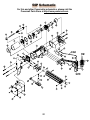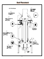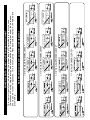
1
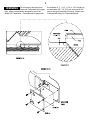
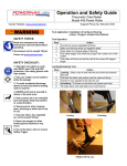
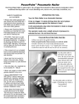
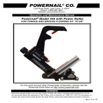
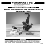
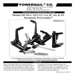
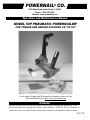
1300 Rose Road, Lake Zurich, IL 60047
phone: 1-800-323-1653
website: www.powernail.com ®
POWERNAIL CO.
1300 Rose Road, Lake Zurich, IL 60047
Operation and
Maintenance
Manual
Phone:
1-800-323-1653
Website: www.powernail.com
MODEL 50P PNEUMATIC POWERNAILER ®
Operation and Maintenance Manual
For T&G Flooring 3/8" to 5/8"
REV. 1.0
MODEL 50P PNEUMATIC POWERNAILER®
FOR TONGUE AND GROOVE FLOORING 3/8” TO 5/8”
For this parts list and other Powernailer schematics, please visit the
Powernail Parts
W Store
A RatNhttp://www.powernail.com
ING
WARNING
Read
this you
manual
you use
this Nailer. Followdirectly
all safety
warnings and instructions.
If you
ad this manual
before
usebefore
this Nailer.
Follow
at 1-800-323-1653
for assistance
or contact
®
are
uncertain
about
the
operation
of
the
Nailer,
call
us
directly
at
1-800-323-1653
for
assistance
or retain this
safety warnings and instructions. If you are
the closest Powernail Dealer for help. Please
contact
the
closest
Powernail
Dealer
for
help.
Please
retain
this
information
for
future
reference.
certain about the operation of the Nailer, call us
information for future reference.
03.23.10
Revision 1.0 – 03.06
2
TO PREVENT ACCIDENTAL INJURIES:
Always wear approved front and side EYE PROTECTION
when operating this Nailer. Others in the work area
should also wear front and side EYE PROTECTION. Eye
protection will help guard against flying nails and debris,
which could cause severe eye injury.
EAR PROTECTION may be required to prevent hearing
damage when there are high noise levels in the work
area.
Always DISCONNECT THE AIR SUPPLY before making
any adjustments, repairing, clearing jams or when the
Nailer is not in use.
Never attach the female end of a quick disconnect to the
Nailer. This will trap air inside the Nailer and permit it to
be discharged. Only the unrestricted male connection
should be attached to the Nailer
Use only regulated compressed air, do not use bottled
gases of any kind to power this Nailer. Normal air
pressure should not exceed 110 psi or damage to the
Nailer and seals may occur. Excess air pressure can
cause the Nailer to explode.
THE TRIGGER IS A SAFETY DEVICE and should only
be pulled when the Nailer is in proper position on the
work surface and before the plunger is struck with the
mallet. Do not tie or tape down the safety trigger as the
Nailer could discharge if dropped on the plunger. The
Nailer will not fire unless the trigger is pulled before the
mallet blow.
Do not use the trigger safety as a lock up for the
plunger then rack the wood using the locked up Nailer
body. It will severely damage the mechanism and the
Nailer.
DO NOT USE THE METAL END OF THE MALLET TO
STRIKE THE PLUNGER, use the rubber capped end
only.
Never place any part of the body in the discharge
path of the Nailer when air is connected to the Nailer.
Always connect air hose to unloaded Nailer to prevent
any accidental discharge from occurring.
Never leave the Nailer unattended while it is connected
to an air supply.
DESCRIPTION
The Powernailer® Model 50P Pneumatic Nailer is the
latest model designed to bring Powernail quality to a
pneumatic nailer. For those looking for the ease of use of
a pneumatic tool, the Powernailer® Model 50P designed
for use with only 1" , 1-1/4", 1-1/2" and 1-3/4" (18 gage)
Powercleats® nails provides several distinct advantages.
The Model 50P can nail down 3/8", 1/2", 5/8" and
some exotic 3/4" tongue and groove hardwood flooring
through the use of easy to change, no mar pad and
shims. For a superior pneumatic Nailer, look to the
company that has been the industry’s quality leader for
over 50 years, POWERNAIL® COMPANY, INC.
OPERATION
Read these instructions carefully before you use the Nailer.
To use the Model 50P, simply place the nailer on the
floor, pull nailer back so locating ears catch the edge of
the floor above the tongue, pull the safety trigger and
tap the plunger with the rubber capped mallet end and
let the Nailer drive and set the nail at the correct 45
degree angle. Adjust nailer by adding shims between
the adapter foot and pad until there is a slight gap
between the tongue of the wood and the locating ears of
the adapter foot. See example 1B and 2A.
To Load Model 50P LS or SS
Place up to one stick (100) of Powercleats® (18 gage)
nails, 1" , 1-1/4" , 1-1/2" or 1-3/4" long into the nail
channel feed slot. Pull back the spring loaded nail
pusher over the nails until it contacts the last nail and
slowly release the nail pusher.
To Unload
To remove nails from the nail channel, pull the two
round knobs on the nail pusher together. This will clear
it from the nail path. Then turn the nailer over so the
nails slide out of the channel.
3
WARNING
Do not use any nails other than 3 are available in 1", 1-1/4", 1-1/2" or 1-3/4" lengths to
Powernail
Powercleats®
(18 gage) or accommodate
1/2", 5/8"3/8"
and
exoticand
3/4"
Do
not
use any nails
other than Powernail
1-3/4" lengths to 3/8",
accommodate
to some
5/8" tongue
WARNING:
nails, which are specifically
designed
fornails,
use which
in the are
®
®
tongue
and groove
hardwood
flooring.
Contact
your
Powercleats
(18 gage)
groove
hardwood
flooring.
Contact your
Powernailer
Model
50Pdesigned
Powernailer.
gage) nails dealer
®
Powernailer®
dealer
for Powercleats® nails.
specifically
for use Powercleats®
in the Model 50P(18
Powernailer.
for Powercleats
nails.
Powercleats® (18 gage) nails are available in 1", 1-1/4", 1-1/2"
4
WARNING Do not over lubricate the Nailer,
It is not necessary to hit the Nailer
excess oil mist or drops will be vented with spent air
hard to activate it. Never hit the Nailer with excessive
force or with the metal end of the mallet, this will damage when over lubricated. Excess oil could stain the wood
flooring, walls or furnishings. Dry fire the Nailer, without
the Nailer.
nails, to purge excess oil, before you begin to nail down
Never use the Safety Trigger interlock to lock up the
flooring. We will not be responsible for oil stains.
plunger and rack the wood with blows to the Nailer
Before storing the Nailer, lubricate and cycle the Nailer in
body. This will severely damage the safety mechanism
insure internal parts are oil protected from corrosion.
and Nailer. This abuse and damage is not covered by the
PARTS & SERVICE:
warranty.
When ordering parts include the part number, part
Before each use check all screws to be sure they are tight.
description, Powernailer model and serial number. Be sure
Shock and vibration can loosen screws. Do not over
to state the quantity of the part(s) required. Contact your
tighten any screw.
Powernail Dealer for the necessary parts or service.
AIR SUPPLY:
WARNING Never work on the Nailer if the air
The air must be clean and dry. Dirty and/or wet air
line is attached. Always disconnect the air line from the
will damage the Nailer. A combination filter-regulatorlubricator is required for proper Nailer performance and Nailer first.
should be placed close to the Nailer per manufacturer’s
NAILER DISASSEMBLY:
recommendations.
TO REPLACE RUBBER BUMPER (#31):
Fill the lubricator with Mobile DTE Light Synthetic
1. Disconnect the air supply
Hydrocarbon Oil. Adjust the lubricator to the
2. Remove the four (4) cap screws holding the Adapter
manufacturers’ recommendations. Do not over oil the
Nailer, as excess oil will be discharged with the spent air Foot, Foot and Nail Channel assembly to the main Body
(see illustration).
and could stain the wood flooring, walls or furnishings.
We will not be responsible for oil stains.
3. Pull the Rubber Bumper out of the cylinder bore.
WARNING Detergent oil is not recommended Replace the old Bumper if it shows signs of wear or it is
split.
and may damage the seals. Consult the filter regulator
4. Reverse these steps to reassemble the Nailer. Be sure to
lubricator manufacturer’s recommendations for proper
align the Driving Blade with the slot in the Nail Channel
operation, settings and unit maintenance.
Assembly while you reassemble the Nailer. NEVER FIRE
The air source must continuously deliver 70 to 110 psi
THE NAILER WITHOUT THE RUBBER BUMPER
and
INSTALLED, IT WILL DAMAGE THE NAILER.
3-1/2 cubic feet of air per minute to operate the Nailer.
TO REPLACE DRIVING BLADE(#17):
Connect a clean air hose and air regulator to the Nailer.
1. Disconnect the air supply
Check for air supply leaks that waste air and starve the
2. Remove the four socket head cap screws holding the
Nailer of air thereby reducing its performance.
Adapter Foot, Foot and Nail Channel Assembly to the
LUBRICATION:
body.
If you do not use an in line lubricator, you must lubricate
3. Remove the Rubber Bumper
the Nailer manually. The frequency of lubrication is
dependent upon the duty cycle of the Nailer. Continuous 4. Pull the Driving Blade with pliers until the Piston
duty requires more frequent oiling than intermittent duty. is fully extended outward towards the bottom of the
At least every eight (8) hours place two to four drops of cylinder.
WARNING
Mobile DTE Light Oil, supplied with your Nailer, into
the disconnected air line male connector attached to the
Nailer.
5. Use the 15/16" box wrench supplied to unscrew the
Driving Blade Jam Nut and remove it. Hold the Piston
5
from turning while unscrewing the Jam Nut by holding
the piston hex with the 1-1/8" box wrench supplied.
6. Push out the 1/4" diameter blade retaining Dowel Pin
and remove the broken Driving Blade stub.
7. Install a new Driving Blade in the slot and replace the
Dowel Pin. Screw on the retaining Jam Nut using the
same tools. If the Jam Nut becomes worn and loose after
frequent removals, it should be replaced.
4. Push Safety Yoke (#26) aside and unscrew the three
10-32 cap screws holding the Plunger (#13) to the
Return Cylinder (#12).
5. Pull the Plunger up and out of the Nailer Body (#1)
cavity.
6. Remove the Return Cylinder 0 Ring Gasket (#34)
located on the top of the Return Cylinder under the
Plunger.
8. Check the fit, there should be some sideways
movement between the Driving Blade and the Jam Nut
assembly. This is desirable and helps the blade to align
itself with the mating parts.
7. Turn the Nailer over and remove the four cap
screws (#48), that fasten the Adapter Foot and Nail
Channel Assembly to the Nailer Body and lift the
Assembly off the Body.
9. Reassemble the components. Be sure to align
the Driving Blade with the slot in the Adapter Foot
Assembly, it goes in only one way.
8. Remove the Rubber Bumper (#31).
SEAL REPLACEMENT:
There are 7 seals that may require replacement. We
recommend that you have your POWERNAIL Dealer
replace the Seals.
10. Hold the Piston Rod (#10) with an 11/16" socket
over its hex end opposite the Piston. Do not use pliers
or a vise anywhere on the metal parts, they can
damage the sealing surfaces.
SEAL KIT:
You may choose to buy a Seal Replacement Kit and
replace the seals yourself. It is good practice to replace
all seals at one time regardless if only one seal needs
replacement.
SEAL DESCRIPTION & NUMBER:
1. Piston U cup Lip Seal (#19)
2. Return Cylinder U cup Lip Seal (#20)
3. Piston Rod U cup Lip Seal (#21)
4. Rubber Seat (#30)
5. Plunger Seal Set (#32)
6. Plunger Wiper Seal (#33)
7. Return Cylinder 0 Ring Gasket (#34)
To change Seals follow these procedures. Be sure the air
line is disconnected from the Nailer first before making
any repairs. Consult the illustration for the name and
location of the following component parts.
DRIVING BLADE ASSEMBLY REMOVAL:
1. Disconnect the air supply.
2. Remove Rubber Plunger Cap (#18).
3. Unscrew & remove Body Cap (#2).
9. Pull the Driving Blade Assembly out of the Nailer
Body by pulling on the Driving Blade.
11. Use the supplied box wrenches to remove the
5/8"-18 Jam Nut (#49). Remove the Dowel Pin (#42)
and Driving Blade (#17).
12. Unscrew the Piston from the Piston Rod using the
supplied box wrenches and separate the Piston, Piston
Rod and Return Cylinder.
For Step-by-Step
Videos and
Instructions,
Visit our Web Site
at
www.Powernail.com
TO REPLACE THE SEALS:
Plunger Seal Set (#32):
1. Remove the Teflon® Seal and its O-ring expander
from the Plunger groove using a bent paper clip or pick.
Be sure not to scratch the inside walls of the seal groove
with the wire hook.
2. Clean out the seal groove. Place a new O-ring into
the seal groove by stretching it over the Plunger body.
Make sure the O-ring is not twisted in the groove. Place
a new Teflon® Seal Ring into the seal groove over the
O-ring.
3. Carefully push the Teflon® Seal Ring over the edge
of the Plunger with your thumbs and into the groove.
Do this as quickly as possible to reduce stretching of
the Teflon® Seal Ring. DO NOT OVER STRETCH
THE TEFLON® SEAL RING. Be sure the Teflon®
Seal Ring is centered all around the seal groove and not
twisted.
4. Wipe off the Seal surface with a clean rag and
lubricate it generously with the supplied Mobile DTE
Light Air Tool Oil lubricant.
Seal into the groove. Make sure the lip seal is not
twisted in the groove and the lips face the top of the
Nailer. See the sketch on next page (#19).
3. Carefully wipe off the U Cup Lip Seal surface
with a clean rag and lubricate it generously with the
supplied Mobile DTE Light Air Tool Oil lubricant.
Return Cylinder U Cup Lip Seal (#20):
1. Use a bent paper clip or pick to remove the old
U Cup Lip Seal from the internal seal groove inside
the Return Cylinder. Be careful not to scratch the
inside walls of the seal groove with the wire hook.
2. Clean out the seal groove. Place a new U Cup
Lip Seal into the groove, be sure it is not twisted in
the groove. Be sure the lips are facing the inside of
the Return Cylinder as shown in the sketch on next
page.
WARNING
The U-Cup Lip Seals #20 and
#21 look alike, but they are different, DO NOT mix
them up.
3. Carefully wipe off the Lip Seal surface with
a clean rag and lubricate it generously with the
supplied Mobile DTE Light Air Tool Oil lubricant.
Rubber Seat (#30):
1. Remove the Cylinder Sleeve (#14). The Cylinder
Sleeve would slide out of the Nailer Body when you
pull out the Driving Blade
Piston Rod U-Cup Lip Seal (#21):
1. Remove the old U-Cup Lip Seal from the seal
groove with a bent paper clip or pick using care not
to scratch the inside walls of the seal groove with
the wire hook.
2. Remove the metal Support Ring (#29) and Rubber
Seat from inside the Nailer body. NOTE THAT THE
CHAMFER ON THE INSIDE OF THE RUBBER
SEAT FACES THE BOTTOM OF THE NAILER.
Do not reverse the direction of the chamfer when you
replace the Rubber Seat.
3. Replace the Rubber Seat, Support Ring and Cylinder
Sleeve. Be sure to re install the steel Cylinder Sleeve
with the chamfered inside edge facing the BOTTOM of
the Nailer.
Piston U Cup Lip Seal (#19):
1. Remove the old Piston U Cup Lip Seal from the
Piston using a bent paper clip or pick, being careful not
to scratch the inside walls of the seal groove or the edge
of the Piston with the wire hook.
2. Clean out the seal groove. Place a new U-Cup Lip
6
2. Clean out the seal groove and install a new UCup Lip Seal. Be sure the Lips are facing the right
direction and are not twisted in the groove. See the
sketch on next page.
Plunger Wiper Seal (#33):
1. Use a bent paper clip to pick out the felt Wiper
Seal out of its groove in the Body Cap (#2).
2. Clean out the groove and insert a new felt Wiper
Seal. Saturate the new felt Wiper Seal with oil.
Return Cylinder O-Ring Gasket (#34):
1. Place a new O-Ring Gasket in the groove
on top of the Return Cylinder when you
reassemble the Driving Blade Assembly.
2. Wipe off the O-Ring Gasket seal surface
and lubricate it generously with the supplied
Mobile DTE Light Air Tool Oil lubricant.
REASSEMBLING THE NAILER:
1. Be sure the Rubber Seat, Support Ring and
Cylinder are installed in the Body and are
facing the correct direction.
2. All seal surfaces must be clean and
lubricated generously with the supplied Mobile
DTE Light Air Tool Oil lubricant.
Replace any part that shows signs of wear.
3. Use care when installing the seals into
their respective cavities. Be sure the Seals are
contained in their groove and do not come out
as the parts slide together. Generous cavity
lead in chamfers have been provided to help
Seal installation.
11. Install the Body Cap and Plunger Rubber Cap.
12. Turn the Nailer upside down. Install the Rubber
Bumper, Nail Channel Assembly and Adapter Foot. Be
sure to align up the Driving Blade with the slot in the Foot
before the Nailer is closed up.
13. NEVER FIRE THE NAILER WITHOUT THE
RUBBER BUMPER INSTALLED, IT WILL DAMAGE
THE NAILER BEYOND REPAIR.
TO CLEAR A NAIL JAM:
1. It helps to tap the Driving Blade back to the retracted
position before trying to remove a jammed nail. A spare
Driving Blade works best for this.
2. Try to pull the jammed nail out of the gate with a pair
of long nose pliers. If this does not work remove the four
(4) cap screws holding the Foot, Gate and Nail Channel
Assembly together.
3. Separate the Foot and Gate with a screw driver just
enough to clear out the jammed nail.
4. Put thread locking compound on all screws and
reassemble the components.
4. Carefully insert the Piston Rod into the
Return Cylinder and screw the Piston onto the
rod. Be sure the Piston is facing the correct
way, ears up, hex down.
For Step-by-Step
Videos and
Instructions,
5. Assemble the Driving Blade, Dowel Pin and
Jam Nut on to the Piston Rod.
6. Insert the Driving Blade Assembly up into
the bottom of the Nailer Body Cylinder.
7. Be sure there is a new O-Ring Gasket in the
top groove of the Return Cylinder.
Visit our Web Site
at
www.Powernail.com
8. Insert the Plunger into the top cavity of the
Body. Line up the holes and install the three
Plunger retaining screws. It is important that
the three #10-32 screws are tight or air leakage
will occur.
9. Install the Body Plate.
10. Position the Safety Yoke into the Plunger
Groove.
7
50P Parts List
For this parts list and other Powernailer schematics, please visit the
Powernail Parts Store at http://www.powernail.com
ITEM #
PART NO.
DESCRIPTION
Qty Req’d
Key Ref.
Assy/Kit
1
09-50P-3001
Body
1
F
2
09-50P-3002
Cap
1
S
3
09-445-29815
Handle - Extra Long
1
S/A
A-5
4
09-445-29703
Handle - Long
1
S/A
A-2
5
09-445-29703.1
Handle - Short
1
S/A
A-3
6
09-445-29704
Handle Half Cover
1
S/A
A-2,A-3,A-5
7
09-50P-3005
Adapter Foot
1
S
8
09-50P-3006
Foot
1
S/A
A-4
9
09-50P-3008
Channel
1
S/A
A-4
9B
09-50P-3009
Channel - Long
1
S/A
A-6
10
09-50P-3010
Piston Rod
1
S/A
A-6
11
09-200-3011
Piston
1
S/A
A-6
12
09-200-3013
Return Cylinder
1
S/A
A-6
13
09-200-3014
Plunger
1
S/A
A-6
14
09-200-3015
Cylinder Sleeve
1
S
15
09-50P-3042
Gate (Replaces 09-50P-3016)
1
S/A
A-4
16
09-50P-3017
Gate Plate
1
S/A
A-4
17
09-50P-3018
Driving Blade
1
S/A
A-6
18
09-200-3022
Rubber Cap
1
S
19
09-200-3026
Piston U-cup Lip Seal
1
K/S/A
A-1,A-6
20
09-200-3027
Return Cylinder U-cup Lip Seal
1
K/S/A
A-1,A-6
21
09-200-3028
Piston Rod U-cup Lip Seal
1
K/S/A
A-1,A-6
22
09-200-3034
Nail Pusher Spring
1
S/A
A-4,A-9
23
09-200-3035
Spool
2
S/A
A-4,A-9
24
09-445-29832
#10-32 X 3/4 SHCS (Plunger)
3
S/A
A-6
25
09-200-3057
#10-32 X 1/2 FHCS Slotted (Pad)
4
S
26
09-445-29707
Safety Yoke
1
S
27
09-2003019
Body Plate (.035 Thick)
1
S
28
09-445-29720
Trigger
1
S/A
29
09-445-29721
Support Ring
1
S
30
09-445-29723
Rubber Seat
1
K/S/A
31
09-445-29724
Rubber Bumper
1
S
32
09-445-29725
Plunger Seal Set
1
K/S/A
A-1,A-6
33
09-445-29729
Plunger Wiper Seal
1
K/S/A
A-1,A-6
34
09-445-29731
Return Cylinder O-ring Gasket
1
K/S/A
A-1,A-6
35
09-445-29816
Trigger Cable - Extra Long
1
S/A
A-5
36
09-445-29732
Trigger Cable - Long
1
S/A
A-2
37
09-445-29732.1
Trigger Cable - Short
1
S/A
A-3
A-2,A-3,A-5
A-1,A-6
KEY: S=Sold Separately, A= Sold as part of assembly, F=Factory replacement only, K=Sold as part of a Kit
9
(Model 50P Parts List, continued)
ITEM #
PART NO.
38
09-445-29733
39
40
41
42
43
44
45
46
47
48
49
50
51
52
53
54
55
56
57
58
59
60
61
62
09-445-29735
09-445-29735.2
09-445-29739
09-445-29740
09-445-29741
09-445-29742
09-445-29743
09-445-29744
09-445-29745
09-445-29747
09-445-29748
09-445-29750
09-445-29751
09-445-29754
09-445-29756
09-445-29758
09-445-29759
09-445-29760
09-445-29822
09-50P-3037
09-50P-3038
09-50P-3040
09-50P-3041
09-50P-3036
QTY REQ’D
Key/Ref
Safety Yoke Springs
DESCRIPTION
2
S
Nail Pusher
Nail Pusher Knob
1/4 X 3/4 Dowel Pin (Trigger)
1/4 X 1/2 Dowel Pin (Driving Blade)
1/8 X 5/8 Roll Pin (Gate)
1/4-20 X 7/8 SHCS (Xl - Handle Half)
1/4-20 X 1 SHCS (Cap)
1/4-20 X 3/4 SHCS (Handle)
#10-32 X 1-1/4 SHCS (Knob)
1/4-20 X 1-1/4 SHCS W/patch (Foot)
5/8-18 Jam Nut (Driving Blade)
#8-32 X 1-1/2 FHCS (Spacer)
#8-32 Locknut (Spacer)
#10-32 X 1/2 SHCS (Foot)
1/4 X 1 Spacer (Channel)
1/4 Split Ring Lock Washer (Foot)
3/8 NPT 45 Degree Street Elbow
#8-32 X 1/4 BHCS (Cable)
#10-32 X 3/4 SHCS w/patch (Gate)
.200 Thick UHMW Plastic Pad
Shim
Channel Plate
#6-32 X 3/8 BHCS (Channel Plate)
.150 Thick Plastic Pad
1
1
1
1
2
1
4
6
1
4
1
2
2
4
2
4
1
1
3
1
4
1
2
1
S/A
S/A
S/A
S/A
S/A
S
S
S/A
S/A
S
S/A
S/A
S/A
S/A
S/A
S
S
S
S/A
S
S
S/A
S/A
S
Assy/Kit
A-4,A-9
A-4,A-9
A-2,A-3,A-5
A-6
A-4
A-2,A-3,A-5
A-4,A-9
A-6
A-4
A-4
A-4
A-4
A-4
A-4
A-4
Model 50P Assemblies, Kits and Accessories
ITEM
A-1
A-2
A-3
A-4
.
A-5
A-6
A-7
A-8
A-9
A-10
A-11
A-12
A-13
A-14
PART NO.
09-200-3058A
09-445-29759A
09-445-29760A
09-50P-3065A
09-50P-3062A
09-445-29824A
09-50P-3064A
09-AW-445
09-445-29757A
09-200-3063A
09-445-29765
09-445-29766
09-445-29768
09-445-5421
09-445-5421R
DESCRIPTION
Seal Kit (1 Each Of All Seals)
Long Handle Assembly
Short Handle Assembly
Nail Channel Assembly (Standard)
Discontinued: Use Asm 09-50P-3065A
Extra Long Handle Assembly
Driving Blade Assembly w/Rubber Seat
Allen Wrench Set
6 Oz. Bottle Mobile Dte Light Oil
Nail Pusher Assembly
3/8” X 50 Ft. Vinyl Hose with Fittings
3/8” M & F Coupling Set
Box Wrench (2)
Air Gauge
Filter/Regulator Gauge
QTY
1
1
1
1
1
1
1
1
1
1
1
1
2
1
1
KEY
S
S
S
S
S
S
S
S
S
S
S
S
S
S
S
KEY: S=Sold Separately, A= Sold as part of assembly, F=Factory replacement only, K=Sold as part of a Kit
11
50P Schematic
POWERNAILER
MODEL 50P
For this and other Powernailer schematics, please visit the
Powernail Parts Store at http://www.powernail.com
62
10
7
Seal Placement
#34
#33
#21
#32
#20
#30
#19
11
15/32”
1” 18 GAGE POWERCLEATS®
1-1/4” 18 GAGE POWERCLEATS®
1-1/2” 18 GAGE POWERCLEATS®
1-3/4” 18 GAGE POWERCLEATS®
Nail Penetration for 3/4" and 5/8" Underlayment
5/8”
13/16”
This chart will assist you in determining the proper length of Powercleats to use for various
thicknesses of flooring. Approximate vertical penetration of the Powercleat under the hardwood
floor is shown for each application. This is only a guide. Results should be tested in the field before
proceeding.
POWERCLEATS LENGTH DETERMINATION CHART
POWERNAILER MODEL 50P TROUBLE SHOOTING CHART
PROBLEM
POSSIBLE CAUSE
SOLUTION
Check air supply for 70 psi minimum to 110 psi
maximum
2.
Lack
of
lubrication
Manually lubricate through male air inlet fitting
Driving blade
3. Excessive dirt inside nailer
Disassemble and clean
does not
retract
4. Bent or burred driving blade
Replace driving blade
5. Seals worn out
Replace all seals
6. U-Cup Lip Seals installed upside down
Replace all seals
1. Low air pressure
Turn up air pressure to 70-110 psi max
2. Bent or burred driving blade
Replace driving blade
Driving blade
3. Air supply restricted by small orifice
Use 1/4" minimum diameter air fittings
retracts slowly
4. U-Cup Lip Seals installed upside down
Replace all seals
5. Excessive dirt inside nailer
Disassemble, clean and lubricate
1. Low air pressure
Turn up air pressure to 70-110 psi max
2. Broken Driving Blade
Replace Driving Blade
3. Nail hit hard surface
Move from obstruction
Nail is not
countersunk 4. Piston U-Cup Lip Seal installed upside down Replace all seals
5. Driving blade jam nut came loose
Retighten or replace jam nut
6. Worn out gate
Replace gate.
1. Air supply fittings loose
Tighten all air line fitting connections
1. Zero or Low air pressure
1
2
3
Check air supply for 110 psi maximum—
replace all seals
2. Excess air pressure blew out seals
4
5
6
7
Nailer leaks air 3. Plunger screws loose
4. Cracked or damaged body
5. Seals worn out
6. Seals need to be seated
Bottom of
1. Operated without rubber bumper installed
nailer cracked
2. Excessive air pressure used
off
1. Not using 18 gage Powercleats nails
2. Continued use after a short hit
3. Nail pusher damaged or spring broken
Nails jam in
4. Nail channel lose
nailer
5. Bent nail stuck in nail guide
6. Hit another set nail or hard object
7. Nail gate worn out
Tighten 3 plunger screws
Replace body
Replace all seals
Dry fire Nailer
Replace damaged parts
Replace damaged parts
Use 18 gage Powercleats nails only
Clear nail immediately after short hit
Replace nail pusher assembly
Tighten nail channel retaining screws
Disassemble and clear out bent nail
Move from obstruction
Replace nail gate
Replace damaged plunger, safety yoke and
plunger seal
Plunger locked 1. Safety trigger not being depressed
up—won't
move or fire 2. Lack of lubrication
Manually lubricate through male air inlet fitting
13