Transcript
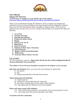
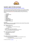
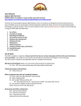
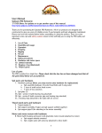
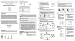
PACKAGE CONTENTS
Item #000-000
Installation
1
NOTE: Parts not shown to actual size.
Model #99110
USE AND CARE GUIDE
E
F
UNIVERSAL CEILING FAN REMOTE CONTROL
Installation
2
Turning off the power
□□ Before installation, use the pull chains to
set the fan speed to HIGH and the light
to ON.
□□ Ensure the power is OFF at the outlet box
and wall switch location before proceeding
with installation.
CR 2032
A
Part
Warranty
C
B
Description
D
G
A
Receiver
1
Remote Control
1
C
Remote Control Mount
1
D
Wire Connectors
4
E
Long Fasteners
2
F
Short Fasteners
2
G
Battery
1
1-YEAR LIMITED WARRANTY
WHAT IS COVERED
The manufacturer makes the following limited warranty to the original purchaser of the remote
control: Your remote control is warranted to be free from defects in material and workmanship for
a period of one year from the date of sale. If the remote control malfunctions or fails within the
warranty period due to a defect in material or workmanship we will replace it free of charge. If
the original purchaser ceases to own the remote control, this warranty and any implied warranty,
including but not limited to any implied warranty of merchantability or fitness for a particular
purpose, are voided. This warranty is in lieu of all other express warranties. The duration of any
implied warranty, including, but not limited to, any implied warranty of merchantability or fitness
for a particular purpose, in respect to any control, is expressly limited to the period of the express
warranty set forth above for such control.
WHAT IS NOT COVERED
This warranty excludes malfunctions or failures which were caused by repairs by persons not
authorized by us, mishandling, improper installation, modifications, or damage to the remote
control while in your possession, or unreasonable use. This warranty does not apply to batteries or
to deterioration or damage to the product caused by the use of faulty batteries. In no event shall
the manufacturer be liable for consequential or incidental damages. Some states do not allow
limitations on how long an implied warranty lasts or the exclusion or limitations of incidental or
consequential damages, so the above limitations or exclusions may not apply to you. This warranty
gives you specific legal rights and you may also have other rights which vary from state to state.
Questions, problems, missing parts? Before returning to the store,
call Customer Service
9 a.m.-5:30 p.m., EST, Monday-Friday
1-888-830-1326
WWW.HOMEDEPOT.COM
Care and Cleaning
To clean, use soft brushes or cloths to prevent scratching. Cleaning products may damage
finishes.
Pre-Installation
TOOLS REQUIRED
CAUTION: To avoid possible electrical shock, before installing or servicing your fan, disconnect the power
by turning off the circuit breakers to the outlet box and associated wall switch location. If you cannot lock the
circuit breakers in the off position, securely fasten a prominent warning device, such as a tag, to the service
panel.
Pliers
Flat Blade
Screwdriver
Phillips
Screwdriver
□□ Using the orange wire connectors (D), connect the black wire (ungrounded) from the ceiling
to the black wire from the receiver (A). Connect the white wire (grounded) from the ceiling to
both the white wire from the receiver (A) and the white wire from the fan.
□□ After all wires are connected and secured with wire connectors (D), re-install the canopy.
□□ Remove the canopy by following
the instructions supplied by the fan
manufacturer.
D
RECEIV
OM
ER
FR
black
white
A
OFF
M FAN
FRO
6
Installing the receiver
□□ Choose the hanging system that most closely resembles the one used by your fan, and install
the receiver (A) and wire as directed.
□□ You may have installation issues if the fan is installed on an angled ceiling.
NOTE: Some fans may have considerable excess lead wire. For easier receiver (A)
installation, cut the excess wire, leaving a minimum of 8 in. remaining. Re-strip the fan lead
wires 1/2 in., and place the remaining excess wire into the ceiling electrical box. The bracket
and fan must remain properly grounded.
CAUTION: All wiring must be in accordance with national and local electrical codes. ANSI/NFPA 70. If you
are unfamiliar with wiring, use a qualified electrician.
white (grounded)
7
Installing the battery
□□ To access the battery compartment,
remove the small Phillips head screw that
secures the battery door to the remote
control (B).
□□ Replace the used battery with a CR2032
battery (G) when necessary. The battery
should be installed with the positive (+)
side up.
□□ Turn on the power at the outlet box and
wall switch location.
□□ Within three minutes of restoring power to
the fan, press both the Fan Off button and
the High button for at least four seconds.
The remote control (B) is now paired to the
fan’s receiver (A).
NOTE: If using the remote with multiple fans,
repeat this process for each fan.
Cable Tie
Receiver
Receiver
NOTE: This device complies with part 15 of the FCC Rules. Operation is subject to the following two
conditions: (1) this device may not cause harmful interference, and (2) this device must accept any
interference received, including interference that may cause undesired operation.
OR
B
Ceiling
Bracket
Ceiling
Plate
OR
Receiver
OR
A
Battery
Door
Fan Body
Canopy
Canopy
Phillips
Head
Screw
Canopy
Problem
Solution
Install a fresh battery. Make sure the battery is installed
correctly.
The CFL bulbs flicker.
Turn the light switch off and back on. Within three
minutes, hold down the Fan Off button while pressing the
Light button twice. If the problem is not corrected, repeat
the process up to three times.
Fan Off
B
Operation
4
Wiring the receiver to the fan
□□ Using the orange wire connectors (D), connect the yellow wire from the receiver (A) to the
black wire from the fan. Connect the blue wire from the receiver (A) to the blue wire (or
possibly black with white stripe wire) from the fan.
NOTE: If you are uncertain about wire colors or connections, please contact a qualified
electrician.
Troubleshooting
The fan remote control operates
inconsistently.
Pairing the remote control and receiver
NOTE: The remote control must be paired
before the fan will operate.
NOTE: This product conforms to UL Standard 507.
NOTE: This equipment has been tested and found to comply with the limits for a Class B digital device,
pursuant to Part 15 of the FCC Rules. These limits are designed to provide reasonable protection against
harmful interference in a residential installation. This equipment generates, uses and can radiate radio
frequency energy and, if not installed and used in accordance with the instructions, may cause harmful
interference to radio communications. However there is no guarantee that interference will not occur in a
particular installation. If this equipment does cause harmful interference to radio or television reception,
which can be determined by turning the equipment off and on, the user is encouraged to try to correct
the interference by one or more of the following measures: Reorient or relocate the receiving antenna,
increase the separation between the equipment and receiver, connect the equipment into an outlet on a
circuit different from that to which the receiver is connected. Consult the dealer or an experienced radio/TV
technician for help. Any changes or modifications to the remote control or receiver not expressly approved by
the manufacturer may void one’s authority to operate this remote control.
OM CEILING
FR
black (ungrounded)
white
3
Safety Information
The remote control only works when
held at close range.
Ladder
er
ow
rn P
Tu
NOTE: If you are uncertain about
wire colors or connections, please
contact a qualified electrician.
Wiring the receiver and fan to the ceiling
□□ Remove the wire connectors that
connect the wires from the outlet box
to the fan, leaving the grounding wires
connected.
Quantity
B
5
Removing the canopy
D
RECEIV
OM
ER
FR
blue
yellow
A
M FAN
FRO
blue
1
Using the remote control
□□ Press one of the fan speed buttons
(located under the Fan Off button) to turn
the fan on. Press the Fan Off button to turn
the fan off.
High
ooo
Medium
oo
o
Low
□□ Quickly press the Light button to turn the
lights off and on. Hold the Light button to
raise and dim the light level.
□□ Your remote control comes with a wall
mount (C) that has two posts to mount
your remote control (B) when not in use.
black
Light
Fan
Off
High
Install a fresh battery.
Medium
B
Low
B
C
Post
2
High
Using the Safe Exit program
NOTE: The Safe Exit program gives you about
thirty seconds of light, when you turn the lights
off, to exit the room before the lights go out.
□□ Hold the Fan Off button for at least three
seconds to initiate the Safe Exit program.
The lights will stay on 50% brightness for
15 seconds and then begin to dim. After
a total of 30 seconds, the lights will be
completely off.
NOTE: For CFL lighting, the lights will stay on
100% brightness for 30 seconds. After a total of
30 seconds, the lights will be completely off.