1
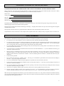
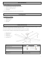
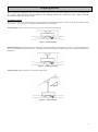
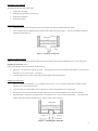
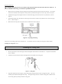
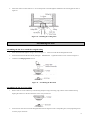
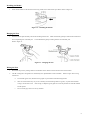
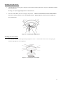
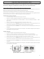
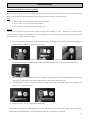
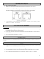
CEILING FAN MANUAL INSTALLATION OPERATION MAINTENANCE WARRANTY INFORMATION INFINITE BREEZE® CORDOVA / FIONA DIRECT CURRENT CEILING FAN CORDOVA MODEL # HB54BN-LK FIONA MODEL # HB54WH-LK CAUTION READ INSTRUCTIONS CAREFULLY FOR SAFE INSTALLATION AND FAN OPERATION. HB54 – V6.0 CONGRATULATIONS ON YOUR PURCHASE. CONGRATULATIONS ON PURCHASING THE LATEST IN ENERGY SAVING CEILING FANS! We are proud of our work and we appreciate the opportunity to supply you with the best ceiling fan available anywhere in the world. Before installing your fan, record the following information for your records and warranty assistance. Model Name: Catalog / Model No.: Serial No.: Date Purchased: Where Purchased: This Infinite Breeze ceiling fan runs on DC (Direct Current) power which gives it the benefit of being super energy efficient, while still maintaining high volume air-movement and silent operation. Energy Savings: The DC motor is the latest technology in fan design. Its highly efficient motor saves up to 65% more energy than ceiling fans with traditional AC motors. Silent operation: This DC fan motor is programmed with a stabilized current which efficiently reduces motor noise. 6-Speed Remote Control: This DC Fan comes complete with a 6-Speed remote control, which provides you a greater choice of comfort levels. Safety Precautions The information contained herein has been prepared to ensure you of trouble-free operation of your Ceiling Fan. 1. To ensure the success of the installation, be sure to read the instructions and study the diagrams thoroughly. 2. To reduce the risk of personal injury, attach the fan directly to the support structure of the building according to these instructions, and use only the hardware supplied. Note that the structure must be able to support a weight of at least 65lbs. If you are mounting the fan to a ceiling junction box, the box must be able to support the moving weight of the fan. 3. To avoid possible electrical shock, before installing your fan, disconnect the power by turning off the circuit breakers to the outlet box and associated wall switch location. 4. All wiring must be in accordance with national and local electrical codes and ANSI/NFPA 70. should use a qualified electrician. 5. Make sure that your installation location will not allow the rotating fan blades to come into contact with any object, and that there is a minimum clearance of 12 inches from the blade tip to the wall or nearest object, and ensure the blades are mounted at a minimum height of 7 feet from the floor when the fan is installed. Please note that the greater this clearance is, the better the airflow from your fan will be. 6. The fan must be grounded. 7. Do not connect the fan motor to a dimmer switch. the motor. Only use the supplied fan controller. 8. It is not recommended that ceiling fans and gas appliances be operated in the same room at the same time. 9. The fan must be turned off and stopped completely before reversing the fan direction. the unit or controller (if installed). 10. Do not insert anything into the fan blades while the fan is operating, as this may cause personal injury, damage the blades, and upset the balance of the unit, causing it to wobble. 11. After the fan is completely installed, make sure that all connections are securely tightened to prevent any noise. 12. Because of the fan’s natural movement, some connections may loosen. It is recommended that you check the support connections, brackets, and blade attachments once a year to make sure they are all secured. If they are loose, tighten with a screwdriver. If you are unfamiliar with wiring, you This may give an unsatisfactory performance (motor hum) and cause damage to This will prevent any damage to the motor of Note: The important safeguards and instructions given in this manual are not meant to cover all possible conditions and situations that may occur. It must be understood that common sense, caution, and care are factors, which cannot be built into any product. The persons caring for and using the unit must supply these factors. 2 Before Installation To install a ceiling fan, be sure you can do the following: • Locate the ceiling joist or other suitable support in the ceiling • Drill holes for and install wood screws • Identify and connect electrical wires • Lift 40 pounds If you need help installing the fan, please contact a local licensed electrician. Tools Required Tools Required (Not Included): • Phillips Head Screwdriver • Standard Screwdriver • Wrench or Pliers • Step Ladder Check your Fan Parts Carefully unpack your ceiling fan to avoid damage to the fan parts. Check for any shipping damage to the motor or fan blades. the fan blades was damaged in shipment, return all the blades for replacement. If one of Note: If you are installing more than one fan, keep the fan blades in sets as they were in shipping. If any parts are missing or damaged, contact Infinite Breeze Parts Department at 1-844-245-3267 1. Motor housing (1pc) 2. Fan blades (5 pcs) 3. Canopy (1 pc) 4. Fan light housing (1 pc) 5. Glass shade (1 pc) Instructions for installation and use Screw package Mounting bracket (1 pc) Box screws x2 Woody screws x2 Motor housing (1 pc) Flat washers x2 Paper washer x 16 Fan blades (5 pcs) Blade screws x 16 Wire connectors v x3 Fan light housing (1 pc) Transmitter for remote control Glass shade (1 pc) Receiver for remote control 3 Preparing the Site These guidelines are designed to help you select the best location for your fan and to prepare the site prior to installing the fan. Proper ceiling fan location and attachment to the building structure are essential for safety, reliable operation, maximum efficiency, and energy savings. Installation Options: There are 3 optional positions for mounting your ceiling fan and this manual includes specific instructions for the fan mounting method of your choice. For a ceiling 8 feet or higher, standard mounting is recommended. Flush Mounting (Figure 1) fits closely to the ceiling, for low ceilings less than 8 feet high. Figure 1 – Flush mounting Standard Mounting (Figure 2) hangs from the ceiling on a downrod (included), for ceilings 8 feet or higher. For ceilings higher than 8 feet, you can purchase an extension downrod. All Infinite Breeze fans use sturdy 3/4” diameter pipe to assure stability and wobble-free performance. Figure 2 – Standard mounting Angle Mounting (Figure 3) hangs from a vaulted or angled ceiling Figure 3 – Angle mounting 4 Choosing the Fan Site: Within the room where you want to install the fan, choose a fan site where: • No object can come in contact with the rotating fan blades during normal operation. • Fan blades are at least 7 feet above the floor and the ceiling is at least 8 feet high. • Fan blades have no obstructions to air-flow, such as walls or posts, within 30 inches of the fan blade tips. • The fan is directly below a joist or support brace that will hold the outlet box and the full weight of the fan. See Figure 4 for minimum mounting distances. Figure 4 – Minimum mounting distances Using an Existing Fan Site: If you are preparing a new fan site, go to the preparing a new fan site section. If you plan to use an existing fan site, complete the following checklist for the support brace, ceiling hole, outlet box and wiring. If you cannot check off every item, see the preparing a new fan site section for instructions on properly preparing the site for your new fan. Fan Support System: • Fan must attach directly to building structure. • Fan support system must hold full weight of fan and light kit. Ceiling Hole: • Outlet box clearance hole directly below the joist or support brace Outlet Box: • UL-approved octagonal 4” x 1-1/2” outlet box (or as specified by the support brace manufacturer). • Outlet box secured to joist or support brace by wood screws and washers through inner holes of outlet box. • Outer holes of outlet box aligned with joist or support brace. • Bottom of outlet box recessed a minimum of 1/16” into ceiling. Wiring: • Electical cable secured to outlet box by approved connector. • Six inches of lead wires extend from outlet box. See figure 5 below for an adequate existing fan site. If your existing fan site is suitable, go to the Installing the Ceiling Plate section and begin installing your new Infinite Breeze fan. Figure 5 – Adequate exiting fan site 5 Preparing a New Fan Site To prepare the fan site follow four steps: • Cutting the Ceiling Hole • Installing the Support Brace (if necessary) • Installing the Outlet Box • Preparing the Wiring Cutting the Ceiling Hole: 1. Locate the site for the hole directly below the joist or support brace that will hold the outlet box and fan. 2. Cut a 4” diameter hole through the drywall or plaster of the ceiling as shown in Figure 6. You will use the hole to install the support brace and outlet box. Figure 6 – Cutting the Ceiling Hole Installing the Support Brace: If there is a ceiling joist directly above the hole which will allow the outlet box to be recessed a minimum of 1/16” in the ceiling, go to Installing the Outlet Box section. If there is not adequate ceiling joist available, do the following: 1. Attach a 2” x 4” support brace between two joists. minimum of 1/16” into the ceiling. 2. The support brace must allow the bottom of the outlet box to be recessed a See Figure 7. Check the support brace to ensure it will support the full weight of the fan and light kit. Installing the Outlet Box 1. Obtain a UL-approved octagonal 4” x 1-1/2” outlet box, plus two #8 x 1-1/2” wood screws and washers, available from any hardware store or electrical supply house. 2. Orient the outlet box so that both the inner and outer holes in the box align with the joist or support brace. 3. Drill pilot holes no larger than the minor diameter of the wood screws (5/64”) through the inner holes of the outlet box. 4. Attach the outlet box directly to the support brace or joist with two #8 x 1-1/2” wood screws and washers. The bottom of the outlet box must be recessed a minimum of 1/16” into the ceiling as show in Figure 7. Figure 7 – Installing the Outlet Box 6 Preparing the Wiring: CAUTION: All wiring must be in accordance with national and local electrical codes and ANSI / NFPA 70. you are unfamiliar with wiring, you should use a qualified electrician. 1. Make sure the circuit breakers to the fan supply line leads and associated wall switch location are turned off. If If you cannot lock the circuit breakers in the off position, securely fasten a prominent warning device, such as a tag, to the service panel. 2. Thread the fan supply line through the outlet box so that the fan supply line extends at least 6” beyond the box as show in Figure 8. 3. Attach the fan supply line to the outlet box with an approved connector, available at any hardware store or electrical supply house. 4. Refer to Figure 8. Make certain the wiring meets all national and local standards and ANSI / NFPA 70. Figure 8 – Preparing the Wiring You have now successfully prepared your ceiling fan site. For instruction on how to install your ceiling fan, continue with the Installing the Ceiling Plate section. Installing the Ceiling Plate 1. Drill two pilot holes into the wood support structure through the outermost holes on the outlet box. The pilot holes should be 9/64” in diameter. 2. Thread the lead wires from the outlet box through the hole in the middle of the ceiling plate. Figure 9 – Ceiling Plate 3. Align the slotted holes (refer to Figure 9) in the ceiling plate with the pilot holes in the wood support structure. insulation pads should be flush against the ceiling. Note: The For angled ceilings: Be sure to orient the ceiling plate so that the arrows on the ceiling plate are pointing towards the ceiling peak. 7 4. Place a flat washer on each of the two 3” screws and pass the screws through the slotted holes int eh ceiling plate as show in Figure 10. Figure 10 – Installing the Ceiling Plate Assembling the Fan Assembling the fan for a standard or angled ceiling 1. Insert the downrod through the canopy as shown in Figure 11. 2. Screw the downrod into the fan assembly until tight. 3. Continue to the Hanging the Fan section. Feed wires from the fan through the downrod. IMPORTANT! Tighten downrod set screw as shown in Figure 11. Figure 11 – Assembling the Downrod Assembling the fan for a low ceiling 1. Remove four set screws from the top of the housing and place canopy and canopy ring in direct contact with the housing aligning the 4 holes over the slots where the screws were just removed. 2. Screw the four removed screws back through the holes that are aligned over the corresponding slot, securely tightening down to ensure proper connection. 8 Installing the Blades: 1. Insert the fan blades into the slot and secure using 3 blade screws and washers provided as shown in Figure 12. Figure 12 – Installing the Blades Hanging the Fan: 1. Raise the fan and place the ball joint into the mounting bracket slot. the corresponding slot of the ball joint. Make sure that the guide pin of the bracket is fitted into You should feel the guide pin setting into the slot of the ball joint. Refer to Figure 13 Figure 13 – Hanging the Fan Wiring the Fan: 1. Disconnect the power by turning off the circuit breakers to the outlet box and associated wall switch location. 2. This DC Ceiling Fan is designed to be controlled by the 6 Speed Remote Control included. Refer to Figure 14 for wiring instructions. a. The terminal (green wire) block shown in graphic is pre-installed on the mounting bracket b. Wire colors from house may vary in color and may not include the ground wire (green), so please ensure that all wiring is secure and to code. After wiring is completed, gently push wires into the junction box with the terminal blocks upward. c. Do not cut the gray sensor wire in any situation. 9 Figure 14 – Remote Control Wiring GND • Connect the black wire to the black wire . • Connect the white wire to the white wire. • Connect the green wire to the green wire. Green Green White White Black Black Installing the Canopy: 1. Tuck all wires and the antenna into the canopy. 2. Push the canopy upwards, lining up the keyholes on the bottom with the screws on the hanger bracket. 3. Twist the Canopy to lock it in place and then tighten the screws to secure it. Refer to Figure 15. Figure 15 – Installing the Canopy 10 Installing the Light Fixture: 1. This Infinite Breeze DC Ceiling Fan is designed to be used with the attached Light Fixture, using two 60-Watt Bulbs (Included) and is not removable. Warning: Use only the supplied light fixture for this fan model. 2. Install two 60-Watt Bulbs (E27 base) in the proper lamp sockets. bulbs do not touch the reflective cover of the fan light housing. Caution: To avoid risk of fire, ensure that the installed Slightly adjust the sockets if necessary making sure not to pull too hard. Figure 16 – Installing the Light Fixture Installing the Glass Shade: 1. Install the glass shade onto the fan light housing using three set screws. Check to make sure the screws securing the glass shade are finger tight, but not over-tightened. Figure 17 – Installing the Glass Shade 11 Using your Ceiling Fan with Remote Control Note: The pairing of Transmitter and Receiver is not required if only one Ceiling fan is installed. When more than two ceiling fans are installed near each other, please refer to the instruction above. Pairing Transmitter and Receiver – When 2 or more DC Ceiling Fans are installed in one location When two or more fans are located near each other (within 10 feet), you may want to have the receiver/transmitter for each fan set to a different code, so that the operation of one fan does not affect the operation of the other fans. The DIP switches for the transmitter (remote hand piece) are located in the battery compartment of the transmitter. NOTE: Ensure that you have installed an all - poles disconnection switch in the fixed wiring for each fan, when using DIP code function. NOTE: Ensure that the power to the Receiver is ON before pairing the transmitter using the DIP code. Transmitter/Receiver pairing for ceiling fan 1: • Turn off both ceiling fans via the main breaker box supply to the receiver. • Slide the cover of battery compartment of transmitter to access the DIP switches. This will be transmitter 1. • Change the position of the DIP switches in the remote transmitter 1, so that it will be different to transmitter 2. Refer to Figure 18 below. • Install the 12V battery in the compartment. Please make sure the polarity of battery is correct. • Turn on the power to receiver 1. IMPORTANT: Keep the power OFF to receiver 2 as each ceiling fan must have its own isolation switch, so that only the Ceiling fan that needs to be paired with the transmitter will be ON. • Press and hold the SET button of Transmitter 1 for 6 seconds within 60 seconds of switching the power to the receiver of Ceiling Fan 1. • Now the transmitter should be paired with the receiver of ceiling fan 1. Turn ON/OFF or change the speed of ceiling fan 1 by the transmitter to ensure proper operation. Setting DC Ceiling fan 2: • Turn off both ceiling fans via the main breaker box supply to the receiver. • Slide the cover of battery compartment of transmitter to access the DIP switches. This will be transmitter 2. • Change the position of the DIP switches in the remote transmitter 2, so that it will be different to transmitter 1. Fig.13 • Install the 12VDC battery in the compartment. Please make sure the polarity of the battery is correct. • Turn on the power to receiver 2. IMPORTANT: Keep the power OFF to receiver 2 as each ceiling fan must have its own isolation switch, so that only the Ceiling fan that needs to be paired with the transmitter will be ON. • Press and hold the SET button of Transmitter 2 for 6 seconds within 60 seconds of switching the power to the receiver of Ceiling Fan 2. • Now the transmitter should be paired with the receiver of ceiling fan 2. Turn ON/OFF or change the speed of the ceiling fan 2 by the transmitter to check operation. Figure 18 – Remote Control Settings – 2 or More DC Fans 12 Remote Control Buttons 1 FAN SPEED CONTROL BUTTON: ○ Press the button to turn on the fan and control the ceiling fan speed from low to high. ○I Button is for the lowest speed VI ○ Button is for the fastest speed. NOTE: When you turn on the fan the first time or switch the main power to the controller, you will need to Start the fan on high speed first and then choose lower speeds. Note: There will be a 5 - 10 second delay to allow the DC Fan to respond to the remote for each speed or fan direction selection as DC Fans incorporate a sensor control, which controls the power to the motor. 2 FAN OFF BUTTON: Press the button to turn the fan off. ○ 3 REVERSE FUNCTION BUTTON: Press the button to active reverse running function. ○ 4 LIGHT CONTROL BUTTON: (Not applicable for this model) ○ 5 LIGHT MODE SWITCH: (Not applicable for this model) ○ Slide the switch to “ON” position for light supporting dimming function. Slide the switch to “D” position for CFL. THE RECEIVER PROVIDES THE FOLLOWING LEVEL OF PROTECTIONS AGAINST: • Lock position: the receiver has a built in safety feature to protect against obstruction during operation. The motor will be locked from operation and will disconnect from power after 30 seconds of interruption. Please remove obstacles before re-starting. To reset, simply turn off the power supply to the fan motor and re-start. • Over 80W protection: when the receiver detects power consumption which is greater than 80W, the receiver power will be stopped and operation will immediately discontinue. Turn the receiver power on after 5 seconds to restart the fan. 13 Troubleshooting Troubleshooting the Remote & Receiver Pairing Should the remote and receiver lose control after installation or during use, the pairing of the remote and the receiver must be repaired. Below are the operating symptoms and method to repair the pairing of the DC ceiling fan remote and receiver. Issues: • Loss of control - Fan only running at high speed after installation • Loss of control - No reverse function after installation • Loss of control - remote cannot communicate with receiver Solution: If the fan runs at the highest speed continuously, it means the wiring of the installation is correct. When the fan is operated on high speed only, or fails to operate in reverse function or any other command/s, it is recommended to repair the communication pairing of the remote and receiver. A. Please follow the steps below: Remove the battery cover of remote, make sure the battery is installed correctly and the red LED light indicator will be flashing, it means the remote function is okay. B. Turn off the main supply to receiver more than 30 seconds and turn on the main supply to receiver again. Press and hold the SET button of remote for 6 seconds within 60 seconds of turning turn the power to the receiver. C. Press the buttons on the remote to run the fan. In general, performing point A, B, and C should repair the remote and receiver, and will allow full control of the fan. If not, please kindly do the next step. D. The DIP switches of fans are set up at the factory in all up. And we can change DIP switch at any location in 16 options. (Ex. up-up-down-down). E. Please repeat the (A) ~ (C) steps to check the function. If the issues still persist after following point (A) to (D), and there is still no control, then please refer to the Infinite Breeze warranty hotline number or contact the nearest outlet for a new remote or transmitter. 14 Balancing / Wobbling Trouble Shooting Please note that all ceiling fans are not the same, even in the same model. Some may move more or less than others. Movement of a couple of centimetres is quite acceptable and does not suggest the fan will fall down. Even though all blades are weighted and grouped by weight, it is impossible to eliminate wobble altogether. This should not be considered a fault. Ceiling fans tend to move during operation due to the fact that they are not generally rigidly mounted. You may do the following action to reduce the wobbling: 1. Check all the blade mounting screws are tightened and securely. 2. Wobbling problems may result from inconsistent blade level. To check blade level, measure the distance from each blade tip to the ceiling. Note: If measurements are inconsistent: • Check blade mount screws are not over tightened or loose, which can cause the blade to droop. • An out of shape blade can cause wobbling. Check by removing the blade and lay in on a flat surface. A good flat blade will lay flat on the surface. 3. Blade tracking may be checked simply by use of a household ruler as shown in below Figure 19. Place the ruler vertically against the ceiling and even with the outside leading edge of a blade. Note the distance of the edge of a blade same as others. Turn the blade slowly by hand to check the remaining blades. If a blade is not in alignment, the blade is either out of shape / warped or the blade screws are not evenly tightened or are loose. Figure 19 – Ceiling Height Balancing Kit: 1. A Balancing Kit is provided to balance the ceiling fan on initial installation. Please refer to the instruction on how to use the Balancing Kit, that is included. 2. The balancing kit can be used to assist re-balancing if the ceiling fan becomes un-balanced overtime. Do not discard the balancing kit. Retain for possible future use. 15 Operating your Ceiling Fan 1. Turn on electrical power to the fan. 2. The fan remote controls power to the fan and the light and the wall switch controls power to the fan. 3. Ceiling Fans work best by blowing air downward (counter clockwise blade rotation) in warm weather to cool the room with a direct breeze. In winter, having the fan draw air upward (clock-wise blade rotation) will distribute the warmer air trapped at the ceiling around the room without causing a draft. Refer to Figure 20. Figure 20 – Air Flow Patterns 4. To change the direction of air flow, use the remote to change the direction. Please allow the fan to completely stop before switching directions of the fan. Then restart the fan. Fan Care & Warranty Information Care & Cleaning: • Periodic cleaning of your ceiling fan is the only maintenance required. Use a soft brush or lint free cloth to avoid scratching the paint finish. Please turn off electricity power when you do so. • Do not use water when cleaning your ceiling fan. It could damage the motor or the wooden blades and create the possibility of an electrical shock. • Motor has permanently lubricated ball bearing. No need to oil. Warranty Service The manufacturer warranty covers actual production faults that may develop. Please note that there is an audible noise from motor to some extent. Wobble • Ceiling fans tend to move during operation due to the fact that they are not generally rigidly mounted — if they were, they could generate excessive ceiling vibration and stress on their mountings. • Movement of a couple of centimetres is quite acceptable and does not suggest the fan will fall down. • Ceiling fans are mounted very securely on steel brackets with rubber cushioning or with ball-joints to allow free movement. • Please note that all ceiling fans are not the same, even in the same model—some may move more or less than others. 16 Normal Wear & Tear Threaded components may work themselves slightly loose or blade brackets even bend slightly due to vigorous cleaning or bumping, which may result in extra wobble and noise. Normal wear and tear is not covered under this warranty, but a little care and maintenance can reduce or prevent this problem. Warning • The fan must be installed so that the blades are more than 7 feet above the floor. • Ensure that all wiring is compliant with US National and Local Codes and ANSI/NFPI 70 regulations. Troubleshooting Checklist Always check the “Trouble Shooting Checklist” included in this booklet before calling for service. Unnecessary calls are inconvenient for all and can attract a service charge. For your safety, ensure the ceiling fan is OFF before carrying out any troubleshooting. TROUBLE PROBABLE CAUSES SUGGESTED REMEDY 1. Fan will not start A. Fuse or circuit breaker blown. Check main and branch circuit fuses or breakers. Warning: The breaker must be switched OFF, and the assistance of a licensed electrician may be required. B. Loose power connections to the fan. (Normally occurs during installation) Check power connections to fan. C. No response transmitter Battery is low. Replace batteries. from the remote circuit Check if correct remote transmitter is paired with the receiver. 2. Fan Wobble D. Switch the Fan ON via the mains switch. Check if there is power to the fan. A. Fan blades are not horizontal to ceiling. The blade may require adjustment at the blade mounting screws; (Refer to Wobble section of the manual for further information.) The blade is out of shape, thus causing wobbling. New blades set will be required to be replaced. Contact retailer for further details. B. Blade screws are loose. Make sure all screws are securely fastened. 17 C. Blade/s are out of shape Remove blade and lay on a flat surface to check if blades are out-of-shape. Contact retailer for further details. A. Top canopy touching ceiling. Lower Canopy from ceiling to ensure minimum 3 mm clearance. B. Loose fan blade screws. Re-tighten all screws on fan blades but never over-tighten. C. Ceiling fan not secured against ceiling. Re-tighten all screws in the hanging bracket or plate. D. Incorrect speed controller. Change the controller to the one supplied. 4. Mechanical Noise A. Motor Noise Allow at least for 8 hours at least as a settling-in period. 5. Light will not turn ON A. Globe / Lamp has failed. Replace globe/lamp 3. Fan sounds noisy (Optional light kit ONLY) WARNING: THE CEILING FAN MUST BE SWITCHED OFF, BEFORE TROUBLE SHOOTING IS PERFORMED. Notes to Installers • All electric motors, including fans, make some noise and may feel hot if touched—this is not a fault. • Some fans wobble more than others — even in the same model. • Fan lights can rattle, but are not covered under warranty • Fan wall controller makes slight buzz and gets warm especially on lower setting • These occurrences are not covered by the manufacturer’s warranty. Technical Information Infinite Breeze DC FAN Model Numbers Rated Voltage Rated power (motor) Battery for remote 110 - 120 35W 1 x 12V 23AE HB54BN-LK HB54WH-LK 18 Warranty Conditions This product is guaranteed against electrical defects in material or manufacturing workmanship for faults when under normal domestic/residential conditions for a certain period of time from the date of purchase. This warranty covers parts and labor costs for the motor subject to the following conditions: 1. The correct controller being fitted to the fan. Only use the controller supplied with the fan or a genuine replacement. Using solid-state dimmer type or non-genuine controllers will void the warranty. Use of non-genuine controllers may cause the fan to operate with a loud hum and at altered speeds. Where controllers are supplied complete with light switch – do not use this switch to operate the fan. Fans connected using this switch to turn the fan on/off, will not be covered by warranty. 2. The exclusion from warranty of any changes to ceiling fan blade or motor, plated and/or painted finishes due to climatic conditions (moisture, salt air etc.) or after 6 months from the date of purchase or other circumstances deemed to be beyond the control of wholesaler or their authorized agents. 3. The warranty service does not cover: a. Transportation and in-transit insurance costs, if the product or parts thereof have to be returned for repair or replacement to the retailer or their authorized agent. b. Repair of defects caused by accident, fire, misuse, alterations modification, negligence, incorrect or incomplete installation/operation, any unauthorized person attempting to repair the ceiling fan, or acts of God. c. Claims or damage to furniture, carpet, wall, ceiling foundations or any other consequential loss either direct or indirectly resulting from a faulty ceiling fan. 4. Except in the case of pre-packed integrated light models, light fittings attached to the fan are not covered by this warranty. Where the fan is pre-packed complete with a light, the light fitting will be covered by warranty to electrical defect. Tarnishing caused by climatic conditions and breakage of glasses is not covered by warranty. Globes/lamps are also not covered by warranty. All light fittings attached to the fan must be installed by a qualified licensed Electrician ensuring such attachments are complete and do not affect the fan’s performance. Light fittings will often accentuate noises and vibrations, which can be traced to loose glass or fittings and are not covered by warranty. Broken glass as supplied in the pre-packed light complete models is not considered an item requiring a warranty service call. Notification within 48 hours of installation is required where glasses have found to be broken on unpacking. 5. The warranty applies to actual faults which may develop. Minor running noises are not covered. All electrical motors have some audible noise. Allow at least eight hours of operation to allow the bearings to properly seat. The fan, especially when set on low, may feel warm to touch – this is not a fault. If excessive heat is generated a service call may be required. Fan noises can vary due to slight power fluctuations and mains frequency signals for off – peak-controlled appliances. These changes are most noticeable in the quiet of night, mains frequency signals which come across as an intermittent hum (mostly at night) are out of control of the manufacturer in these cases your electricity provider should be contacted, or an electrician to fit a suitable noise filter. 6. Threaded components such as blade nuts can work slightly loose during normal operation. These should be tightened regularly to ensure the fan doesn’t develop operation noises. If noises do develop, check this aspect before requesting service. 7. Minor variation of speed may be evident between different fans, even in the same model and is not a product fault and not covered by warranty. 8. Blades are not covered by warranty against defect in material. The replacement of the blades is not covered by the in home warranty service call, Notification within 48 hours of installation is required where blades have found to be broken on unpacking, contact the retailer or their authorized agent who will send you a new set of blades. Each blade set is balanced so it is important to replace all blades. Blades affected by climatic conditions and by maintenance are not covered by this warranty. For under warranty service, contact the hotline number in this booklet and advise: the model number and style, the nature of the fault, date and place of purchase. Service cannot be arranged without this information. 19 Prior to requesting service, please consult the Trouble-shooting checklist that is printed in the manual • All electric motors, including fans, make some noise and may feel hot to touch – this is not a fault. • Some fans wobble more than others – even the same model. • Blades are weighed to be within tolerance to minimize wobbling. In multiple installations do not mix blades from fans. • Fanlights can rattle and are not covered by warranty. • Finish to the fan, including blades and light complete models, are covered by 2 Years warranty. • Blade and glass replacements are not covered by in home servicing. 20 CEILING FAN WARRANTY DETAIL Infinite Breeze Toll Free Ceiling Fan Hotline: 1 (844) 859-1700 In the event of service being required, please call the Toll Free Infinite Breeze Warranty Hotline at 1 (844) 859-1700 between 9AM & 5PM (CST) Monday to Friday. Please make sure you have your entire ceiling fan details filled out and available before making the call. Every Infinite Breeze ceiling fan is thoroughly inspected and tested before being released for sale. In addition to any warranties or conditions implied by applicable Statue or Regulation, Infinite Breeze warrants all of its ceiling fans against defective workmanship and faulty materials for twenty four (24) months from the date of purchase. Infinite Breeze undertakes, at its option, to repair or replace, free of charge, each product or part thereof on condition that: 1. The fan or relevant part has not been subjected to misuse, neglect, or been involved in an accident. 2. The repairs are not required as a result of normal wear and tear. 3. A copy of the original receipt of purchase is presented. 4. 12 month warranty applies when used in any non-domestic applications. 5. This warranty does not cover stains, scratch and scuff marks, or dents if the product is purchased through factory outlet or refurbish items. Infinite Breeze cannot be held responsible for any repair other than those carried out by it or one of its Authorized Service Agents. Please keep this warranty information in a safe place. This information must be produced in the event of service being required. Our goods come with guarantees that cannot be excluded under the United States Consumer Law. You are entitled to a replacement or refund for a major failure and compensation for any other reasonably foreseeable loss or damage. You are also entitled to have the goods repaired or replaced if the goods fail to be of acceptable quality and the failure does not amount to a major failure. 21