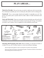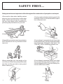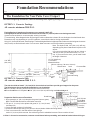
1
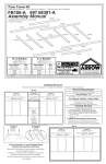
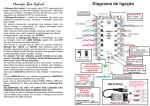
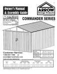
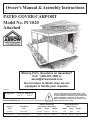
Owner's Manual & Assembly Instructions
BL01
PATIO COVER/CARPORT
Model No. PC1020
Attached
Missing Parts, Questions on Assembly?
Call: 1-800-851-1085 or
[email protected]
Do not return to dealer, they are not
equipped to handle your requests.
705120511
Storage Area:
197 Sq. Ft. 1692 Cu. Ft.
18,3 m2
47,9 m3
BUILDING DIMENSIONS * Size rounded off to the nearest foot
CAUTION: SOME PARTS HAVE SHARP EDGES. CARE
MUST BE TAKEN WHEN HANDLING THE VARIOUS PIECES
TO AVOID A MISHAP. FOR SAFETY SAKE, PLEASE READ
SAFETY INFORMATION PROVIDED IN THIS MANUAL
BEFORE BEGINNING CONSTRUCTION. WEAR GLOVES
WHEN HANDLING METAL PARTS.
Exterior Dimensions
(Roof Edge to Roof Edge)
Width
Depth
Height
Interior Dimensions
(Wall to Facia)
Width
Depth
Height
* Approx.
Size
Foundation
Size
10' x 20'
123" x 249"
120 3/4"
240 1/4"
106 1/2"
119"
238"
3,0 m x 6,0 m
312,4 cm x 632,5 cm
306,7 cm
610,2 cm
270,5 cm
302,3 cm
604,5 cm
102"
259,1 cm
BEFORE YOU BEGIN....
BO2
Owner's Manual
Before beginning construction, check local building codes regarding footings, location
and other requirements. Study and understand this owner's manual.
Important information and helpful tips will make your construction easier and more
enjoyable.
Instructions are supplied in this manual and contain all
appropriate information for your model. Review all instructions before you begin, and
during assembly, follow the step sequence carefully for successful results.
Assembly Instructions:
Foundation and Anchoring: Your patio cover/carport must be anchored to prevent
wind damage. A foundation is also necessary as a base in order to construct a square
and level unit. Anchoring and foundation materials are not included with your unit. Your
assembly instructions provide information on a few methods commonly used to secure
and level a patio cover/carport.
Parts and Parts List: Check to be sure that you have all the necessary parts for your
unit.
•All part numbers can be found on the parts. All of these numbers (before the -) must agree with the
numbers on the parts list.
•If you find that a part is missing, include the model number of your patio cover/carport and contact:
Arrow Shed, LLC
1101 North 4th Street
Customer Service Department
Breese, Illinois 62230
1-800-851-1085 or [email protected]
•Separate contents of the carton by the part number while reviewing parts list.
•Familiarize yourself with the hardware and fasteners for easier use during construction. These are
packaged within the carton. Note that extra fasteners have been supplied for your convenience.
2
PLAN AHEAD....
BO03
Watch the Weather: Be sure the day you select to install your unit is dry and calm.
Do not attempt to assemble your unit on a windy day. Be careful on wet or muddy ground.
Two or more people should work together to assemble your unit. One
person can position parts or panels while the other is able to handle the fasteners and
the tools.
Teamwork:
Tools and Materials: These are some basic tools and materials you will need for the
construction of your unit. Decide which method of anchoring and the type of foundation
you wish to use in order to form a complete list of the materials you will need.
Required
• Eye Goggles
• No. 2 Phillips Screwdriver
(With Hardened Magnetic Tip)
Note: A power screwdriver or variable speed drill with Phillips-tip attachment can speed assembly by
as much as 40%.
Required
• Work Gloves
• Step Ladder
• Utility Knife / Scissors
• Pliers
• Carpenter's Level
• Tape Measure
Optional Time-Savers
• Wrench / Nut Driver
• Electric / Cordless Drill
• Square
• String (for squaring frame)
Foundation Preparation
• Hammer and Nails
• Spade or Shovel
• Hand Saw / Power Saw
• Lumber and/or Concrete
Selecting and Preparing Your Site: Before assembly, you will want to decide on
a location for your unit. The best location is a level area with good drainage.
•Allow enough working space for ease of moving parts into position during assembly.
•Before you begin the first steps in assembling your parts, a foundation should be constructed and
an anchoring system should be ready to use.
3
SAFETY FIRST....
BO04
Safety precautions are important to follow throughout the construction of your patio cover/carport
•Care must be taken when handling various
pieces of your unit since some contain sharp
edges. Please wear work gloves, eye protection and long sleeves when assembling or
performing any maintenance on your unit.
•Practice caution with the tools being used in the
assembly of this unit. Be familiar with the operation of all power tools.
safety edge
sharp edge
sharp edge
safety edge
•Keep children and pets away from worksite to
avoid distractions and any accidents which
may occur.
•Do not attempt to assemble the unit if parts are
missing because any unit left partially assembled
may be seriously damaged by light winds. Call
1-800-851-1085 or [email protected]
•Never concentrate your total weight on the
roof of the unit. When using a step ladder make
sure that it is fully open and on even ground
before climbing on it.
•Do not attempt to assemble the unit on a windy
day, because the large panels acting as a "sail",
can be whipped about by the wind making construction difficult and unsafe.
4
CARE & MAINTENANCE....
BO05
For long lasting finish, periodically clean and wax the exterior surface. Touchup scratches as soon as you notice them on your unit. Immediately clean the area with
a wire brush; wash it and apply touch-up paint per manufacturer's recommendation.
Finish:
Roof: Keep roof clear of leaves and snow with long handled, soft-bristled broom. Heavy
amounts of snow on roof can damage unit, making it unsafe.
Regularly check your unit for loose screws, bolts, nuts, etc. and retighten
them as necessary.
Fasteners:
Other Tips....
• Wash off inked part numbers on coated panels with soap and water.
Keep this Owner's Manual and Assembly Instructions for future reference.
5
Foundation Recommendations
BL06
The Foundation For Your Patio Cover/Carport
Note: Before beginning construction, check local building codes regarding footings, location and other requirements.
OPTION 1: Concrete Footings
All concrete minimum 2500 P.S.I.
Footing Bearing is based on soil pressures not to exceed 1,000 P.S.F..
Footing Depth to extend to below frost line but not less than 12" (30,5 cm) where new footings are used.
If posts are not anchored to a concrete slab, a footing is needed.
To locate footing, follow diagram below. Dig footing the minimum dimensions shown. Be sure footings are level with each other.
Dimensions may vary depending on your soil conditions, consult local codes for footing requirements.
Using 3/4" (19 mm) thick boards, frame footings. The board height will be the height required to make sure the footings and concrete
slab (if used) are level with each other. Pour concrete. Allow concrete to cure 24 hours before proceeding.
Note: The depth of slab, 123" (312,4 cm), will vary
depending upon place of attachment for patio cover/
carport.
If you mount a 2x4/2x6 (38 mm x 89 mm / 38 mm x
140 mm) on wall, you will need to add 1 1/2" (3,8
cm). If you mount to the eave, you will need to add
the length of the eave.
117 1/2" (298,5 cm)
*From wall or
Mounted 2x4/2x6
(38 mm x 89 mm / 38 mm x 140 mm)
123" Min.
(312,4 cm)
Level
Wood Frame
7"
(17,8 cm)
Min.
117 1/2"
117 1/2"
(298,5 cm) Min. 249" (298,5 cm)
(632,5 cm)
OPTION 2: Concrete Slab
All concrete minimum 2500 P. S. I.
7"
(17,8 cm)
Min.
12" (30,5 cm)
5 1/2"
Min.
(14,0 cm)
Min.
Concrete Slab
Earth
Concrete Footing
12"
(30,5 cm)
Min.
The slab should be at least 4" (10,2 cm) thick. It must be level and flat to provide good support for the posts.
The following are the recommended materials for your foundation.
● 2 x 4's (38 mm x 89 mm) (will be removed once the concrete cures)
● Concrete ● Sheet of 6 mil plastic ● 6"x6" (15,2 cm x 15,2 cm) reinforcing mesh ● sand ● gravel
Concrete
Grade Level
4" (10,2 cm) Min.
Prepare the Site/Construct a Foundation
6"x6" (15,2 cm x
1. Dig a rectangle, 10" (25,4 cm) deep into the ground (remove grass).
15,2 cm) Mesh
Note: Finished Slab dimensions, with lumber removed.
Plastic Barrier
Earth
2. Fill up to 4" (10,2 cm) in the square with gravel, 2" (5,1 cm) of sand,
2" (5,1 cm) Sand
and tamp firm.
4" (10,2 cm)
3. Cover sand with a sheet of 6 mil plastic.
Gravel Bed
4. Construct a wood frame using 2 x 4 (38 mm x 89 mm) lumber. Make reinforcing stakes.
5. Pour in concrete to fill in the hole and the frame giving a
total of 4" (10,2 cm) thick concrete. Use reinforcing mesh in embedded concrete. Be sure surface is level.
6 Allow 5 - 8 hours for construction, concrete cure 24 hours before proceeding, and a week to harden before driving on.
Hardware
BL07
66623
#10Ax3/8" (10 mm)
Screw (96)
66629
3/8-16x3 1/4" (83 mm)
Hex Hd Bolt (3)
66433
3/8-16 Hex Nut (3)
66625
#10-32x3/4"(19 mm)
Bolt (20)
(Packed with Screws)
66628
#10-32x7/16"(11 mm)
Bolt (44)
(Packed with Screws)
66624
#10-32 Well-Nut (20)
(Packed with Screws)
65106
#10-32 Square Nut (44)
(Packed with Screws)
7
Parts List
BL08
Assembly
Key No.
1
2
3
4
5
6
Part
Number
9654
9657
9664
9667
9668
66626
7
66627
8
9
10
11
12
13
14
15
16
17
18
9652
9656
9665
9669
9670
9661
9671
9660
9673
9674
9655
Assembly
Key No.
19
21
Part
Number
9662
9653
Assembly
Key No.
20
21
Part
Number
9663
9653
8
Parts in Carton One
Part
Quantity Check
Description
in Carton List
Right Facia
2
Left Facia
2
Top Front Trim
2
Top Left End Trim
1
Top Right End Trim
1
Weather Seal 3/16 x 2"
(5 mm x 5,1 cm)
1
Weather Seal 1/2 x 1 1/2"
(13 mm x 3,8 cm)
2
Anchor Bracket
3
Roof Channel
4
Channel Brace
2
Front Splice Trim
3
Corner Trim
4
Left Post
1
Center Post
1
Right Post
1
Left Rear Roof Channel
1
Right Rear Roof Channel
1
Top Trim Cap
2
Parts in Carton Two
Part
Description
Right Roof Panel
Main Roof Panel
Parts in Carton Three
Part
Description
Left Roof Panel
Main Roof Panel
Quantity Check
in Carton List
1
4
Quantity Check
in Carton List
1
4
Assembly by Key No.
BL09
9
● Parts Needed For ●
Step 1
Rear Roof Channel
Pre-Assemblies
BL10
● 9673 Left Rear Roof Channel (one)
● 9674 Right Rear Roof Channel (one)
● 9665 Channel Brace (two)
The rear roof channel assemblies
attach to the permanent structure
and support the unit.
1 Fasten the channel braces to the
end of the left & right rear roof
channel using four #10-32x7/16"
(11 mm) bolts and square nuts.
Hint: Position the short and long
flange as shown in the diagram.
Long Flange
9665
9674
Short Flange
9673
Long Flange
9665
Short Flange
10
● Parts Needed For ●
Step 2
Post
Pre-Assemblies
BL11
● 9661 Left Post (one)
● 9671 Center Post (one)
● 9660 Right Post (one)
● 9652 Anchor Bracket (three)
The anchor brackets in this step will
be used later to anchor the unit to the
base/foundation.
1
Position an anchor bracket inside the left, center & right posts,
align holes, and fasten using a 3/816 x 3 1/4" (83 mm) hex head bolt
and hex nut. Make three assemblies.
Do not overtighten.
9661 or 9671 or 9660
9652
3/8-16x3 1/4" (83 mm)
Hex Head Bolt
3/8-16 Hex Nut
11
● Parts Needed For ●
Step 3
Mounting Rear Roof
Channels to Structure
BL12
● Rear Roof Channel Assembly (two)
● 66627 Weather Seal
1/2x 1 1/2 (13 mm x 3,8 cm) (two)
1 Positioning The height from the bottom of post to the bottom of rear roof channel is 8'-8 1/2" (265,4
cm) minimum to 9' (274,3 cm) maximum. For unit installed over a door, in order to maintain door clearance, the
minimum height above door is 6" (15,2 cm). If distance is less than 8'-8 1/2" (265,4 cm), bottom of posts will have
to be trimmed (with hacksaw) in order to obtain 2 1/2" (6,4 cm) slope. If this is necessary, drill two new holes in
post and re-attach anchor. For installation where a door is not involved, do not block windows with rear roof
channels. Once dimensions are established, level rear roof channels and mark structure.
9673
Level
6" (15,2 cm) Min.
9674
9665
9665
8'-8 1/2" (265,4 cm) Min.
9' (274,3 cm) Max.
Post
END VIEW
Concrete
2 Channel Weather Stripping
Attach weather stripping 1/2x 1 1/2 (13 mm x 3,8 cm) to one
end, on the outside of rear roof channel. Making sure weather stripping is flush with top flange of rear roof
channel, continue to stick weather stripping to rear roof channels. Peel paper backing.
Rear Roof Channel Assemblies
1/2x1 1/2 (13 mm x 3,8 cm)
Weather Seal
12
Step 3 continued....
BL13
3 Attaching It is important that the rear roof channels be securely anchored to a sound and flat mounting
surface. A special mounting board (2x4,2x6)x19' 10" (38 mm x 89 mm, 38 mm x 140 mm) x 604,5 cm can be
used if existing surface is questionable or on mobile homes. The mounting board should be attached with wood
screws drilled into the wall studs on frame construction. Masonary anchors should be used on brick or masonary
installations. Also on frame construction, if stud or rafter spacing is greater than 16" (40,6 cm) on center, use the
mounting board. Countersink all fasteners.
Attach at each stud
12" m)
c
0
3
( ,5
Note: Poke a hole through weather seal
using an awl before drilling or fastening.
Countersink Screws
Option 1 Attachment to Stud or Rafter Locate studs or rafters in mounting wall. With
rear roof channel level on wall, drill a 3/16" (5 mm) hole, 1" (2,5 cm) from top flange, through rear roof channel's
web and wall at every stud or rafter. Make sure there is a hole on each end of channel. Remove rear roof channel
from wall and enlarge holes in rear roof channel with a 7/16" drill bit. This hole will enable the fastener to pass
through the rear roof channel. Align holes in wall with holes in rear roof channel. Attach rear roof channel to wall
with 3/8"x2 1/2" (10 mm x 6,4 cm) screws and washers, provided your local code permits the use of this screw.
Note: If a special mounting board was used, holes are provided in rear roof channel for attaching to wall.
Weather Seal
Attach at each stud
3/8" x 2 1/2" (10 mm x 6,4 cm)
Lag Screw & Washer
into Wall Stud
Option 2 Attachment to Brick or Masonary
Use masonary fasteners (purchased
locally) 12" (30,5 cm) on center. Level rear roof channel on wall, using holes in rear roof channel as a guide,
drill holes in wall at the center and each end of channel with proper size masonary bit ( do not drill holes in mortar
joints). Attach rear roof channel to wall with masonary anchors. Repeat procedure for remaining holes in rear
roof channel. Note: If a special mounting board was used, holes are provided in rear roof channel for attaching
to wall.
Weather Seal
12" m)
c
0
3
( ,5
Masonary Anchor
13
● Parts Needed For ●
Step 4
● 9656 Roof Channel (four)
● Post Assemblies (three)
Roof Channel
Assembly
BL14
Get help holding post in place while
attaching the roof channel.
1 Position a roof channel, with small
hole 1 1/8" (2,9 cm) from end at left
post, and fasten to channel brace using four #10-32x 7/16" (11 mm) bolts
and square nuts. Fasten other end to
the top end of the left post, noting
location of lock seam, using two #1032x7/16" (11 mm) bolts and square
nuts, and two #10Ax3/8" (10 mm)
screws.
STEP
1
Lock Seam
2 Fasten a roof channel, with small
hole 1 1/8" (2,9 cm) from end, to the
front of left post, using the same fasteners, with opposite end overlapping
center post by 1 1/2" (3,8 cm), fasten
as before. Brace center of unit with
2x4's (38 mm x 89 mm) as shown.
#10-32 Square Nut
9656
1 1/8"
(2,9 cm)
#10-32x7/16"
(11 mm) Bolt
3
Repeat procedure with next roof
channel, to center and right post.
9661 Left Post
#10Ax3/8"
(10 mm) Screw
4
Repeat procedure with next roof
channel, as done in Step 1 to right post
and channel brace.
STEP
2
1 1/8"
(2,9 cm)
1 1/8"
(2,9 cm)
9656
9671 Center Post
14
Step 4 continued....
BL15
9660 Right Post
9671 Center Post
STEP
1 1/8" (2,9 cm)
3
9656
STEP
4
9660 Right Post
1 1/8"
(2,9 cm)
9656
1 1/8"
(2,9 cm)
15
● Parts Needed For ●
Step 5
● 9654 Right Facia (two)
● 9657 Left Facia (two)
Facia Assembly
BL16
1
Place right and left facia over
front roof channels with largest
amount of holes on top. Butt together
and fasten bottom flange with ten
#10Ax 3/8" (10 mm) screws. Fasten
top flange using six #10 screws where
shown.
STEP
3
Press firmly against mounting surface
#10-32 Well-Nut
2 Place right and left facia over end
STEP
2
roof channels. Fasten bottom flange
with five #10 screws. Fasten top
flange in the same manner.
9654
3 Place a
well-nut on top flange of
the front right and left facia. Insert all
the way into pre-drilled hole until
flange is firmly against mounting surface. Continue along length of the
front right and left facia pieces.
9657
STEP
9654
1
Overlap
Post
9657
Facia
Roof Channel
16
● Parts Needed For ●
Step 6
Corner/Front Splice
Trim
BL17
● 9670 Corner Trim (four)
● 9669 Front Splice Trim (three)
1 Fasten front splice trim to the
seam where front facia meets with
four #10 screws.
2 If a special mounting board was
used, use remaining front splice trim
pieces to cover ends of board, instead of corner trim. Fasten using
two #10 screws.
3
Position corner trim to inside
corners with short flange to facia and
fasten with two #10Ax3/8" (10 mm)
screws. Position corner trim to outside corners with long flange on the
front facia, and fasten with four #10
screws.
Repeat procedure on opposite end
of unit.
STEP
3
9670
Mounting Board
9669
STEP
9670
9670
9669
2
STEP
1
Short Flange
9670
Long Flange
17
Step 7
● Parts Needed For ●
Roof Assembly
BL18
● 9662 Right Roof Panel (one)
● 9653 Main Roof Panel (eight)
● 9663 Left Roof Panel (one)
● 66626 Weather Seal
3/16x 2 (5 mm x 5,1 cm) (one)
1 Attach weather stripping 3/16x2 (5
mm x 5,1 cm) to one end, on the
inside of rear roof channels. Continue to stick weather stripping to rear
roof channels. Peel paper backing.
2
Fasten top of right roof panel
using two #10-32x7/16" (11 mm) bolts
and square nuts into bottom flange,
on rear roof channel. Fasten bottom
of panel using two #10-32x3/4" (19
mm) bolts into front facia. Pass bolt
through panel and tighten until snug.
Do not over-tighten.
To square unit, measure diagonally. Make
sure both diagonal measurements are the
same. These measurements are taken from
opposite ends of facia and rear wall channel.
Measure from the top outside edge of facia to
the top outside edge of the rear wall channel.
If diagonal dimensions are not the same,
adjust assembled facia section left to right
until the diagonals are equal.
Diagonal Measurement
Rear Roof Channel Assemblies
IMPORTANT
2x4's (38 mm x 89 mm) centered
under roof panel will help you
align the holes
3 Lock a main roof panel and right
roof panel together and slide into the
rear roof channel. We recommend
that the two mating edges are lubricated with a liquid detergent when
sliding into the channel. Use a 2x4
(38 mm x 89 mm) and hammer to
lightly tap roof panels into place. Be
sure entire rib on roof panels are
interlocked together.
4 Fasten top and bottom of panel in
Level
Concrete Slab
Rear Roof Channel Assemblies
the same manner. Fasten overlapping ribs to rear roof channel using a
#10Ax3/8" (10 mm) screw.
5 Continue installing the remaining
seven main and the left roof panel
as before.
NOTE
Leave out outer rib screw for trim
piece in the next assembly step
on the right and left roof panel
18
3/16 x 2 (5 mm x 5,1 cm)
Weather Seal
STEP
1
Step 7 continued....
BO19
Do not fasten until next step
END
VIEW
2x4
(38 mm x
89 mm)
END
VIEW
Fasten
Overlapped
Ribs
9662
STEP
2
2x4
(38 mm x 89 mm)
#10-32 Square Nut
#10Ax3/8" (10 mm) Screw
2x4
(38 mm x 89 mm)
#10-32x7/16"
(11 mm) Bolt
#10-32x3/4"
(19 mm) Bolt
STEP
5
END
VIEW
9653
STEP
4
2x4
(38 mm x 89 mm)
#10-32 Well-Nut
STEP
3
Interlock Ribs
19
● Parts Needed For ●
Step 8
BL20
Top Left and Right
End Trim
● 9667 Top Left End Trim (one)
● 9668 Top Right End Trim (one)
1 Fasten top right end trim to the
outer right roof panel rib using four
#10Ax3/8" (10 mm) screws. Do not
fasten the bottom hole until the next
step.
2 Repeat procedure for the top left
end trim on the outer left roof panel
rib.
#10Ax3/8" (10 mm) Screw
Do not fasten until next step
9667
STEP
STEP
2
1
9668
END
VIEW
20
● Parts Needed For ●
Step 9
Top Front Trim
● 9664 Top Front Trim (two)
● 9655 Top Trim Cap (two)
BL21
1 Position top front trim to ends of
roof panels, overlapping top left end
trim and fasten using five #10 screws.
2
Overlap with next top front trim
and fasten together using six #10
screws along length.
3 Cover seams where trims meet at
the corners with top trim caps using
four screws.
STEP
STEP
1
Overlap
2
#10Ax3/8" (10 mm) Screw
9664
9664
9655
#10Ax3/8" (10 mm)
Screw
STEP
3
21
Step 10 Leveling and Anchoring Posts
BO22
Check to be sure front facia and rear
roof channel are still square. Level
each post. Stand at one end and
visually check the alignment of the
post. Once all posts are aligned, mark
fastener location using holes in bottom flanges of anchor bracket as a
guide.
Facia
Masonary
Using a masonary
bit, drill holes to fit masonary fasteners (not provided). Attach bottom
flanges of anchor bracket to slab or
footing, using instructions packed
with masonary fasteners.
Post
Deck Using a wood bit, drill holes
Level
to fit wood fasteners (not provided).
Attach bottom flanges of anchor
bracket to deck, using instructions
packed with wood fasteners.
Anchor Bracket Flange
Post
Pencil
Masonary Anchors
Anchor Bracket Flange
22
Drill
Suggested Guttering System (not included)
BL23
If the locality where you have installed the
patio cover/carport could benefit from a guttering system, we recommend the following
list of materials, (not included).
● Two 10' (304,8 cm) gutters with splice
or
● One 20' (609,6 cm) gutter
● One downspout
● One outlet
● One right & One left end cap
● Sealant
● Nine hidden hangers
with nine 1 1/2" (38 mm) bolts and nuts
● Three standard elbows
● Two bands
with four sheet metal screws
Outlet
Gutter
Left End Cap
Elbow
Elbow
Band
Post
1 Assemble the gutter on the ground using
Downspout
sealant.
Screw
2 Temporarily remove top front trim, lift assembly to unit and mark top left and right end
trim where gutter meets trim. Remove gutter
system and notch (using tin snips) top L&R
end trim so gutter fits flush along front of unit.
Elbow
3
Evenly space out five hidden hangers in
gutter, making sure one is in the outlet. Attach
gutter assembly to front facia/ front roof channel using five 1 1/2" (38 mm) bolts and nuts
through hidden hangers. Replace top front
trim.
Top Front Trim
4 Assemble the downspout on the ground.
5 Hold in place on outlet. Attach to post with
two bands. Drill 3/32" (2 mm) holes and fasten
with sheet metal screws.
Top End Trim
1 1/2" (38 mm) Bolt
Hidden Hanger
Nut
Notch
Gutter
23
PC1020
BL24
SOME FACTS ABOUT RUST
Rusting is a natural oxidizing process that occurs
when bare metal is exposed to moisture. Problem
areas include screw holes, unfinished edges, or
where scrapes and nicks occur in the protective
coating through normal assembly, handling and
use. Identifying these natural rusting problem areas
and taking some simple rust protection precautions
can help to stop rust from developing, or stop it
quickly as soon as it appears.
1. Avoid nicking or scraping the coating surface,
inside and out.
2. Keep roof and post perimeter free of debris and
leaves which may accumulate and retain moisture.
These can do double damage since they give off
acid as they decay.
3. Touch up scrapes or nicks and any area of visible
rust as soon as possible. Make sure the surface is
free of moisture, oils, dirt or grime and then apply an
even film of high quality touch-up paint.
705120511