1
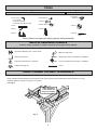
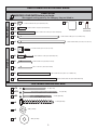
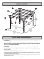
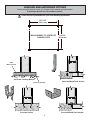
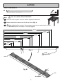
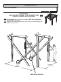
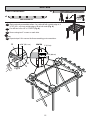
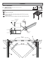
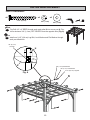
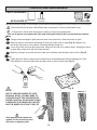
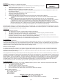
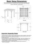
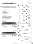
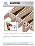
16712-GN
STOP!
Call Us First!
DO NOT RETURN TO STORE.
For immediate help with assembly or product information
call our toll-free number:
1-888-827-9056
or email:
[email protected]
Our staff is ready to provide assistance.
April through October M - F 8:00 AM to 7:00 PM EST
Saturday 8:30 AM to 4:30 PM EST
November through March M - F 8:00 AM to 5:00 PM EST
(This page intentionally left blank.)
ASSEMBLY MANUAL
16712-GN
12/17/2013
PERGOLA 10' x 12' (305 x 366 cm)
KEEP THIS MANUAL FOR FUTURE REFERENCE
IMPORTANT!
READ INSTRUCTIONS THOROUGHLY PRIOR TO BEGINNING ASSEMBLY.
BEFORE YOU BEGIN
• BUILDING RESTRICTIONS AND APPROVALS
Be sure to check with local building department and homeowners association for speci c restrictions and/ or requirements before building.
• ENGINEERED DRAWINGS
Contact our Customer Service Team if engineered drawings are needed to pull local permits.
• SURFACE PREPARATION
To ensure proper assembly you must build your pergola on a level surface.
• CHECK ALL PARTS
Inventory all parts listed on pages 3. Contact our Customer Service Team if any parts are missing or damaged.
• LEVELING AND ANCHORING
You may choose to anchor your pergola. See page 5 for optional methods of leveling and anchoring your pergola.
- CUSTOMER SERVICE Call: 1-888-827-9056 email: [email protected]
TOOLS
Required
❑ Drill / Driver
❑ Tool Belt/
Nail Pouch
❑ Tape Measure
❑ 1/8" Drill Bit
❑ #2 Philips Drive Bit
❑ #2 Square Drive Bit (Included)
❑ Hammer
❑ Safety Glasses
❑ Level
❑ Gloves
❑ Ladder
❑ Pencil
❑ Square
Optional
or
❑ Dremel
Safety! Always use approved safety glasses during assembly.
HELPFUL REMINDER SYMBOLS
Look for these symbols for helpful reminders throughout this manual.
= Assistance Required; two or more people.
= Mark part with pencil.
= Ensure squareness.
BEGIN
= Beginning of steps for assembly or installation.
= Important required step or operation.
FINISH
= You have finished the assembly or installation.
= Helpful assembly hint.
= Level
ORIENT LUMBER FOR BEST APPEARANCE
Always install the material leaving the best edge and best surface visible. Please remember that these blemishes in no way
negatively affect the strength or integrity of our product.
(See Fig. A)
Orient blemishes
to face inward and
away from visibility.
Fig. A
2
PARTS IDENTIFICATION AND SIZES
PARTS LIST
INVENTORY YOUR PARTS before you begin.
We suggest sorting parts by the category they are listed in.
RAFTERS
x20
x4
x1
1-3/8 x 3-3/8 x 8-1/2" (3,5 x 8,6 x 21,6 cm)
N
x1
3-3/8 x 3-3/8 x 14" (8,6 x 8,6 x 35,6 cm)
Sandpaper
x30
M
x8
J
x4
K
x4
POSTS
L
F
1-3/8 x 3-3/8 x 39-11/16" (3,5 x 8,6 x 100,8 cm)
1-3/8 x 5-3/8 x 138" (3,5 x 13,7 x 350,5 cm)
1-3/8 x 5-3/8 x 162" (3,5 x 13,7 x 411,5 cm)
1 x 4-3/4 x 4-3/4" (2,5 x 12,1 x 12,1 cm)
x8
E
x8
D
3-3/8 x 3-3/8 x 37" (8,6 x 8,6 x 94 cm)
O
3/4 x 1-1/2 x 37" (1,9 x 3,8 x 94 cm)
x8
x8
G
x4
H
7/8 x 3-3/8 x 11-7/8" (2,2 x 8,6 x 30,2 cm)
7/8 x 5-3/8 x 90-1/2" (2,2 x 13,7 x 229,9 cm)
3-3/8 x 3-3/8 x 103-1/2" (8,6 x 8,6 x 262,9 cm)
FASTENER/HARDWARE BAG
x70
2" (5,1 cm)
x270
3" (7,6 cm)
x80
2-1/2" (6,4 cm)
3-1/2” (8,9 cm)
x8
x8
x8
Micro-Shade
Concentrate
3/8” (1,0 cm)
3/8” (1,0 cm)
3
PERGOLA ANATOMY
M
F
N
K
D
J
L
O
90-1/2"
229,9 cm)
G
H
132-1/16"
(335,4 cm)
INSIDE
POST
109-3/4"
(278,8 cm)
INSIDE
POST
142-13/16"
362,7 cm)
E
OUTSIDE
POST
120"
304,8 cm)
OUTSIDE
POST
CARE AND MAINTENANCE
❑ The wood in your pergola has been treated with a process called ProWood Micro for resistance to fungal decay and
insect infestation.
❑ The color of your pergola is from a process called MicroShade ™ and involves adding pigment into the wood as it is
pressure treated. This process results in colorant throughout the wood which helps minimize surface markings being
visible. The appearance of your pergola with MicroShade will last about two years with no stain application. Over time
the color of the pergola wood will slightly darken.
❑ If you want, you may apply a water repellent which will benefit the wood and help minimize splitting, checking and
surface cracking.
❑ Checking, splitting and surface cracking are characteristics of all wooden structures. This is caused by varying
seasonal temperatures and moisture conditions. To minimize this checking and/or cracking you may coat your pergola
with a water repellent.
❑ A wood stain may be applied to your pergola if you choose.
❑ For minor touch-up we have included sandpaper and some MicroShade concentrate. Refer to page 26 of this manual
for our suggested procedure for minor touch-up.
❑ We suggest you inspect all hardware and fasteners used to assemble your pergola for any deterioration or looseness.
Re-tighten hardware as required.
4
LEVELING AND ANCHORING OPTIONS
There are multiple ways to anchor your Pergola. A few methods are shown below.
Anchoring materials are not included in this kit.
Check anchoring methods with your local building department.
137-7/16"
(349,1 cm)
MEASUREMENT TO CENTER OF
CORNER POSTS
114-7/8"
(291,8 cm)
Solid
Masonry block
On-Grade Leveling Method
Gravel for drainage
Concrete Anchor
Concrete/Wood Deck Anchor
Concrete/Wood Deck Anchor
5
RAFTERS
PARTS REQUIRED:
x8
J
1-3/8 x 5-3/8 x 138" (3,5 x 13,7 x 350,5 cm)
YOU WILL MARK ONE RAFTER FIRST!
BEGIN
1
Place one 138” long rafter as shown with the angled end downward.
2
Measure and mark locations at top of rafter as shown (Fig. A).
Align all J rafters flush at ends. Using a square, use previously marked rafter to mark
ALL EIGHT rafters consistently on top edge (Fig. B).
3
121-3/4”
(309,2 cm)
116-3/4”
(296,5 cm)
96-5/8”
(245,4 cm)
71-1/2”
(181,6 cm)
46-3/8”
(117,8 cm)
21-1/4”
(54 cm)
91-5/8”
(232,7 cm)
66-1/2”
(168,9 cm)
41-3/8”
(105,1 cm)
16-1/4”
(41,3 cm)
Fig. A
J
NOTE:
Angle down
Flush
Fig. B
Flush
ALL MARKS
6
RAFTERS
PARTS REQUIRED:
x20
x40
3" (7,6 cm)
L
1-3/8 x 3-3/8 x 8-1/2" (3,5 x 8,6 x 21,6 cm)
x2
J
1-3/8 x 5-3/8 x 138" (3,5 x 13,7 x 350,5 cm)
1/8" (0,3 cm)
Drill Bit
4
Orient two J rafters as shown on flat surface with angled edge down.
5
Marks holes on face of rafter centered on marks as shown (Fig. A).
6
Pre-drill 1/8" (0,3 cm) holes through rafter at marks.
7
Center rafter ends L on marks and flush to top as shown (Fig. B, C).
FINISH
8
Secure rafter ends flush to top of rafter using two 3" screws per rafter end.
J x2
NOTE:
Angle down
3/4" (1,9 cm)
2" (5,1 cm)
Centered
on marks.
Fig. A
L x20
Flush
J x2
Fig. B
Center
on marks.
Flush
Fig. C
(2) 3" (7,6 cm) Screws
7
CORNER POSTS
PARTS REQUIRED:
x8
x64
2-1/2" (6,4 cm)
G
7/8 x 5-3/8 x 90-1/2" (2,2 x 13,7 x 229,9 cm)
x4
H
1/8" (0,3 cm)
Drill Bit
3-3/8 x 3-3/8 x 103-1/2" (8,6 x 8,6 x 262,9 cm)
BEGIN
1
Position post face G on top of post H flush at end and with a 1” overhang on
each side (Fig. A).
2
Secure using eight 2-1/2” screws on each side. Pre-drilling is optional.
3
Flip post and face over and install a second post face as shown.
FINISH
4
Repeat steps 1-3 to assemble three more posts.
1"
(2,5 cm)
29-1/2"
(74,9 cm)
1-11/16"
(4,3 cm)
G
2"
(5,1 cm)
1"
(2,5 cm)
1"
(2,5 cm)
Ends Flush
Fig. A
H
x4
8
1-11/16"
(4,3 cm)
CORNER POSTS
PARTS REQUIRED:
x4
x16
3" (7,6 cm)
K
1/8" (0,3 cm)
Drill Bit
1-3/8 x 5-3/8 x 162" (3,5 x 13,7 x 411,5 cm)
BEGIN
1
3
Arrange parts as shown on a level surface. Both post assemblies should
be approximately parallel and flush at each end.
Measure and mark 134" centered on rafter. Locate mark to inside
of post (Fig. A,B).
Pre-drill two holes 1/8" x 2" DEEP diagonally as shown (Fig. B).
4
Secure rafter to corner post using two 3" screws (Fig. A).
5
With some assistance carefully flip post and rafter over to attach second side.
2
Flush
FINISH
6
Repeat steps 1-5 to assemble second side.
K
134"
(340,4 cm)
Fig. A
134" (340,4 cm)
CENTERED
Flush
G
Flush
3" (7,6 cm)
Screws
Flush
K
H
x2
Flush
Fig. B
9
CORNER POSTS
PARTS REQUIRED:
x4
x8
3" (7,6 cm)
J
1-3/8 x 5-3/8 x 138" (3,5 x 13,7 x 350,5 cm)
IMPORTANT!
BEGIN
1
2
GET A HELPER TO ASSIST YOU FOR SAFETY AND
STABILITY DURING THIS PROCEDURE.
Measure and mark four rafters as shown (Fig. A). Pre-drill 1/8" (0,3 cm)
hole through rafter.
Raise rafter assembly on level surface (Fig. B). HINT: Place a protective
material under rafter end.
3
Place marked rafter boards angled toward top of post.
4
Level both corner posts on both sides and secure to braces using two 3" (7,6 cm)
screws for support at each side of BOTH Post & Rafter Assemblies (Fig. C).
16-1/4”
(41,3 cm)
2-3/4”
(7 cm)
Fig. A
Fig. B
Pre-drilled hole
Center on G.
(2) 3" (7,6 cm)
Screws
HINT: Place a protective
material under rafter end.
Fig. C
10
CORNER POSTS
PARTS REQUIRED:
IMPORTANT!
GET A HELPER TO ASSIST YOU FOR SAFETY AND
STABILITY DURING THIS PROCEDURE.
5
6
Repeat steps 1-4 to raise second assembly. HINT: Place a protective
material under rafter end.
Separate two raised assemblies 120" (304,8 cm) from outside edges with
supports angled inward.
142-13/16”
(362,7 cm)
120”
(304,8 cm)
HINT: Place a protective
material under rafter end.
11
RAFTERS
PARTS REQUIRED:
x8
3" (7,6 cm)
x2
1/8" (0,3 cm)
Drill Bit
PRE-ASSEMBLED
7
8
Rest previously assembled rafters J on rafters K with outside edge of J
9-7/8" (25,1 cm) from outside edge of G at both ends (Fig. A).
Pre-drill two holes 1/8" x 2" DEEP (Fig. A).
9
Secure using two 3" screws on each side.
FINISH
10 Repeat steps 6-9 to secure the three remaining post connections.
G
9-7/8” (25,1 cm)
CENTER
1” (2,5 cm)
3-1/2” (8,9 cm)
K
Fig. A
J
12
CORBELS
PARTS REQUIRED:
x4
D
3-3/8 x 3-3/8 x 37" (8,6 x 8,6 x 94 cm)
1/8" (0,3 cm)
Drill Bit
BEGIN
1
Square post and rafter.
2
Position corbels D on flat surface and pre-drill 1/8" (0,3 cm) holes
through as shown.
3
Position corbels flush to top edge of outer main rafter K and post H.
1/8" (0,3 cm)
Pre-drill
2” (5,1 cm)
2” (5,1 cm)
1” (2,5 cm)
1/8" (0,3 cm)
Pre-drill
1” (2,5 cm)
Flush
J
D x4
Flush
Flush
H
G
13
CORBELS
PARTS REQUIRED:
3
x12
3" (7,6 cm)
Attach upper end of corbel D to rafter K with one 3” (7,6 cm) screw. Use
two 3” (7,6 cm) Screws into Corner Post H at lower end of Corbel through
the Pre-Drilled holes.
FINISH
4
Repeat steps 1-3 to attach three more corbels.
J
Flush
3” (7,6 cm)
3” (7,6 cm)
D x4
3”
(7,6 cm)
Flush
G
3” (7,6 cm)
14
SQUARING PERGOLA
PARTS REQUIRED:
x2
BEGIN
1
Remove rafter supports (Fig. A).
2
Check post spacing and ensure diagonal measurement is 183-7/8" (467 cm).
Ensure posts are plumb.
Measurement to
outside of posts.
Fig. A
183-7/8"
(467 cm)
Measurement to
outside of posts.
Measurement to 142-13/16"
outside of posts. (362,7 cm)
120"
(304,8 cm)
15
CORBELS
PARTS REQUIRED:
x4
D
x16
3" (7,6 cm)
3-3/8 x 3-3/8 x 37" (8,6 x 8,6 x 94 cm)
3
Check rafter and post are square.
4
Position corbels flush to top edge of outer main rafter K and post H.
5
Attach upper end of corbel D to rafter K with two 3” (7,6 cm) Screws. Use
two 3” (7,6 cm) Screws into Corner Post H at lower end of Corbel through
the Pre-Drilled holes.
FINISH
6
Repeat steps 3-5 to attach three remaining corbels.
J
Flush
D x4
G
G
K
Flush
3” (7,6 cm)
3” (7,6 cm)
K
G
D x4
3” (7,6 cm)
16
H
LADDER SUPPORTS
PARTS REQUIRED:
x30
x120
3" (7,6 cm)
M
1-3/8 x 3-3/8 x 39-11/16" (3,5 x 8,6 x 100,8 cm)
x2
J
1-3/8 x 5-3/8 x 138" (3,5 x 13,7 x 350,5 cm)
1/8" (0,3 cm)
Drill Bit
BEGIN
1
Orient two J rafters as shown on flat surface with angled edge down and
marked edge up.
2
Mark holes on face of rafter centered on marks as shown (Fig. A).
3
Pre-drill 1/8" (0,3 cm) holes as shown through rafter.
FINISH
4
Secure rafter supports flush to top of rafter using two 3" (7,6 cm) screws per support (Fig. A).
Repeat steps 1-4 to make two more ladder supports.
M
Flush
3/4" (1,9 cm)
NOTE:
Angled
end down
2" (5,1 cm)
(2) 3" (7,6 cm)
screws
Fig. A
M x10
Flush
J
J
x3
17
LADDER SUPPORTS
PARTS REQUIRED:
BEGIN
1
Elevate one end of ladder assembly onto main rafter first, then elevate the
other end of Ladder to rest across rafters.
2
Slide ladder assembly against both posts as shown.
18
LADDER SUPPORTS
PARTS REQUIRED:
x8
3
Repeat step 1 to place remaining ladder assemblies on rafters.
4
Align ladder assemblies flush with installed rafter ends.
3" (7,6 cm)
FINISH
5
Secure outside ladder assemblies using two 3” (7,6 cm) screws at each corner
into posts H.
Flush
(2) 3" Screws
(7,6 cm)
19
INTERMEDIATE POSTS
PARTS REQUIRED:
x4
N
3-3/8 x 3-3/8 x 14" (8,6 x 8,6 x 35,6 cm)
BEGIN
1
2
Position both Intermediate Posts N between main rafters K revealing
1-1/2” (3,8 cm) on bottom.
Align ladder assemblies flush with installed rafter ends.
1-1/2” (3.8 cm)
N
Flush
N
20
INTERMEDIATE POSTS
PARTS REQUIRED:
3
x20
3" (7,6 cm)
Using four 3" (7,6 cm) screws secure ladder assemblies to corbels
FINISH
4
Secure intermediate spacers to rafters K and J using four
3" (7,6 cm) screws.
K
J
J
N
N
K
21
CORBEL COVERS
x36
PARTS REQUIRED:
O
x8
2" (5,1 cm)
3/4 x 1-1/2 x 37" (1,9 x 3,8 x 94 cm)
BEGIN
1
Position corbels covers O centered on corbels flush with corbel ends (Fig. A).
FINISH
2
Secure using four 2" (5,1 cm) finish nails 9" (22,9 cm) apart.
D
Fig. A
2” (5,1 cm)
CENTER ON CORBEL
O
Flush
O x8
22
RAFTER REINFORCEMENT
PARTS REQUIRED:
x8
x8
x8
3-1/2” (8,9 cm)
3/8” (1 cm)
3/8” (1 cm)
BEGIN
1
Pre-Drill 1/8” x 2" DEEP through each main rafter K into corner post H. Predrill a minimum 3/4” (1,9 cm) OFF-CENTER from the opposite hole (Fig. A).
FINISH
2
Install one 3-1/2” (8,9 cm) Lag Bolt, Lock Washer and Flat Washer through
each pre-drilled hole.
1/8" (0,3 cm)
Pre-drill
H
3/4”
(1,9 cm)
K
3/8" (1 cm) Flat Washer
3/8" (1 cm) Lock Washer
3-1/2" (8,9 cm) Lag Bolt
Fig. A
K
23
POST CAPS
PARTS REQUIRED:
x8
3" (7,6 cm)
x4
F
1 x 4-3/4 x 4-3/4" (2,5 x 12,1 x 12,1 cm)
1/8" (0,3 cm)
Drill Bit
BEGIN
1
Place post caps F centered at top of Corner Posts H. Pre-drill two 1/8"
(0,3 cm) holes 2” (5,1 cm) apart through F.
FINISH
2
Secure post caps using two 3" (7,6 cm) screws
1/8" (0,3 cm)
Pre-drill
F x4
24
2“
(5,1 cm)
POST SKIRTS
PARTS REQUIRED:
x8
E
x32
2" (5,1 cm)
7/8 x 3-3/8 x 11-7/8" (2,2 x 8,6 x 30,2 cm)
ONCE MOUNTING HARDWARE IS INSTALLED, FOLLOW THE STEPS BELOW TO INSTALL
POST SKIRT E.
BEGIN
1
When using post mounting hardware, there will be interference from protruding screws or nail
heads. Using a scrap piece of scrap wood (not included) and a Hammer, gently tap the wood
and Post Skirt against the mounting hardware to leave reference marks on the back side of the
Post Skirt (Fig. 1,2).
2
Use a hand tool to remove wood at marks (Fig. 5).
1
2
3
E
4
5
E
FINISH
3
Secure using four 2" (5,1 cm) finish nails for each post skirt.
E x8
Counter-sink all nail heads.
25
TOUCH-UP AND MAINTENANCE
PARTS REQUIRED:
MICRO-SHADE KIT
Washcloth
Sandpaper
Micro-Shade
Concentrate
NOT INCLUDED
We have included a bottle of MicroShade concentrate stain and sandpaper for minor touch-up of your pergola.
The included bottle contains a MicroShade stain concentrate. It must be diluted before use.
It’s important to follow these instructions carefully to avoid over-applying stain.
The use of gloves is recommended. Skin and clothing will stain by the concentrate-water solution.
BEGIN
1
Using provided sandpaper, lightly sand the area to be touched up. Sand in direction of grain.
2
Remove cap from concentrate bottle and fill with fresh, clean water to edge (Fig. A). Replace cap
and shake vigorously to mix contents. Shake periodically during use.
3
Use a clean cloth and soak with clean water. Wring out the cloth so it remains damp. Applying the touch
up stain with a damp cloth will help blend the stain.
4
Begin by pouring a very small amount of stain onto the damp cloth letting the stain soak in (Fig. B).
FINISH
5
Lightly apply the stain by wiping across sanded area and blending with the surrounding area. If the
area appears to dark use clean water and wipe area to remove some stain.(Fig. C).
Fig. A
Fig. B
NOTE:
DUE TO VARYING SHADES OF YOUR
PERGOLA WOOD, YOU MAY NEED TO
FURTHER DILUTE THE CONCENTRATE/
WATER SOLUTION. WE SUGGEST USING
A SEPARATE CONTAINER WITH WATER
AND THE MIXED SOLUTION TO DILUTE.
Stain appears darker when first
applied. Let the touched up area
dry before re-applying stain.
Fig. C
26
WARRANTY
Limited Conditional
Backyard Storage Solutions, LLC warrants the following:
1.
Every product is warranted from defects in workmanship and manufacturing for one year.
Warranty *
2.
All hardware and metal components are warranted for two years.
3.
Trim is warranted for 10 years.
4.
Waferboard siding and sheathing is warranted for two years.
5.
SmartSide™ siding is warranted for 10 years on all Backyard Storage Solutions, LLC series buildings and 15 years on all
Premier Series buildings.
6.
Timber series buildings’ siding and trim are warranted for 10 years.
7.
Solar Shed windows are warranted for 1 year.
8.
Cedar lumber is warranted for 15 years.
9.
(ProWood TM, MicroShade TM Pergola) All wood components have a Limited Lifetime Warranty.
• Treated Wood will be replaced if wood becomes structurally unfit due solely to damage caused by fungal decay or
termites.
10.
(ProWood TM, MicroShade TM Pergola) MicroShades Stain Fade Resistance has a two year Limited Warranty.
* Wood treated with the MicroShades pigment color system which sustains “significant color changes” will be replaced.
* “Significant color changes” to wood components is at the discretion of Backyard Storage Solutions, LLC and
requires proof in the form of photographs or inspection by Backyard Storage Solutions, LLC. Wooden components
may have imperfections such as checks and knots. These are natural blemishes and imperfections which are inherent
to wood. The imperfections not resulting in structural failure are not covered under this warranty.
Backyard Storage Solutions, LLC will repair, replace or pay for the affected part. In no event shall Backyard Storage Solutions, LLC pay
the cost of labor or installation or any other costs related thereto. All warranties are from date of purchase. If a cash refund is paid on an
affected part, it will be prorated from the date of purchase.
CONDITIONS
The warranty is effective only when:
1.
The unit has been erected in accordance with the assembly instructions.
2.
The unit has been properly shingled and painted or stained and reasonably and regularly maintained thereafter.
3.
The failure occurs when the unit is owned by the original purchaser.
4.
Backyard Storage Solutions, LLC has received the warranty registration card within thirty (30) days of purchase and
notification of the failure in writing within the warranty period specified above.
5.
Backyard Storage Solutions, LLC has had reasonable opportunity during the sixty (60) days following receipt of notification
to inspect and verify the failure prior to commencement of any repair work.
REQUIREMENTS
Storage Buildings & Playhouses
To validate your warranty, it is necessary to properly maintain your Backyard Storage Solutions, LLC unit; shingle the roof and paint or
solid-colored stain the siding using 100% acrylic latex exterior product with a minimum of two (2) coats within thirty (30) days of assembly;
caulk above all doors and all horizontal and vertical trim boards; paint and seal all exposed edges, sides and faces of SmartSide™ and
waferboard siding to include all exterior walls and all sides and all edges of doors.
Gazebos and Cedar Pergolas
To validate your warranty, it is necessary to properly maintain your Backyard Storage Solutions, LLC unit. This includes treating all of
the exposed cedar and pine surfaces on your gazebo or pergola with an exterior grade wood preservative, an exterior oil-based semitransparent stain, an acrylic latex exterior paint or an acrylic latex solid color exterior stain within 30 days of assembly and as needed
thereafter to maintain your warranty.
Keep vegetation trimmed away from building and make sure siding panels and trim do not come in contact with masonry or cement. The
minimum ground clearance for siding must be one half inch (1/2 inch) from concrete slab or two and one half inches (2 ”) from the ground
when building is erected or constructed on a treated wood floor kit. Water from sprinklers must be kept off unit. In no event will Backyard
Storage Solutions, LLC be responsible for any indirect, incidental, consequential or special damages nor for failure(s) that are caused by
events, acts or omissions beyond our control including, but not limited to, misuse or improper assembly, improper maintenance (which
eventually leads to rot or decay) and acts of God. Backyard Storage Solutions, LLC will not be held responsible for any labor costs
incurred to construct your unit. This warranty gives you certain specific rights that vary from state to state.
CLAIM PROCEDURE
To make a claim under this warranty, you can either call (888) 827-9056 or prepare a letter. Please have ready the information below
when you call or include the information when writing:
1.
The model and size of the product.
2.
A list of the part(s) for which the claim is made.
3.
Proof of purchase of the item, as shown on the original invoice.
4.
Run code, as listed on the yellow warranty card enclosed in the product package.
Mail the above information to:
Backyard Storage Solutions, LLC
Attn: Customer Service
1000 Ternes Drive
Monroe, MI 48162
*WARRANTY TERMS MAY VARY OUTSIDE THE U.S.A.
IMPORTANT: This is your warranty certificate.
Please complete and mail your warranty card to properly validate your warranty.
ldr: 09/04/09
27