1
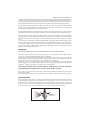
Questions? Call toll free: 888-783-2612
Your Earlex SprayStation 5500 comes equipped with a Viscosity Cup (26), which will help you determine the thickness
of the paint. To test a liquids viscosity, dip the viscosity cup into the material and fill up to the top, lift free and time how
long it takes for the paint to empty the viscosity cup. Stop when the continuous flow ends from the bottom of the cup.
The time determines the material viscosity and the need for the paint to be thinned before being sprayed (Fig.1).
TM
If the paint requires thinning, start with a 10% dilution of the paint. To do this, fill a quart container with the required
paint. The viscosity cup supplied with the unit holds 1/10 of a quart. Block the hole in the viscosity cup and fill up with
the required thinners. Add the thinners to the paint and stir well.
If the paint requires further thinning, dilute the paint by another 5% (5% will be equal to half a viscosity cup) with the
required thinners and measure the viscosity. If the paint is not at its recommended viscosity, repeat the above step.
Follow the manufacturer’s guide for thinning in conjunction with a spray gun. If in doubt please contact the manufacturer
of the paint. The viscosity cup will help you determine the correct thickness of the paint. Paint is “thinned” by adding
the substance which the paint is based upon. If a water-based paint then water is added, if oil-based then mineral
spirit.
As some paints, wood preservatives and other sprayable materials contain particles that have differing qualities, please
ensure that, when filling the paint container of the spray gun, the paint is filtered through either a funnel with a filter on
it or through nylon tights or stockings. This will ensure that no large particles enter the paint container, so preventing
blockages and providing you with trouble-free spraying. Ensure that suitable ear protection, face mask, gloves and
goggles are worn at all times when spraying.
OPERATION
To put the unit together, place the top section with the handle on top of the turbine and secure.
Fill the paint container with the material to be sprayed. Take care not to overfill. Stir well. For a better finish always stir
coating. Use of a paint stirrer/mixer/paddle with a drill is reccommended.
Take the spray gun unit and with the Clamp Lever (22) turned fully anticlockwise, locate the spray gun unit into the
Paint Container (17). Rotate the paint container until the 2 pins locate into the recesses in the Yoke (23). Now turn the
Clamp Lever (22) clockwise to secure the container to the Lid (20). Do not over-tighten.
Place the motor unit onto a clean and level floor space, free from any loose debris, liquids or dust sheets that could
block the motor inlet. Uncoil the Air Hose (29) and attach it to the back of the spray gun and the other end to the Earlex
SprayStationTM 5500. Uncoil the supply cord from the base of the unit and plug in.
ALWAYS KEEP THE MOTOR UNIT AS FAR AWAY FROM THE SPRAYING AREA AS POSSIBLE TO PREVENT
PAINT CONTAMINATING THE MOTOR. MASK ANY AREA YOU DO NOT WISH TO SPRAY.
Once you have set up and are ready to spray, switch on the unit. No paint will be sprayed from the gun until the spray
gun Trigger (25) is pulled.
Before spraying objects we suggest you spend time practicing on cardboard or newspaper until you have got used to
SPRAY PATTERNS
The gun has 3 different spray patterns – Horizontal, Vertical and Round (Fig.2). The horizontal and vertical spray patterns
are recommended for large surfaces. The round spray is used for small objects or for areas - such as corners – that
are difficult to reach. To change the spray patterns simply rotate Air Cap (2) until it clicks into the positions as shown in
(Fig.2). The overall size of the selected spray pattern can be varied by turning Air Cap Ring (1). When viewed from the
front, rotate it anticlockwise to increase the pattern size, or clockwise to reduce the pattern size (Fig.8).
Fig.8
7
Questions? Call toll free: 888-783-2612
PAINT VOLUME
The volume of paint sprayed is easily adjustable (Fig.3). Completely close Fluid Adjusting Screw (12) by turning
clockwise as far as it will go. Whilst pulling the Trigger (25), begin turning the Fluid Adjusting Screw (12)
anticlockwise until the volume of paint you require is obtained. If the spray contains too much paint turn the Fluid
Adjusting Screw (12) clockwise to reduce it.
Once you have set the spray pattern and the paint volume, you are ready to spray.
TECHNIQUE
1. To obtain the best results always keep your spray gun level and spray equally from side-to-side or up-or-down
from the surface. Avoid spraying at an angle as this will lead to runs on the surface (Figs.5-7).
2. Let your arm control the side-to-side movement rather than your wrist as this will aid even paint distribution over
the whole area.
3. Do not tip the spray gun more than a 45˚ angle when the motor is switched OFF.
FLUID TIPS AND NEEDLES
Paints, varnishes, wood treatments, etc, are manufactured using a variety of materials and have widely different
viscosities. You may find that the 0.08” (2.0mm) dia fluid tip and needle supplied with this spray gun does not enable
you to spray your particular choice of finish exactly as you would like. In such cases a change of fluid tip and needle
size will probably solve this problem. In general, thicker, more viscose materials are best sprayed through a larger
fluid tip to give best coverage. Thinner, less viscose materials are best sprayed through a smaller fluid tip.
To allow for these variations fluid tip and needle sets are available as optional extras in 0.04” 1.0mm) dia, 0.06”
(1.5mm) dia and 0.10” (2.5mm) dia (See page 6).
HELPFUL HINTS
1. Evenly control the speed of movement of the spray gun. A fast speed will give a thin coat and a slow speed will
give a heavy coat.
2. Only apply one coat at a time. If a further coat is required follow the paint manufacturer’s instructions for drying
times.
3. If spraying small areas or objects keep the Fluid Adjusting Screw (12) setting low as this will avoid excessive use
of paints and will minimise overspray.
4. When spraying large areas or objects, it is best to use a criss-cross pattern, either from left-to-right then up-ordown or vice-versa. This will ensure maximum coverage. Let go of Trigger (25) at the end of each spray movement
to avoid excessive paint and drips (Fig.4).
5. Avoid stopping and starting when spraying as this can lead to too much or not enough material on a surface.
6. To ensure edges are covered, commence spraying just to the side of area being sprayed.
7. CLEAN SPRAY GUN AFTER EVERY USE (SEE CLEANING INSTRUCTIONS).
CLEANING INSTRUCTIONS
THE SPRAY GUN SHOULD BE THOROUGHLY CLEANED AND THE GLAND WASHERS LUBRICATED,
IMMEDIATELY AFTER EACH USE. IF THE PAINT DRIES INSIDE THE GUN CLEANING WILL BE MUCH MORE
DIFFICULT AND MAY RENDER THE GUN INOPERABLE. THIS IS NOT COVERED BY THE WARRANTY.
Flush out the residue paint from the spray gun, as follows:
• Remove the Paint Container (17) from the spray gun.
• Pour any residual paint into its original container for future use.
• Use a cloth soaked in thinners to wipe out excess paint from the container, the underside of the Lid (20) and the
Gasket (19).
• Pour a small quantity of clean thinners into the container, refit the container to the spray gun and shake the gun
lightly.
• Now spray all of the thinners through the gun.
• Repeat this each time using clean thinners until there is no trace of paint in the thinners being sprayed.
To thoroughly clean the remainder of the spray gun, remove all working parts as per the exploded parts view on page
4 as follows:
• Loosen and remove Air Cap Ring (1), Air Cap (2) and Air Distributor Plate (3).
• Unscrew Adjusting Screw (12) and pull out Fluid Needle (9) and Spring (11).
• Using Spanner (27) supplied remove Fluid Tip (4) and Fluid Tip Seal (5).
8
Questions? Call toll free: 888-783-2612
After cleaning your spray gun and before fitting the needle, dip the tip into some petroleum jelly which will lubricate
Gland Washers (16) as the Needle (9) is inserted. The external surfaces of the spray gun can be wiped clean with a
cloth soaked in thinners.
PERIODIC MAINTENANCE
Gland Washers (16) prevent leakage of air pass the needle. This leakage reduces the performance of the spray gun
and must, therefore, be kept to a minimum. After a period of use the gland washers will wear. This is normal and can
be compensated by gradual adjustment of the Gland Nut (15).
Periodically check to ensure the Gland Nut (15) is not loose. DO NOT OVER-TIGHTEN as this will increase wear of
the washers. When necessary just tighten the nut lightly using the special Spanner (27) provided.
By tightening the nut, the inside diameter of gland washers reduce thereby closing any small gap that may have
occurred between the needle and gland washers, therefore, eliminating leakage.
TURBINE UNIT
The turbine unit only requires minimal maintenance:
• Ensure its Filter (28) element is kept clean at all times.
This is the filter underneath the main body of the turbine. Disconnect the unit from the power supply, turn on side
and remove foam material. This can be washed out if necessary and replaced when dry. From time to time this
filter will need replacing (Part No. L0058).
• The turbine bearings are sealed and lubricated for life. There is no maintenance or adjustment required.
• Clean the turbine and hose unit with a damp cloth after use.
• The hose is stowed by coiling it between the motor housing and hose cover.
• The supply cord is stowed by wrapping around the base of the unit and locating the plug in the space at the back
of the unit.
TROUBLESHOOTING
PROBLEM
CAUSE
ACTION REQUIRED
The paint runs on the Paint too diluted
item being sprayed
Paint volume too high
Add undiluted material
Reduce the paint flow by turning Fluid Adjusting
Screw (12) clockwise
Moving too slowly
Increase speed of application
Gun trigger held for too long
Paint is thin or
irregular
Release Trigger (25) earlier
Gun too close
Increase the distance between gun and work-piece
Paint too diluted
Add undiluted material
Paint volume too low
Increase the paint flow by turning Fluid Adjusting
Screw (12) anticlockwise
Moving too fast
Reduce speed of application
Gun clogged
No paint being
produced
Clean the gun
Gun too far away
Reduce the distance between gun and work-piece
Paint too thick
Add thinners
Gun clogged
Clean the gun
Pick-up tube clogged
Clean Pick-Up Tube (24)
Air hose split
Replace Air Hose (29)
Grainy paint
Filter the paint
Container almost empty
Refill Paint Container (17)
Gun at an angle
Ensure Pick-Up Tube (24) is angled towards paint
Air intake blocked
Check no paper or loose debris can block the air
intake underneath the unit. Replace Filter (28) if
necessary (Part No. L0058).
9