1
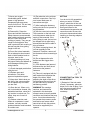
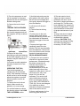
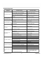
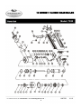
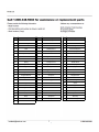
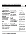
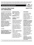
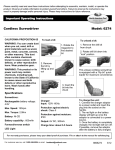
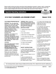
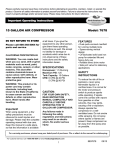
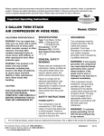
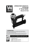
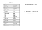
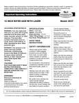
18 GAUGE 1-1/4 INCH BRAD NAILER CALIFORNIA PROPOSITION 65 WARNING: You can create dust when you cut, sand, drill or grind materials such as wood, paint, metal, concrete, cement, or other masonry. This dust often contains chemicals known to cause cancer, birth defects, or other reproductive harm. Wear protective gear. WARNING: This product or its power cord may contain chemicals, including lead, known to the State of California to cause cancer and birth defects or other reproductive harm. Wash hands after handling. Important! When using equipment, a few safety precautions must be observed to avoid injuries and damage. Please read the complete operating manual with due care. Keep this manual in a safe place, so that the information is available at all times. If you give the equipment to any other person, give them these operating instructions as well. We accept no liability for damage or accidents which arise due to non-observance of these instructions and the safety information herein. SPECIFICATIONS Operation Pressure: 60-100 PSI Magazine Capacity: 100 Piece Fastener Length: 3/8 - 1-1/4 in. Nail Size: 18 Gauge Air Inlet: 1/4” NPT Air Consumption: 1.6 CFM CAUTION: FOR YOUR OWN SAFETY, READ INSTRUCTION MANUAL COMPLETELY AND CAREFULLY BEFORE OPERATING THIS BRAD NAILER. Any failures made in following the safety regulations and instructions may result in an electric shock, fire, and/or serious injury. For customer service, call 1-800-348-5004 or email [email protected] Model: 7552 SAFETY INSTRUCTIONS 1) Read and understand tool labels and the manual. Failure to follow warnings, dangers, and precautions could result in death or serious injury. 2) Keep work area clean. Cluttered areas invite injuries. 3) Don’t allow children at the work area. Do not let them handle the tool. 4) Do not operate the tool if under the influence of alcohol or drugs. Read warning labels on prescriptions to determine if your judgment or reflexes are impaired while taking drugs. If there is any doubt, do not attempt to operate. 5) Use safety glasses. Safety glasses should conform to ANSI Z87.1 specifications. Before operating, wear safety glasses against flying debris from the front and side. Safety glasses should be worn when loading, operating, unloading, or servicing this tool. 6) Use ear protection. The working area may be exposed to high noise levels that can lead to hearing damaged. 8807552 01/13 7) Never use oxygen combustible gases, bottled gases or high pressure compressed gas as a power source for this tool. The tool may explode and cause serious injury. 16) Pay attention to the air hose and their connections. Don’t trip over hoses. Make sure all connections are tight. 8) Dress safely. Protective gloves and nonskid footwear or safety shoes are recommended when working with and operating this tool. Don’t wear loose clothing or jewelry. They can get caught in moving parts. Also, wear a protective hair covering to prevent long hair from getting caught in the tool. 18) Use the correct air connector. The connector on the tool must not hold pressure when the air supply is disconnected. If the wrong fitting is used, the tool can be charged with air after being disconnected and still be able to drive a fastener. 9) Do not fire to hard materials. Do not attempt to shoot toward hard or brittle material such as concrete, steel, or tile. 10) When operating tool, keep the proper footing and balance to avoid damage resulting from losing balance. 11) Check damaged parts before using the tool. 12) Replace parts and accessories. Only allow approved replacement parts. 13) Keep alert. Watch what you are doing. Use common sense. Do not operate any tool when you are tired. 14) Store the tool. When not in use, tool should be cleaned, fully assembled and then, stored in a dry location to reduce rust. For safety, keep out of reach of children. 15) Outdoor extension cord. When air compressor is used outdoors, use only rounded jackets extension cords intended for outdoor use. [email protected] 17) After loading the fasteners, never point the tool at yourself or any bystanders. SETTING Your air tool is fully assembled when you receive it. Before using it, attach the air line and desired air system accessories. See figure below for the recommended accessories and connection order. Be sure the air hose is depressurized when installing or removing adapters to the air line. 19) When connecting the air, the tool can possibly fire the fasteners. Therefore, remove all the fasteners before connecting to the air. 20) Do not depress the safe bracket and the trigger when loading. 21) If the fasteners are jammed, disconnect the tool from the air and remove the jammed fasteners. 22) This tool is equipped with the safe bracket that can adjust the depth of the driver. When adjusting the depth of the driver, first disconnect the tool from the air and rotate nut by thumb to satisfactory position. WARNING The warnings, cautions, and instructions explained in this instruction manual cannot cover all possible conditions and situations that may occur. It must be understood by the operator that common sense and caution are factors which cannot be built into this product, but must be supplied by the operator. 2 CONNECTING THE TOOL TO AN AIR SUPPLY 1) Determine if the tool needs oil and, if necessary, place two drops of oil in the air plug. If you are using an automatic in-line oiler, check and add oil if necessary. 2) Turn the compressor on and set the regulator to the proper pressure for the size and type of fasteners being used. 3) Connect the tool to the air supply. LOADING THE FASTENERS 1) Depress the lock to release the movable magazine and pull the magazine out fully as shown below. 2) Place a full clip of the specified type and size fasteners on the fixed magazine, up to 100 fasteners may be loaded in the magazine. 3) Push the movable magazine assembly forward until it was locked. OPERATING THE TOOL Test the driving depth in a sample piece of wood before using. If the fasteners are being driven too far or not far enough, adjust the regulator to provide less air pressure or more air pressure. 1) Connect the tool to the air supply. Make sure the air pressure is in correct range. 2) Load the fastener as above the direction given in the LOAD THE FASTENERS section. [email protected] 3) Hold the body and press the drive guide to the work surface. Be sure the tool is straight and then gently depress the trigger to drive the fastener. 4) Lift the tool off the work surface. 5) The tool has two driving modes. § Put the nose on the work surface, lightly push the tool towards the working surface until the safe bracket is depressed. Depress the trigger to drive the fastener. § Depress the trigger, then repeatedly impact the safe bracket. The tool can repeatedly drive the fasteners. The tool will drive one fastener when the safe bracket is impacted one time. REGULAR MAINTENANCE 1) Frequent, but not excessive, lubrication is required for best performance. Oil added through the airline connection will lubricate internal parts. An automatic airline oiler is recommended but oil may be added manually before every operation or after about 1 hour of continuous use. Only a few drops of oil at a time are necessary. Too much oil will collect inside the tool and be blown out during the exhaust cycle. ONLY USE PNEUMATIC TOOL OIL. Do not use detergent oil or additives as these lubricants will cause accelerated wear to the seal in the tool. 2) Use a small amount of oil on all moving parts and pivots. 3 3) Dirt and water in the air supply are major causes of pneumatic tool wear. Use a filter/oiler for better performance and longer life. The filter must have adequate flow capacity for the specific application. Consult the manufacturer’s instructions for proper maintenance of your filter. 4) Keep tools clean for better and safer performance. Use nonflammable cleaning solutions (CAUTION: Such solutions may damage O-Ring and other tool parts) only if necessary. DO NOT SOAK. Symptom Possible Cause(s) Corrective Action O-Ring in trigger valve are damaged. Check and replace O-Ring Trigger Valve head are damaged. Check and replace trigger valve head. Trigger Valve stem, seal, or O-Ring are damaged. Check and replace trigger valve stem, seal, or O-Ring Damaged piston O-Ring or bumper Check and replace O-Ring or bumper Screw Loose Tighten screws Damaged Seal Check and replace seal Worn bumper Replace bumper Air pressure is too high Adjust air pressure Insufficient oil Lubricate as instructed insufficient air supply Check air supply Broken spring in cylinder cap Exhaust port in cylinder cap is blocked Worn bumper or damaged spring (57) Dirt in front plate Replace spring Replace damaged internal parts Replace bumper or pusher spring clean drive channel of front plate Tool skips a fastener Inadequate airflow to tool Worn or dry O-Ring on piston Damaged O-Ring on trigger valve Cylinder cap seal leaking Joint guider is worn. Fasteners are jammed Fasteners are wrong size or damaged Magazine or front plate screws are loose Blade in piston assembly is damaged Worn blade in piston assembly Lack of power check hose and compressor fittings Replace O-Ring or lubricate Replace O-Ring Replace Seal Replace joint guider Use the recommended and undamaged fasteners Tighten screws Replace piston assembly Replace piston assembly Adjust to adequate air pressure Check cylinder cap spring for broken coils or reduced length. Check if exhaust port of cylinder cap is restricted Air leaking at Trigger Air leaking between body and drive guide Air leaking between body and cylinder cap Blade driving fastener too deeply Runs slowly or has power loss Tool will not drive down tight Slow cycling and loss of power [email protected] 4 North American Tool Industries (NATI) makes every effort to ensure that this product meets high quality and durability standards. NAT warrants to the original retail consumer a 1-year limited warranty from the date the product was purchased at retail and each product is free from defects in materials. Warranty does not apply to defects due directly or indirectly to misuse, abuse, negligence, or accidents, repairs or alterations, or a lack of maintenance. NATI shall in no event be liable for death, injuries to persons or property, or for incidental, special, or consequential damages arising from the use of our products. To receive service under warranty, the original manufacturer part must be returned for examination by an authorized service center. Shipping and handling charges may apply. If a defect is found, NATI will either repair or replace the product at its discretion. [email protected] 5 18 GAUGE 1-1/4 INCH BRAD NAILER Model: 7552 For customer service, call 1-800-348-5004 or email [email protected] 6 8907552 01/13 NO Description NO Description NO Description 01 Screw 25 Spring 48 Drive Guide 02 Bushing 26 Safe Bracket A 49 Rail 03 Exhaust Cover 27 Safe Bracket B 50 Spring Pin 04 Seal 28 Safe Bracket C 51 Movable Magazine 05 Screw 29 Spring Pin 52 Spring 06 Cylinder Cap 30 Seal 53 Pin 07 Gasket 31 Trigger Valve Head 54 Lock 08 Seal 32 Spring 55 Locking Washer 09 Spring 33 O Ring 5.5x1.5 56 Feeder Shoe 10 O Ring 15.75x2 34 Trigger Valve Stem 57 Spring 11 O Ring 38.8x3 35 O Ring 15x1.9 58 Spring Seat 12 Valve 36 Trigger Valve Guide 59 Screw 13 O Ring 33.5x3.5 37 Trigger Spring 60 Stopped Plate 14 Stopped Washer 38 Spring Pin 61 Stopped Piece 15 O Ring 50.5x2.5 39 Pin 62 Screw 16 Collar 40 Trigger 63 Fixed Magazine 17 O Ring 28.3x3 41 Washer 64 Screw 18 Piston Assembly 42 Screw 65 Support 19 O Ring 36.3x2.5 43 Plate 66 Nut 20 Cylinder 44 Front Plate 67 Soft Grip Sleeve 21 Bumper 45 Latch Assembly 68 Ring 40.2x2.3 22 Body 46 Spring Pin 69 End Cap 23 Joint Guide 47 Spring Pin 70 Air Plug 24 Safe Guider [email protected] 7