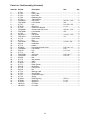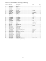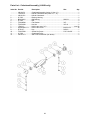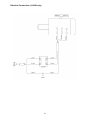
1
This .pdf document is bookmarked
Operating Instructions and Parts Manual
8-inch Woodworking Jointer
Models JJ-8CS and JJ-8HH
Model JJ-8CS
Model JJ-8HH
WALTER MEIER (Manufacturing) Inc.
427 New Sanford Road
LaVergne, Tennessee 37086
Ph.: 800-274-6848
www.waltermeier.com
Part No. M-708458
Revision H1 05/2013
Copyright © 2013 Walter Meier (Manufacturing) Inc.
Warranty and Service
Walter Meier (Manufacturing) Inc., warrants every product it sells. If one of our tools needs service or repair, one of
our Authorized Service Centers located throughout the United States can give you quick service. In most cases, any
of these Walter Meier Authorized Service Centers can authorize warranty repair, assist you in obtaining parts, or
perform routine maintenance and major repair on your JET® tools. For the name of an Authorized Service Center in
your area call 1-800-274-6848.
MORE INFORMATION
Walter Meier is consistently adding new products to the line. For complete, up-to-date product information, check with
your local Walter Meier distributor, or visit waltermeier.com.
WARRANTY
JET products carry a limited warranty which varies in duration based upon the product (MW = Metalworking, WW =
Woodworking).
WHAT IS COVERED?
This warranty covers any defects in workmanship or materials subject to the exceptions stated below. Cutting tools,
abrasives and other consumables are excluded from warranty coverage.
WHO IS COVERED?
This warranty covers only the initial purchaser of the product.
WHAT IS THE PERIOD OF COVERAGE?
The general JET warranty lasts for the time period specified in the product literature of each product.
WHAT IS NOT COVERED?
Five Year Warranties do not cover woodworking (WW) products used for commercial, industrial or educational
purposes. Woodworking products with Five Year Warranties that are used for commercial, industrial or education
purposes revert to a One Year Warranty. This warranty does not cover defects due directly or indirectly to misuse,
abuse, negligence or accidents, normal wear-and-tear, improper repair or alterations, or lack of maintenance.
HOW TO GET SERVICE
The product or part must be returned for examination, postage prepaid, to a location designated by us. For the name
of the location nearest you, please call 1-800-274-6848.
You must provide proof of initial purchase date and an explanation of the complaint must accompany the
merchandise. If our inspection discloses a defect, we will repair or replace the product, or refund the purchase price,
at our option. We will return the repaired product or replacement at our expense unless it is determined by us that
there is no defect, or that the defect resulted from causes not within the scope of our warranty in which case we will,
at your direction, dispose of or return the product. In the event you choose to have the product returned, you will be
responsible for the shipping and handling costs of the return.
HOW STATE LAW APPLIES
This warranty gives you specific legal rights; you may also have other rights which vary from state to state.
LIMITATIONS ON THIS WARRANTY
WALTER MEIER (MANUFACTURING) INC., LIMITS ALL IMPLIED WARRANTIES TO THE PERIOD OF THE
LIMITED WARRANTY FOR EACH PRODUCT. EXCEPT AS STATED HEREIN, ANY IMPLIED WARRANTIES OR
MERCHANTABILITY AND FITNESS ARE EXCLUDED. SOME STATES DO NOT ALLOW LIMITATIONS ON HOW
LONG THE IMPLIED WARRANTY LASTS, SO THE ABOVE LIMITATION MAY NOT APPLY TO YOU.
WALTER MEIER SHALL IN NO EVENT BE LIABLE FOR DEATH, INJURIES TO PERSONS OR PROPERTY, OR
FOR INCIDENTAL, CONTINGENT, SPECIAL, OR CONSEQUENTIAL DAMAGES ARISING FROM THE USE OF
OUR PRODUCTS. SOME STATES DO NOT ALLOW THE EXCLUSION OR LIMITATION OF INCIDENTAL OR
CONSEQUENTIAL DAMAGES, SO THE ABOVE LIMITATION OR EXCLUSION MAY NOT APPLY TO YOU.
Walter Meier sells through distributors only. The specifications in Walter Meier catalogs are given as general
information and are not binding. Members of Walter Meier reserve the right to effect at any time, without prior notice,
those alterations to parts, fittings, and accessory equipment which they may deem necessary for any reason
whatsoever. JET® branded products are not sold in Canada by Walter Meier.
2
Table of Contents
Warranty and Service .............................................................................................................................. 2 Table of Contents .................................................................................................................................... 3 Warning................................................................................................................................................... 4 Introduction ............................................................................................................................................. 5 Levers and Controls ................................................................................................................................ 6 Specifications .......................................................................................................................................... 6 Unpacking and Cleanup .......................................................................................................................... 7 Unpacking and Cleanup ....................................................................................................................... 7 Installing Bed to Stand ......................................................................................................................... 8 Installing Pedestal Switch (JJ-8HH only) .............................................................................................. 8 Installing Handwheels .......................................................................................................................... 9 Assembling Knife-Setting Gauge (JJ-8CS only) .................................................................................... 9 Installing V-Belts .................................................................................................................................. 9 Installing Cutterhead Guard................................................................................................................ 10 Installing Access Door ........................................................................................................................ 10 Installing Dust Chute .......................................................................................................................... 10 Electrical Connections........................................................................................................................ 10 Extension Cords................................................................................................................................. 11 Adjustments .......................................................................................................................................... 11 90° Fence Adjustment ........................................................................................................................ 11 45° Fence Adjustment ........................................................................................................................ 12 Leveling Outfeed Table to Cutterhead Knives .................................................................................... 12 Removing and Replacing Knives (JJ-8CS only) .................................................................................. 14 Replacing or Rotating Knife Inserts (JJ-8HH only) .............................................................................. 14 Gib Adjustment .................................................................................................................................. 15 Operation .............................................................................................................................................. 15 Jointing Warped Material.................................................................................................................... 16 Direction of Grain ............................................................................................................................... 16 Bevel Cut ........................................................................................................................................... 16 Taper Cut........................................................................................................................................... 17 Rabbet Cut ........................................................................................................................................ 17 Maintenance.......................................................................................................................................... 18 Lubrication ......................................................................................................................................... 18 Blade Care......................................................................................................................................... 18 Sharpening the Knives (JJ-8CS only) ................................................................................................. 18 Cutterhead Removal .......................................................................................................................... 18 Replacement Parts ................................................................................................................................ 20 Fence Assembly (all models) ............................................................................................................. 21 Parts List – Fence Assembly (all models) ........................................................................................... 21 Bed Assembly (all models) ................................................................................................................. 22 Parts List – Bed Assembly (all models)............................................................................................... 23 Stand and Motor Assembly (JJ-8CS only) .......................................................................................... 24 Parts List – Stand and Motor Assembly (JJ-8CS only) ........................................................................ 25 Stand and Motor Assembly (JJ-8HH only) .......................................................................................... 26 Parts List – Stand and Motor Assembly (JJ-8HH only) ........................................................................ 27 Parts List – Cutterhead Assembly (JJ-8CS only)................................................................................. 28 Parts List – Cutterhead Assembly (JJ-8HH only) ................................................................................ 29 Electrical Connections (JJ-8CS only).................................................................................................. 30 Electrical Connections (JJ-8HH only).................................................................................................. 31 3
Warning
1. Read and understand the entire owners manual before attempting assembly or operation.
2. Read and understand the warnings posted on the machine and in this manual. Failure to comply with
all of these warnings may cause serious injury.
3. Replace the warning labels if they become obscured or removed.
4. This jointer is designed and intended for use by properly trained and experienced personnel only. If
you are not familiar with the proper and safe operation of a jointer, do not use until proper training and
knowledge have been obtained.
5. Do not use this jointer for other than its intended use. If used for other purposes, Walter Meier
(Manufacturing) Inc., disclaims any real or implied warranty and holds itself harmless from any injury
that may result from that use.
6. Always wear approved safety glasses/face shields while using this jointer. Everyday eyeglasses only
have impact resistant lenses; they are not safety glasses.
7. Before operating this jointer, remove tie, rings, watches and other jewelry, and roll sleeves up past
the elbows. Remove all loose clothing and confine long hair. Non-slip footwear or anti-skid floor strips
are recommended. Do not wear gloves.
8. Wear ear protectors (plugs or muffs) during extended periods of operation.
9. Some dust created by power sanding, sawing, grinding, drilling and other construction activities
contains chemicals known to cause cancer, birth defects or other reproductive harm. Some examples
of these chemicals are:
•
Lead from lead based paint.
•
•
Crystalline silica from bricks, cement and other masonry products.
Arsenic and chromium from chemically treated lumber.
Your risk of exposure varies, depending on how often you do this type of work. To reduce your
exposure to these chemicals, work in a well-ventilated area and work with approved safety
equipment, such as face or dust masks that are specifically designed to filter out microscopic
particles.
10. Do not operate this machine while tired or under the influence of drugs, alcohol or any medication.
11. Make certain the switch is in the OFF position before connecting the machine to the power supply.
12. Make certain the machine is properly grounded.
13. Make all machine adjustments or maintenance with the machine unplugged from the power source.
14. Remove adjusting keys and wrenches. Form a habit of checking to see that keys and adjusting
wrenches are removed from the machine before turning it on.
15. Keep safety guards in place at all times when the machine is in use. If removed for maintenance
purposes, use extreme caution and replace the guards immediately.
16. Make sure the jointer is firmly secured to the stand or a bench before use.
17. Check damaged parts. Before further use of the machine, a guard or other part that is damaged
should be carefully checked to determine that it will operate properly and perform its intended
function. Check for alignment of moving parts, binding of moving parts, breakage of parts, mounting
and any other conditions that may affect its operation. A guard or other part that is damaged should
be properly repaired or replaced.
18. Provide for adequate space surrounding work area and non-glare, overhead lighting.
19. Keep the floor around the machine clean and free of scrap material, oil and grease.
20. Keep visitors a safe distance from the work area. Keep children away.
4
21. Make your workshop child proof with padlocks, master switches or by removing starter keys.
22. Give your work undivided attention. Looking around, carrying on a conversation and “horse-play” are
careless acts that can result in serious injury.
23. Maintain a balanced stance at all times so that you do not fall or lean against the knives or other
moving parts. Do not overreach or use excessive force to perform any machine operation.
24. Use the right tool at the correct speed and feed rate. Do not force a tool or attachment to do a job for
which it was not designed. The right tool will do the job better and safer.
25. Use recommended accessories; improper accessories may be hazardous.
26. Maintain tools with care. Keep knives sharp and clean for the best and safest performance. Follow
instructions for lubricating and changing accessories.
27. Turn off the machine and disconnect from power before cleaning. Use a brush or compressed air to
remove chips or debris — do not use your hands.
28. Do not stand on the machine. Serious injury could occur if the machine tips over.
29. Never leave the machine running unattended. Turn the power off and do not leave the machine until it
comes to a complete stop.
30. Remove loose items and unnecessary work pieces from the area before starting the machine.
Familiarize yourself with the following safety notices used in this manual:
This means that if precautions are not heeded, it may result in minor injury and/or
possible machine damage.
This means that if precautions are not heeded, it may result in serious injury or possibly
even death.
Introduction
This manual is provided by Walter Meier (Manufacturing) Inc., covering the safe operation and
maintenance procedures for the JET Model JJ-8CS and JJ-8HH Woodworking Jointers. This manual
contains instructions on installation, safety precautions, general operating procedures, maintenance
instructions and parts breakdown. This machine has been designed and constructed to provide years of
trouble free operation if used in accordance with instructions set forth in this manual. If there are any
questions or comments, please contact either your local supplier or Walter Meier. Walter Meier can also
be reached at our web site: www.waltermeier.com.
5
Levers and Controls
1. Handwheel for Outfeed Table
2. Outfeed Table
3. Fence
4. Fence Adjustment Handle
5. Cutter Guard
6. Infeed Table
7. Handwheel for Infeed Table
8. On/Off Switch (Pedestal style on JJ-8HH)
9. Rabbeting Ledge
10. Table Lock Knob
11. Fence Tilt Lock Handle
12. Fence Control Handle
13. Belt Guard
14. Dust Chute
Specifications
Model
JJ-8CS
JJ-8HH
Stock Number – Bed and Stand Kit ................................708458K................................................ 708468K
Stock Number – Bed Assembly ..................................... 708458J................................................. 708468J
Stock Number Stand......................................................708458S................................................ 708460S
Cutting Capacity ....................................................... 8"W x 1/2"D........................................... 8"W x 1/2"D
Cutterhead Speed ...................................................... 5500 RPM..............................................5500 RPM
Number of Knives ......................................................................3....................................... 36 knife inserts
Rabbeting Capacity .............................................................. 1/2".........................................not applicable
Rabbet Ledge ........................................................3-1/8" x 8-3/4"........................................ 3-1/8" x 8-3/4"
Table Surface .......................................................9”W x 66-1/2”L....................................... 9”W x 66-1/2”L
Fence ...................................................................4”W x 38-1/2”L....................................... 4”W x 38-1/2”L
Knife Size .................................................. 8”L x 11/16”W x 1/8”T......................... 0.59”L x 0.59”W x 0.10T
Fence Tilt ................................................................... 45ºL, 45ºR ............................................ 45ºL, 45ºR
Positive Stops...................................................... 45ºL, 90º, 45ºR...................................... 45ºL, 90º, 45ºR
Motor................................................ 2HP, 1Ph, 60Hz, 230V only.................... 2HP, 1Ph, 60Hz, 230V only
Net Weight, Jointer and Stand (approx.) ......................... 400 lbs.................................................... 411 lbs
Shipping Weight, Jointer and Stand ................................ 495 lbs.................................................... 505 lbs
The above specifications were current at the time this manual was published, but because of our policy of
continuous improvement, Walter Meier (Manufacturing) Inc., reserves the right to change specifications at
any time and without prior notice, without incurring obligations.
6
Unpacking and Cleanup
Contents of Shipping Cartons
Note: Unit shipped in two cartons.
Stand Carton
1 Stand with Motor
1 Stand Door
1 Dust Chute with Mounting Hardware
1 Pedestal Switch with Mounting Hardware
(JJ-8HH only)
Main Unit Carton
1 Bed Assembly
1 Fence Assembly
1 Cutterhead Guard
1 Belt Guard
2 V-Belts
2 Handwheels with handle
1 Fence Handle
3 Mounting Bolts
3 3/8" Lock Washers
1 Operating Instructions and Parts Manual
1 Warranty Card
Tools Included with JJ-8CS
1 12/14mm Open End Wrench
1 8/10mm Open End Wrench
3 Hex Wrenches (3, 4 and 5 mm)
1 Knife Gauge Assembly
Tools included with JJ-8HH:
1 12/14mm Open End Wrench
1 8/10mm Open End Wrench
4 Hex Wrenches (3, 4, 5, 6 mm)
2 Star Point Screwdrivers
5 Knife Inserts
10 Knife Insert Screws
Tools Required for Assembly:
#1 Cross Point Screwdriver
6-8” Adjustable Wrench or 17 & 19mm Wrench
Unpacking and Cleanup
1. Carefully finish removing all contents from
both shipping cartons. Compare contents of
the shipping cartons with the list of contents
above. Place parts on a protected surface.
2. Set packing material and shipping cartons to
the side. Do not discard until machine has
been set up and is running properly.
3. Clean all rust protected surfaces (bed,
fence, etc.) with kerosene or diesel oil. Do
not use gasoline, paint thinner, mineral
spirits, etc. These may damage painted
surfaces.
7
Cutterhead
knives
dangerously sharp!
extreme caution when cleaning.
are
Use
4. Apply a thin layer of paste wax to the bright
surfaces of the fence and tables to prevent
rust.
Installing Bed to Stand
1. Use an assistant or hoist mechanism to
place bed assembly on top of stand. Be
sure identification label on the bed faces the
same direction as the label on the stand
(Fig. 1).
Figure 1
2. Line up two holes in top of stand with holes
in bed assembly by viewing through access
door in stand.
3. Attach bed assembly to stand with two 3/8"
lock bolts and lock washers (Fig. 2). Hand
tighten only at this time.
4. Line up third hole in stand with hole in bed
assembly by viewing through dust chute.
5. Install third 3/8" lock bolt and lock washer
through dust chute to secure bed to stand.
Figure 2
6. Tighten all three mounting bolts with 14mm
wrench.
Installing Pedestal Switch (JJ-8HH
only)
Referring to Figure 3:
1. The switch may be installed in either high
position or low position to suit the operator.
Slide the connection plug through the
opening (A) and secure the pedestal switch
using two 5/16”x3” screws (C) and 5/16” flat
washers (B).
2. Connect the plug from the pedestal switch
to the motor plug inside the cabinet.
Figure 3
8
Installing Handwheels
1. Remove protective tape from shaft, and
remove screw and washer.
2. Press handwheel (A, Fig. 4) onto shaft,
aligning the keyway with the key.
If
necessary, use a hammer with a block of
wood to tap the handwheel completely onto
the shaft.
3. Re-install screw and washer (B, Fig. 4).
4. Mount handle (C, Fig. 4) onto handwheel.
Figure 4
Assembling Knife-Setting Gauge (JJ8CS only)
Place the two bases (A, Fig. 5) onto each end of
the bar (B, Fig. 5). Snap the four E-rings (C,
Fig. 4) into the grooves on the bar as shown,
one E-ring on each side of a base.
Installing V-Belts
1. Disconnect the machine from the power
source, unplug.
Figure 5
2. Remove the lock knob (A, Fig. 6) and belt
guard (B, Fig. 6).
3. Place v-belts onto cutterhead pulley grooves
and through opening in stand.
4. Pull v-belts down and place onto motor
pulley (Fig. 7). If necessary, loosen the
mounting screws (A, Fig. 7) and slightly lift
motor. Re-tighten the screws when belt is
placed.
5. Check to make sure that motor pulley and
cutterhead pulley are vertically aligned and
the v-belt does not contact the sides of the
opening in the base. If the pulleys are not
aligned, loosen the screws (A, Fig. 7) on the
motor base and slide the motor until the belt
is aligned. Re-tighten screws.
Figure 6
6. The v-belt is properly tensioned when finger
pressure on the belt half way between the
two pulleys causes 1/2" deflection. If the belt
is too loose, loosen the lower screws (B,
Fig. 7) on the mounting plate and push
down on the plate. When belt tension is
correct, re-tighten screws.
7. After two hours of operation, check belt
tension again. Re-tension if necessary.
8. Re-install belt guard and lock knob.
Figure 7
9
Installing Cutterhead Guard
Orient guard (Fig. 8) in proper position and
insert post into hole in table. Tighten lock screw
(A, Fig. 8).
Installing Access Door
Install access door by placing bottom of panel
into access in stand and fastening by turning
latch (Fig. 9).
Figure 8
If the access door latch needs adjustment:
1. Remove the access door from the stand.
2. Loosen the hex lock nut (A, Fig. 9). Rotate
the latch a quarter turn clockwise to tighten
and counterclockwise to loosen.
3. Tighten the lock nut (A, Fig. 9).
4. Re-install the access door.
Figure 9
Installing Dust Chute
Attach the dust chute (Fig. 10) to the stand with
four screws and four flat washers, through the
pre-tapped holes in the stand.
Electrical Connections
Electrical connections must
be made by a qualified electrician in
compliance with all relevant codes. This
machine must be properly grounded to help
prevent electrical shock and possible fatal
injury.
Figure 10
Model JJ-8CS: Remove the cover of the switch
box (A, Fig. 11) and mount the box to the right
side of the stand using the two screws provided.
Insert the motor leads through the hole in the
stand as shown, and insert a grommet (B, Fig.
11).
Consult the wiring diagram inside the switch box
cover. The diagram is also on page 30 of this
manual.
Figure 11
10
The JJ-8CS and JJ-8HH jointers are rated at
230V, single phase only. Confirm that the
power at the source is compatible with the
jointer before inserting plug into the outlet. The
jointer is designed to be used with a plug and
outlet similar to that shown in Fig. 12.
Important: Make certain the receptacle in
question is properly grounded. If you are
not sure, have a registered electrician check
the receptacle.
Figure 12
Extension Cords
Recommended Extension Cord Gauges (AWG)
Make sure the rating of the extension cord is
suitable for the amperage listed on the
machine’s motor plate. An undersize cord will
cause a drop in line voltage resulting in loss of
power and overheating.
Extension Cord Length in Feet *
Amps
Use the chart in Figure 13 as a general guide in
choosing the correct size cord. If in doubt, use
the next heavier gauge. The smaller the gauge
number, the heavier the cord.
Adjustments
25
50
75
100
150
200
<5
16
16
16
14
12
12
5 to 8
16
16
14
12
10
NR
8 to 12
14
14
12
10
NR
NR
12 to 15
12
12
10
10
NR
NR
15 to 20
10
10
10
NR
NR
NR
21 to 30
10
NR
NR
NR
NR
NR
*based on limiting the line voltage drop to 5V at 150% of the
rated amperes.
NR: Not Recommended.
Figure 13
90° Fence Adjustment
Note: whenever making an adjustment to the
fence, lift the fence up slightly after releasing the
lock handle to avoid scratching the table.
1. Set infeed table to the same height as the
outfeed table.
2. Move the fence by releasing lock handle (A,
Fig. 14) and pushing the fence assembly
until it overlaps the tables.
3. Adjust the fence to a 90° angle by releasing
lock handle (B, Fig. 14), pulling up on
handle (C, Fig. 14), and re-tightening lock
handle (B, Fig. 14).
Figure 14
4. Place a combination square on the infeed
table. (Fig. 15)
5. If fence is not square to table, release lock
handle (B, Fig. 14), loosen nut (D, Fig. 14),
and turn bolt (E, Fig. 14) until fence is
square to table.
6. Tighten nut (D, Fig. 14) to retain the setting.
Tighten lock handle (B, Fig. 14).
Figure 15
11
45° Fence Adjustment
Note: Whenever making an adjustment to the
fence, lift the fence up slightly after releasing the
lock handle to avoid scratching the table.
1. Loosen lock handle (A, Fig. 16). Move the
stop plate (B, Fig. 16) out of the way and
position the fence at the 45° angle. Make
sure the fence sits against the stop bolt (C,
Fig. 16).
2. Place a combination square (D, Fig. 16) on
the fence and table to confirm a 45° setting.
Figure 16
3. To adjust, loosen lock nut (E, Fig. 16), turn
bolt (C, Fig. 16) until a 45° angle is
obtained, and tighten lock nut (E, Fig. 16).
Tighten lock handle (A, Fig. 16).
Leveling Outfeed Table to
Cutterhead Knives
Machine
should
be
disconnected from power source at this
time! Cutterhead blades are extremely sharp!
Use caution when hands are near the
cutterhead!
For most jointing operations, the surface of the
outfeed table must be level with the knife tips of
the cutterhead at their highest point of
revolution. The knife tips must project equally
from the cutterhead.
The outfeed table and cutterhead are adjusted
at the factory and should not require adjustment.
1. On the JJ-8CS Jointer, carefully number
each blade with a magic marker to make
them easier to differentiate.
2. Rotate the cutterhead by turning the
cutterhead pulley and determine the 12
o’clock position of knife number one (or a
knife insert on the JJ-8HH model). The 12
o’clock position is the highest point a blade
will reach in the cutting arc.
Figure 17
3. Loosen table lock screw (A, Fig. 17) and
raise the outfeed table to the height of blade
number one by turning handwheel (B, Fig.
17). Counter-clockwise will cause the
outfeed table to raise. Clockwise will cause
the outfeed table to lower.Set a straight
edge (C, Fig. 17) on the outfeed table and
across the cutterhead.
4. Position of the table and straight edge
should look like Figure 18. Use care when
handling the straight edge near the blades
so as not to damage them.
Figure 18
12
5. When the outfeed table and blade number
one (or knife insert) are the same height,
tighten table lock screw.
After the outfeed table has been set, the JJ8HH will need no further adjustments to the
cutterhead – skip steps 6 through 9 below.
The JJ-8CS must have its knives parallel
with the outfeed table. Proceed as follows:
6. Bring the straight edge forward to the front
of the outfeed table and confirm that blade
number one is at the same height at the
front of the table as it is at the back of the
table.
Figure 19
7. If blade is higher or lower at one point,
slightly loosen five screws (A, Fig. 19) by
turning clockwise as viewed from the infeed
table.
8. Place the knife setting gauge (B, Fig. 19) on
the cutterhead over the blade. Continue
loosening the five screws until the springs
push the knife up into contact with the
gauge. Alternately tighten the five screws to
hold each blade in place.
9. Repeat this process with blades two and
three. The outfeed table and cutterhead
knives are correctly adjusted when all three
blades are parallel to the outfeed table and
all three blades are set at the same height in
the cutterhead.
Figure 20
After the outfeed table has been set at the
correct height, do not change it except for
special operations or after replacing the knives.
If the outfeed table is set too high, a curved
finished surface results. (Fig. 20)
If the outfeed table is set too low, gouging
results at the end of the cut. (Fig. 21)
Figure 21
Figure 22 illustrates the outfeed table at the
correct height.
Figure 22
13
Removing and Replacing Knives (JJ8CS only)
Disconnect the machine from
the power source before making any
adjustment or repair. All knife lock bolts
must be firmly tightened or risk ejection of
the knife(s) and lock bar from the cutterhead!
Failure to comply may cause serious injury!
1. Disconnect machine from power source.
Figure 23
2. Remove blade guard by loosening lock
screw (A, Fig. 23) and lifting up on blade
guard. Caution: blades are sharp! Use
great care when hands are around blade
area!
3. Loosen the five lock screws (Fig. 24). Note:
Loosen screws by turning in a clockwise
direction as viewed from the infeed table.
Carefully remove the knife (A, Fig. 25), and
the lock bar with screws (B, Fig. 25).
Repeat for the other two blades.
4. Before assembly, clean all parts thoroughly
and clear cutterhead knife slots of any dust
or debris.
Figure 24
5. Insert knife into the cutterhead channel
making sure it faces the proper direction.
6. Insert lock bar and screws and tighten to
hold in place. Blades are set at the proper
height when the top of the blade is 1/16"
above the cutterhead.
7. Repeat for other two blades.
8. To set the knives to the outfeed table and to
the same height in the cutterhead, see
section titled “Leveling Outfeed Table to
Cutterhead Knives” found on page 12 of this
manual.
Figure 25
Replacing or Rotating Knife Inserts
(JJ-8HH only)
The knife inserts on the model JJ-8HH Jointer
are four-sided. When dull, simply remove each
insert, rotate it 90° for a fresh edge, and reinstall it.
Use the two provided star point screwdrivers to
remove the knife insert screw. See Figure 26.
Use one of the screwdrivers to help hold the
cutterhead in position, and the other to remove
the screw. It is advisable to rotate all inserts at
the same time to maintain consistent cutting.
However, if one or more knife inserts develops a
nick, rotate only those inserts that are affected.
Figure 26
14
Each knife insert has an etched reference mark
so that you can keep track of the rotations.
IMPORTANT: When removing or rotating
inserts, clean saw dust from the screw, the
insert, and the cutterhead platform. Dust
accumulation between these elements can
prevent the insert from seating properly, and
may affect the quality of the cut.
Before installing each screw, lightly coat the
screw threads with machine oil and wipe off any
excess.
Securely tighten each screw which holds the
knife inserts before operating the planer!
Make sure all knife insert
screws are tightened securely. Loose inserts
can be propelled at high speed from a
rotating cutterhead, causing injury.
Gib Adjustment
After a period of use, the gibs may become
loose and need adjusting:
1. Loosen three lock nuts (A, Fig. 27) and gib
lock screw (B, Fig. 27)
2. Tighten each set screw 1/4 turn starting at
the bottom and working up. If a 1/4 turn
does not remove all play, take another 1/4
turn. Repeat a 1/4 turn at a time for all three
set screws until play is removed.
Figure 27
3. Tighten lock screw (B, Fig. 27) and lock nuts
(A, Fig. 27).
Operation
Keep all guards in place and
in adjustment at all times during the cutting
procedure! Keep hands away from the
cutterhead! Do not pass hands directly over
the cutterhead! The use of push sticks
and/or handle pads are highly recommended
when using the jointer! Failure to comply
may cause serious injury!
Figure 28
Jointing cuts or edge jointing are made to
square an edge of a workpiece. The workpiece
is positioned on the jointer with the narrow edge
of the workpiece on the infeed table and the
major flat surface of the workpiece against the
fence (Fig. 28).
Planing cuts are similar. The major surface of
the workpiece is placed on the table with the
narrow edge of the workpiece against the fence
(Fig. 29).
Figure 29
15
For jointing and planing cuts pressure is directed
three ways; into the fence to ensure a square
cut, forward to advance the stock, and
downward to avoid chatter and vibration.
For jointing when the material is higher than the
fence, the left hand applies pressure into the
fence and down toward the table while the right
hand pushes forward from behind. Be sure to
keep the right hand high up on the material.
(Fig. 28)
For jointing material that is lower than the fence,
use push sticks to protect the hands. For
planing, use handle pads. (Fig. 29) Never
place the right hand on the trailing edge of
the material. Hand placement on the trailing
edge of the material may cause the hand to
come into contact with the blade.
Feed work from right to left at a steady,
moderate speed. If you feed the material too
slowly, the wood will burn in places. If you feed
the material too quickly, ridges will appear in the
finished surface.
Jointing Warped Material
If the work to be jointed is cupped or warped,
take light, repetitive cuts until the surface is flat.
Forcing the material flat against the table will still
leave a warped piece after the cuts have been
made.
Never joint any material
shorter than eight inches! The material may
tip into the jointer’s throat and be kicked
back! Avoid jointing thin material which
could become jammed under the fence or
blade guard! Failure to comply may cause
serious injury!
Direction of Grain
Feed the material with of the grain to avoid
tearout (Fig. 30). If the direction of the grain
changes somewhere in the board, try reducing
depth of cut and slow the feed speed down to
avoid tearout. If results still aren’t satisfactory,
turn the material around and try feeding through
the other way.
Figure 30
Bevel Cut
To cut a bevel, lock the fence at the desired
angle and run the material through, pressing the
work firmly against the fence and tables (Fig.
31). Several passes may be necessary for the
desired result.
Figure 31
16
Taper Cut
Taper cuts require the
removal of the cutterhead guard. Use
extreme caution when making taper cuts and
replace the guard immediately after
completion! Failure to comply may cause
serious injury!
One of the most useful jointer operations is
cutting an edge to a taper. This method can be
used on a wide variety of work; tapered legs of
furniture is a common example.
Instead of laying the piece down on the infeed
table, lower the forward end of the work onto the
outfeed table. Use caution, however, as the
piece will span the knives, and they will take a
“bite” from the work with a tendency to kick back
unless the piece is held firmly. Push the work
forward as in ordinary jointing. The effect is to
plane off all the stock in front of the knives to an
increasing depth, leaving a tapered surface.
The ridge left by the knives when starting the
taper may be removed by taking a very light cut
in the regular jointing procedure, with the infeed
table raised to its normal position.
Practice is required in this operation. Beginners
are advised to make trial cuts with scrap
material.
Rabbet Cut
Rabbeting requires the
removal of the cutterhead guard. Use
extreme caution when making rabbeting cuts
and replace the guard immediately after
completion! Failure to comply may cause
serious injury!
Note: Rabbet cuts are not applicable with the
Model JJ-8HH Jointer with helical head.
1. Adjust the fence so that the distance
between the end of the knives and fence is
equal to the width of the rabbet (Fig. 32).
Figure 32
2. Lower the infeed table an amount equal to
the depth of the rabbet. If the rabbet is quite
deep, it may be necessary to cut in two or
more passes.
3. In that event, the table is lowered an amount
equal to about half the depth of the rabbet
for the first pass, then lowered again to
proper depth to complete the cut.
17
7. Take the same amount of passes for all
three blades.
Maintenance
When the blades have been sharpened, if they
still are not cutting efficiently, trying to touch up
the blades further will only cause the formation
of a second beveled edge. When this starts to
happen, it is time to replace blades with another
set.
Lubrication
1. Use a good grade of light grease on the
steel adjusting screws located in the raising
and lowering mechanisms of the work
tables.
It is recommended to keep a second set of
blades on hand so that they may be installed
while the first set is being professionally
sharpened.
2. Occasionally, apply a few drops of light
machine oil to the gibs. This permits the
tables to slide freely.
3. The cutterhead ball bearings are lifetime
lubricated and need no further care.
Cutterhead Removal
Blade Care
Blades in the cutterhead are
sharp! Use extreme caution when handling
the removal of the cutterhead. Failure to
comply may cause serious injury!
Blades are extremely sharp!
Use caution when cleaning or changing.
Failure to comply may cause serious injury!
When gum and pitch collect on the blades,
carefully remove with a strong solvent. Failure
to remove gum and pitch build-up may result in
excessive friction and overheating.
The entire cutterhead assembly may be
removed for cleaning or for bearing and blade
replacement. Some woodworkers keep a spare
cutterhead with replacement blades should the
original cutterhead have to be repaired.
Sharpening the Knives (JJ-8CS only)
To remove the cutterhead (including bearings,
studs, and housing) from the base casting:
When blades become dull, touch up blades.
1. Disconnect the machine from the power
source.
1. Disconnect the machine from the power
source.
2. Remove the fence assembly, cutterhead
guard, and belt guard.
2. Remove the fence, blade guard and belt
cover.
3. Remove the v-belt from the cutterhead
pulley.
3. To protect the infeed table from scratches,
partially cover the sharpening stone with
paper. (Fig. 33)
4. Loosen set screw (A, Fig. 34) using a hex
wrench and remove the cutterhead pulley
(B, Fig. 34) and key (C, Fig. 34).
5. Remove nuts (D, Fig. 34) and lock washers
(E, Fig. 34).
Figure 33
4. Lay the stone on the infeed table.
5. Lower the infeed table and turn the
cutterhead by turning the cutterhead pulley.
The infeed table height is set properly when
the stone’s surface is flush with the knife
bevel.
Figure 34
6. Keep the cutterhead from rotating by
grasping the cutterhead pulley while sliding
the stone back and forth across the table.
18
6. Lift assembly straight up. Studs (F, Fig. 34)
will still be attached to the bearing housings.
and the bearing housings of saw dust and
grease so that they seat properly.
7. Before replacing the cutterhead back into
the casting, thoroughly clean the “saddle”
8. To re-install the cutterhead, reverse the
above steps.
Troubleshooting
Trouble
Probable Cause
Remedy
Finished stock is
concave on the end.
Knife tip is higher than outfeed table.
Raise outfeed table so it is level with
knife tip.
Back side of finished
stock is thicker than
the front side.
Outfeed table is higher than knife tip.
Adjust outfeed table so it is level with
knife tip.
Stock is concave in
the middle.
Table flatness should be checked with
a machinist’s square.
Adjust the screws below the table to
raise the table ends.
Both ends of finished
stock are cut deeper
than the middle.
Ends of tables are higher than middle.
Raise table ends with adjustment
screws below tables.
Infeed or outfeed
tables are loose.
Loose gib.
Tighten gibs.
One blade set higher than the others.
Readjust blades
Ripples on planed
surface.
Feeding wood too fast.
Feed wood more slowly.
Kickbacks
Cutting blades are set too high above
outfeed table, or they may not be
level with outfeed table. (JJ-8CS)
Readjust blades (JJ-8CS).
Excessive motor
noise.
Motor
Have motor checked by a qualified
repair station.
Pulley set screw is loose.
Tighten set screw.
Circuit overloaded with lights, tools,
etc.
Do not share the circuit.
Undersize wires or circuit too long.
Increase wire sizes, or reduce length
of wiring.
Voltage too low.
Request voltage check from the
power company.
Fuses or circuit breakers do not have
sufficient capacity.
Have a qualified electrician install
proper size fuses or circuit breakers.
Motor
Have motor checked by a qualified
repair station.
Belt tension too tight.
Adjust belt tension.
Bad start capacitor.
Replace start capacitor.
Motor fails to develop
full power or stalls.
Motor starts slowly or
fails to come to full
speed.
19
Replacement Parts
Replacement parts are listed on the following pages. To order parts or reach our service department, call
1-800-274-6848, Monday through Friday (see our website for business hours, www.waltermeier.com).
Having the Model Number and Serial Number of your machine available when you call will allow us to
serve you quickly and accurately.
20
Fence Assembly (all models)
Parts List – Fence Assembly (all models)
Index No. Part No.
Description
Size
Qty
1............... JC-F01.....................Fence Body ........................................................................................... 1
2............... JC-F02.....................Fence Link............................................................................................. 1
3............... TS-0051061 .............Hex Head Screw ................................................5/16”-18 x 1-1/4” ......... 1
4............... TS-0561021 .............Nut .....................................................................5/16”-18...................... 1
5............... JC-F03.....................Fence Bracket ....................................................................................... 1
6............... JC-F04.....................Bolt........................................................................................................ 2
7............... JC-F05.....................Bolt.....................................................................3/8”-16........................ 4
8............... TS-0561031 .............Nut .....................................................................3/8”............................. 4
9............... JC-F06.....................Locking Link .......................................................................................... 1
10 ............. JC-F07.....................Joint Plate ............................................................................................. 1
11 ............. 5C-E051 ..................Flat Head Bolt.....................................................5/16”-18 x 1-1/2” ......... 1
12 ............. JC-F08.....................Screw .................................................................................................... 1
13 ............. TS-0207081 .............Socket Head Cap Screw.....................................1/4”-20 x 1-1/2” ........... 2
14 ............. TS-0207021 .............Socket Head Cap Screw.....................................1/4”-20 x 1/2” .............. 1
15 ............. TS-0050061 .............Nut .....................................................................1/4”-20........................ 2
16 ............. JC-F09.....................Pin......................................................................5x50 ........................... 1
17 ............. JC-F10.....................Stop Block ............................................................................................. 1
18 ............. TS-0561052 .............Nut .....................................................................1/2”-20........................ 2
19 ............. JC-F11.....................Locking Bolt w/Handle ........................................................................... 1
20 ............. TS-0680061 .............Flat Washer ........................................................1/2”............................. 2
21 ............. 6296081...................Nut ........................................................................................................ 1
22 ............. JC-F14.....................Eccentric Shaft ...................................................................................... 1
23 ............. JC-F15.....................Handle................................................................................................... 2
24 ............. LA-H34 ....................Knob ..................................................................................................... 2
25 ............. 6296083...................Hex Nut ..............................................................1/2”-12........................ 2
26 ............. JC-F16.....................Eye Bolt................................................................................................. 1
21
Bed Assembly (all models)
22
Parts List – Bed Assembly (all models)
Index No. Part No.
Description
Size
Qty
1............... JC-T01.....................Base ...................................................................................................... 1
2............... JC-T02.....................Front Table ............................................................................................ 1
3............... JC-T03.....................Rear Table ............................................................................................ 1
4............... JC-T04.....................Rabbeting Arm ...................................................................................... 1
5............... JC-T05.....................Table Bracket ........................................................................................ 1
6............... TS-0060071 .............Cap Screw..........................................................3/8”-16 x 1-1/2” ........... 4
7............... TS-0720091 .............Lock Washer ......................................................3/8”............................. 4
8............... JC-T07.....................Key.....................................................................9.5 x 9.5 x 273 ............ 1
9............... 5F-E153 ...................Spring Pin...........................................................4 x 16 ......................... 1
10 ............. JC-T08.....................Feed Screw Bracket .............................................................................. 2
11 ............. TS-0060061 .............Socket Head Cap Screw.....................................3/8”-16 x 1-1/4” ........... 4
12 ............. TS-0720091 .............Lock Washer ......................................................3/8”............................. 4
13 ............. JC-T09.....................Bracket .................................................................................................. 2
14 ............. JJ8HH-214 ...............Cap Screw..........................................................1/2”-12 x 1-1/2” ........... 4
15 ............. TS-0720111 .............Lock Washer ......................................................1/2”............................. 4
16 ............. JC-T10.....................Feed Screw ........................................................................................... 2
17 ............. JC-T11.....................Ring ...................................................................................................... 2
18 ............. TS-0267041 .............Set Screw...........................................................1/4”-20 x 3/8” .............. 4
19 ............. PA-C42 ....................Handwheel ............................................................................................ 2
20 ............. JC-T12.....................Handle................................................................................................... 2
21 ............. 5C-D003 ..................Pan Head Machine Screw ..................................5/16”-18 x 1/2” ............ 2
22 ............. TS-0680031 .............Flat Washer ........................................................5/16”........................... 2
23 ............. F5-G107 ..................Key.....................................................................5 x 5 x 22 ................... 2
24 ............. JC-T13.....................Gib ........................................................................................................ 2
25 ............. TS-0270091 .............Set Screw...........................................................5/16”-18 x 1” ............... 6
26 ............. TS-0561021 .............Hex Nut ..............................................................5/16”-18...................... 6
27 ............. 5I-D003 ....................Ball ........................................................................................................ 2
28 ............. JC-T15.....................Stop Handle .......................................................................................... 3
30 ............. JC-T16.....................Scale ..................................................................................................... 1
31 ............. 5F-H051...................Rivet...................................................................................................... 7
32 ............. JC-T17.....................Depth Pointer ........................................................................................ 1
33 ............. PA-C49 ....................Guard Bolt ............................................................................................. 1
34 ............. JC-T18.....................Pulley Cover .......................................................................................... 1
35 ............. PA-C53 ....................Nut ........................................................................................................ 1
36 ............. JC-T19.....................Warning Label ....................................................................................... 1
37 ............. JC-T20.....................Guard Shaft ........................................................................................... 1
38 ............. JC-T21.....................Cutterhead Guard .................................................................................. 1
39 ............. JC-T22.....................Spring.................................................................................................... 1
40 ............. 5F-A002 ...................Retaining Ring ....................................................STW-11 ...................... 1
41 ............. 5F-E208 ...................Spring Pin...........................................................5 x 28 ......................... 1
42 ............. 5F-E258 ...................Spring Pin...........................................................6 x 36 ......................... 1
43 ............. JJ8CS-ID .................I.D. Label ............................................................................................... 1
................. JJ8HH-ID .................I.D. Label ............................................................................................... 1
23
Stand and Motor Assembly (JJ-8CS only)
24
Parts List – Stand and Motor Assembly (JJ-8CS only)
Index No. Part No.
Description
Size
Qty
1............... JC-M01W.................Stand .................................................................................................... 1
2............... JC-M02W.................Motor Mount .......................................................................................... 1
3............... JC-M03W.................Cover .................................................................................................... 1
4............... JC-M04 ....................Screw .................................................................................................... 1
5............... JC-M05 ....................Key........................................................................................................ 1
7............... TS-0561031 .............Hex Nut ..............................................................3/8”-16........................ 1
8............... JC-M06 ....................Motor Pulley .......................................................................................... 1
9............... TS-0271071 .............Set Screw...........................................................3/8”-16 x 3/4” .............. 2
10 ............. VB-M52....................V-Belt .................................................................................................... 2
11 ............. TS-0081031 .............Hex Head Screw ................................................5/16”-18 x 3/4” ............ 4
12 ............. TS-0680031 .............Flat Washer ........................................................5/16”........................... 4
13 ............. TS-0680031 .............Flat Washer ........................................................5/16”........................... 4
14 ............. TS-0561021 .............Hex Nut ..............................................................5/16”-18...................... 4
15 ............. JJ8HH-315 ...............Hex Head Screw ................................................1/2”-12 x 1” ................. 4
16 ............. TS-0680061 .............Flat Washer ........................................................1/2”............................. 4
17 ............. JCS10-079C ............Screw .................................................................3/16”-UNC x 3/4” ........ 2
18 ............. TS-0680021 .............Flat Washer ........................................................1/4”............................. 4
19 ............. JC-M07 ....................Lock Bolt ............................................................3/8”-16........................ 3
20 ............. TS-0720091 .............Lock Washer ......................................................3/8”............................. 3
21 ............. JC-M03 ....................Dust Chute ............................................................................................ 1
22 ............. TS-0813032 .............Pan Head Screw ................................................1/4”-20 x 1/2” .............. 4
23 ............. JJ8-917W ................Motor..................................................................2HP, 1Ph.................... 1
24 ............. JJ8-918 ....................Motor Cord ............................................................................................ 1
25 ............. JJ8-919 ....................Strain Relief........................................................................................... 2
26 ............. JJ8-920 ....................Power Cord ........................................................................................... 1
27 ............. JJ8CS-327 ...............Switch ................................................................................................... 1
28 ............. JJ8-923 ....................Strain Relief........................................................................................... 1
29 ............. PG-M02 ...................JET Label .............................................................................................. 1
30 ............. JC-T23.....................Warning Label ....................................................................................... 1
31 ............. 5FK-C13 ..................Key.....................................................................5x5x35 ....................... 1
................. JJ8CS-HK ................Hardware Kit (not shown) ........................................................................
25
Stand and Motor Assembly (JJ-8HH only)
26
Parts List – Stand and Motor Assembly (JJ-8HH only)
Index No. Part No.
Description
Size
Qty
1............... JJ8HH-301 ...............Stand .................................................................................................... 1
2............... JC-M02W.................Motor Mount .......................................................................................... 1
3............... JC-M03W.................Cover .................................................................................................... 1
4............... JC-M04 ....................Knob Screw ........................................................................................... 1
5............... JC-M05 ....................Door Latch............................................................................................. 1
7............... TS-0561031 .............Hex Nut ..............................................................3/8”-16........................ 1
8............... JC-M06 ....................Motor Pulley .......................................................................................... 1
9............... TS-0271031 .............Set Screw...........................................................3/8”-16x3/8” ................ 2
10 ............. VB-M52....................V- Belt ...............................................................M-52........................... 2
11 ............. TS-0081031 .............Hex Cap Screw ..................................................5/16”-18x3/4” .............. 4
12 ............. TS-0680031 .............Flat Washer ........................................................5/16”......................... 12
14 ............. TS-0561021 .............Hex Nut ..............................................................5/16”-18...................... 4
15 ............. JJ8HH-315 ...............Hex Bolt .............................................................1/2”-12x1”................... 4
16 ............. TS-0680061 .............Flat Washer ........................................................1/2”............................. 4
18 ............. TS-0680021 .............Flat Washer ........................................................1/4”............................. 4
19 ............. JC-M07 ....................Lock Bolt ............................................................................................... 3
20 ............. TS-0720091 .............Lock Washer ......................................................3/8”............................. 3
21 ............. JC-M03 ....................Dust Chute ............................................................................................ 1
22 ............. TS-081F032 .............Screw .................................................................1/4”-20x1/2” ................ 4
23 ............. JJ8-917W ................Motor..................................................................2HP, 1Ph.................... 1
29 ............. PG-M02 ...................JET Label .............................................................................................. 1
30 ............. JC-T23.....................Warning Label ....................................................................................... 1
31 ............. 5FK-C13 ..................Key.....................................................................5x5x35 ....................... 1
32 ............. JJ6HH-316 ...............Cord Protector ....................................................................................... 2
33 ............. JJ6HH-315 ...............Switch Arm ............................................................................................ 1
34 ............. JPS10TS-343 ..........Main Switch ........................................................................................... 1
35 ............. TS-0208141 .............Socket Head Cap Screw.....................................5/16”-18x3” ................. 2
37 ............. JJ6HH-348 ...............Screw .................................................................M4x25 ........................ 2
38 ............. JPS10TS-342 ..........Stop Switch Face Plate.......................................................................... 1
39 ............. TS-2171012 .............Screw .................................................................M4x6 .......................... 2
40 ............. JJ6HH-351 ...............Star Washer .......................................................M4 .............................. 2
41 ............. JJ6HH-352 ...............Switch Plate ......................................................................................... 1
42 ............. JPS10TS-347 ..........Switch Box ............................................................................................ 1
44 ............. JJ8HH-344 ...............Motor Cord ............................................................................................ 1
45 ............. JJ8HH-345 ...............Strain Relief........................................................................................... 2
46 ............. JJ8HH-346 ...............Power Cord ........................................................................................... 1
47 ............. TS-0208021 .............Socket Head Cap Screw.....................................5/16”-18x1/2” .............. 2
................. JJ8HH-HK................Hardware Kit (not shown) ...................................................................... 1
27
Parts List – Cutterhead Assembly (JJ-8CS only)
Index No. Part No.
Description
Size
Qty
1............... JC-C01 ....................Cutterhead ............................................................................................ 1
2............... JC-C02 ....................Bearing Housing .................................................................................... 2
3............... 5H-A104 ..................Bearing.................................................................................................. 2
4............... JC-C03 ....................Cutterhead Set Bolt ............................................................................... 2
5............... TS-0680041 .............Flat Washer ........................................................3/8”............................. 2
6............... TS-0561031 .............Nut .....................................................................3/8”-16........................ 2
7............... PA-C05 ....................Spring.................................................................................................... 6
8............... 708802 ....................Knife...................................................................................................... 3
9............... JC-C05 ....................Knife Lock Bar ....................................................................................... 3
10 ............. JC-C06 ....................Screw .................................................................................................. 15
11 ............. JC-C07 ....................Knife Gauge Rod ................................................................................... 1
12 ............. JC-C08 ....................Knife Gauge .......................................................................................... 2
13 ............. TS-0680041 .............Retaining Ring ....................................................STW-9”....................... 4
15 ............. JC-C09 ....................Machine Pulley ...................................................................................... 1
16 ............. 5F-G107 ..................Key.....................................................................5 x 5 x 22 ................... 1
17 ............. TS-0270031 .............Set Screw...........................................................5/16”-18NC x 3/8” ....... 2
28
Parts List – Cutterhead Assembly (JJ-8HH only)
Index No. Part No.
Description
Size
Qty
................. JJ8HH-CA................Cutterhead Assembly (Index # 1 thru 11) ............................................... 1
................. 1791222-4 ...............Helical Cutterhead Unit (Index # 1, 7, 8)................................................. 1
1............... JJ8HH-101 ...............Helical Cutterhead ................................................................................. 1
2............... JC-C02 ....................Bearing Housing .................................................................................... 2
3............... BB-6204VV ..............Ball Bearing ........................................................6204VV ...................... 2
4............... JC-C03 ....................Bolt........................................................................................................ 2
5............... TS-0680041 .............Flat Washer ........................................................3/8”............................. 2
6............... TS-0561031 .............Hex Nut ..............................................................3/8”-16........................ 2
7............... 1791212...................Knife Insert (set of 10) ..................................................................total 36
8............... JWP208HH-111 .......Knife Insert Screw ..............................................#10-32x1/2 .............. 36
9............... 5F-G107 ..................Key.....................................................................5x5x22 ....................... 1
10 ............. TS-0270031 .............Socket Set Screw ...............................................5/16”-18x3/8” .............. 2
11 ............. JC-C09 ....................Cutterhead Pulley .................................................................................. 1
12 ............. JJ6HH-113 ...............Star Point Screwdriver (not shown) ........................................................ 2
29
GREEN
WHITE
A1
BLACK
Electrical Connections (JJ-8CS only)
3L2
5L3 13NO
GROUND
17
BLACK
WHITE
GREEN
1 L2
18
4T2
6T3 14NO
2T1
4T2
6T3
98
30
WHITE
BLACK
BLACK
WHITE
GREEN
Motor
97 96
95
GREEN
A2
2T1
Electrical Connections (JJ-8HH only)
31
WALTER MEIER (Manufacturing) Inc.
427 New Sanford Road
LaVergne, Tennessee 37086
Phone: 800-274-6848
www.jettools.com
www.waltermeier.com
32