1
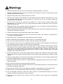
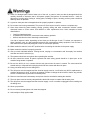
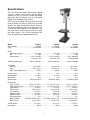
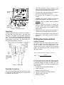
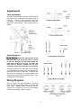
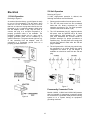
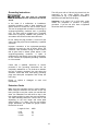
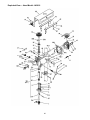
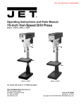
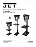
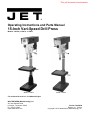
This .pdf document is bookmarked Operating Instructions and Parts Manual 15-Inch Vari-Speed Drill Press Models: J-A3816, J-A5816, J- A5818 Model J-A3816 Model J-A5816 For models with serial no. 11110696 and higher WALTER MEIER (Manufacturing), Inc. 427 New Sanford Road LaVergne, Tennessee 37086 Ph.: 800-274-6848 www.waltermeier.com Part No. M-354500 Revision C1 10/2012 Copyright © 2012 Walter Meier (Manufacturing), Inc. Warranty and Service Lathe Accessories Machine Accessories Mobile Bases Safety Equipment Specialty Items Vise Accessories Air ToolsContractor Air Tools-Industrial Air Tools-Light Industrial Lubrication Palet Trucks Rigging Equip. Service Jacks Stackers Surface Grinders Tapping Trolleys-Air Trolleys-Electric Web Slings Winches-Electric WW Benchtop Tools 5 YEAR WW Drill Presses WW Dust Collectors WW Dust Filters WW Dust Fittings WW Jointers WW Lathes WW Planers WW Shapers WW Sanders WW Tablesaws LIFE LIFETIME WARRANTY 3 YEAR Beam Clamps Chain HoistManual Lever Hoists Pullers-JCH Models Scissor Lift Tables Screw Jacks Trolleys-Geared Trolleys-Plain Winches-Manual WW Air Filtration WW Bandsaws WW Buffers WARRANTY 2 YEAR WARRANTY 1 YEAR Body Repair Kits Bottle Jacks Cable Pullers Cold Saws Hoists-Air Hoists-Electric Metal forming Mill/Drills Milling Machines MW Bandsaws MW Drill Presses MW Finishing Equipment MW Lathes MW Precision Vises WARRANTY DAY WARRANTY 90 WARRANTY Walter Meier (Manufacturing), Inc., warrants every product it sells. If one of our tools needs service or repair, one of our Authorized Service Centers located throughout the United States can give you quick service. In most cases, any of these Walter Meier Authorized Service Centers can authorize warranty repair, assist you in obtaining parts, or perform routine maintenance and major repair on your JET® tools. For the name of an Authorized Service Center in your area call 1-800-2746848. MORE INFORMATION Walter Meier is consistently adding new products to the line. For complete, up-to-date product information, check with your local Walter Meier distributor, or visit waltermeier.com. WARRANTY JET products carry a limited warranty which varies in duration based upon the product. (MW = Metalworking, WW = Woodworking) Fastening Tools Mechanics Hand Tools Striking Tools Vises (no -precision) Clamps Warranty reverts to 1 Year Warranty if woodworking (WW) products listed above are used for industrial or educational purposes. WHAT IS COVERED? This warranty covers any defects in workmanship or materials subject to the exceptions stated below. Cutting tools, abrasives and other consumables are excluded from warranty coverage. WHO IS COVERED? This warranty covers only the initial purchaser of the product. WHAT IS THE PERIOD OF COVERAGE? The general JET warranty lasts for the time period specified in the product literature of each product. WHAT IS NOT COVERED? Five Year Warranties do not cover woodworking (WW) products used for commercial, industrial or educational purposes. Woodworking products with Five Year Warranties that are used for commercial, industrial or education purposes revert to a One Year Warranty. This warranty does not cover defects due directly or indirectly to misuse, abuse, negligence or accidents, normal wear-and-tear, improper repair or alterations, or lack of maintenance. HOW TO GET SERVICE The product or part must be returned for examination, postage prepaid, to a location designated by us. For the name of the location nearest you, please call 1-800-274-6848. You must provide proof of initial purchase date and an explanation of the complaint must accompany the merchandise. If our inspection discloses a defect, we will repair or replace the product, or refund the purchase price, at our option. We will return the repaired product or replacement at our expense unless it is determined by us that there is no defect, or that the defect resulted from causes not within the scope of our warranty in which case we will, at your direction, dispose of or return the product. In the event you choose to have the product returned, you will be responsible for the shipping and handling costs of the return. HOW STATE LAW APPLIES This warranty gives you specific legal rights; you may also have other rights which vary from state to state. LIMITATIONS ON THIS WARRANTY WALTER MEIER (MANUFACTURING), INC., LIMITS ALL IMPLIED WARRANTIES TO THE PERIOD OF THE LIMITED WARRANTY FOR EACH PRODUCT. EXCEPT AS STATED HEREIN, ANY IMPLIED WARRANTIES OR MERCHANTABILITY AND FITNESS ARE EXCLUDED. SOME STATES DO NOT ALLOW LIMITATIONS ON HOW LONG THE IMPLIED WARRANTY LASTS, SO THE ABOVE LIMITATION MAY NOT APPLY TO YOU. WMH TOOL GROUP SHALL IN NO EVENT BE LIABLE FOR DEATH, INJURIES TO PERSONS OR PROPERTY, OR FOR INCIDENTAL, CONTINGENT, SPECIAL, OR CONSEQUENTIAL DAMAGES ARISING FROM THE USE OF OUR PRODUCTS. SOME STATES DO NOT ALLOW THE EXCLUSION OR LIMITATION OF INCIDENTAL OR CONSEQUENTIAL DAMAGES, SO THE ABOVE LIMITATION OR EXCLUSION MAY NOT APPLY TO YOU. Walter Meier sells through distributors only. The specifications in Walter Meier catalogs are given as general information and are not binding. Members of Walter Meier reserve the right to effect at any time, without prior notice, those alterations to parts, fittings, and accessory equipment which they may deem necessary for any reason whatsoever. JET® branded products are not sold in Canada by Walter Meier. 2 Table of Contents Warranty and Service......................................................................................................................................2 Table of Contents ...........................................................................................................................................3 Warnings........................................................................................................................................................4 Safety Instructions for Drill Presses ..............................................................................................................6 ON/OFF Switch Padlock ..............................................................................................................................6 Specifications .................................................................................................................................................7 Introduction ....................................................................................................................................................8 Set-up ............................................................................................................................................................8 Securing the Base .......................................................................................................................................8 Cleaning .....................................................................................................................................................8 Electrical Connection ......................................................................................................................................8 Operating Controls..........................................................................................................................................8 ON/OFF Switch ...........................................................................................................................................8 Speed Control Handwheel ...........................................................................................................................8 Depth Stop..................................................................................................................................................9 Operating Precautions .................................................................................................................................9 Drilling Recommendations ...............................................................................................................................9 Maintenance ................................................................................................................................................ 10 Replacement of Drive Belt.......................................................................................................................... 10 Replacement of Motor ............................................................................................................................... 10 Lubrication ................................................................................................................................................... 10 Adjustments ................................................................................................................................................. 11 Table Adjustment ...................................................................................................................................... 11 Wiring Diagrams ........................................................................................................................................... 11 Electrical ...................................................................................................................................................... 12 115 Volt Operation .................................................................................................................................... 12 230 Volt Operation .................................................................................................................................... 12 Permanently Connected Tools ................................................................................................................... 12 Grounding Instructions ............................................................................................................................... 13 Extension Cords ........................................................................................................................................ 13 Troubleshooting ............................................................................................................................................ 14 Parts ............................................................................................................................................................ 14 Parts List - Head Models J-A5816 and J-A5818........................................................................................... 15 Exploded View — Head Models J-A5816 and J-A5818 ................................................................................ 17 Parts List - Head Model J-A3816 ................................................................................................................ 18 Exploded View — Head Model J-A3816 ...................................................................................................... 20 Parts List – Base Floor Models J-A3816, J-A5816 and J-A5818 ................................................................... 21 Exploded View – Base Floor Models J-A3816, J-A5816 and J-A5818 ........................................................... 22 The specifications in this manual are given as general information and are not binding. Walter Meier (Manufacturing), Inc., reserves the right to effect, at any time and without prior notice, changes or alterations to parts, fittings, and accessory equipment deemed necessary for any reason whatsoever. 3 Warnings 1. Read and understand the entire owner's manual before attempting assembly or operation. 2. Read and understand warnings posted on the machine and in this manual. Failure to comply with all of these warnings may cause serious injury. 3. Replace warning labels if they become obscured or removed. 4. This drill press is designed and intended for use by properly trained and experienced personnel only. If you are not familiar with the proper and safe operation of a drill press, do not use until proper training and knowledge have been obtained. 5. Do not use this drill press for other than its intended use. If used for other purposes, Walter Meier (Manufacturing), Inc., disclaims any real or implied warranty and holds itself harmless from any injury that may result from that use. 6. Keep guards in place and in working order when the machine is in use. If removed for maintenance purposes, use extreme caution and replace the guards immediately. 7. Remove adjusting keys and wrenches. Form habit of checking to see that keys and adjusting wrenches are removed from tool before turning it on. 8. Keep work area clean. Cluttered areas and benches invite accidents. 9. Do not use in dangerous environment. Don't use power tools in damp or wet locations, or expose them to rain. Keep work area well lighted. 10. Keep children away. All visitors should be kept safe distance from work area. 11. Make workshop kid proof with padlocks, master switches, or by removing starter keys. 12. Don't force tool. It will do the job better and safer at the rate for which it was designed. 13. Use the right tool. Don’t force a tool or attachment to do a job for which it was not designed. The right tool will do the job better and more safely at the rate for which it was designed. 14. Use proper extension cord. Make sure your extension cord is in good condition. When using an extension cord, be sure to use one heavy enough to carry the current your product will draw. An undersized cord will cause a drop in line voltage resulting in loss of power and overheating. Table 1 shows the correct size to use depending on cord length and nameplate ampere rating. If in doubt, use the next heavier gage. The smaller the gage number, the heavier the cord. 15. Wear proper apparel. Do not wear loose clothing, gloves, neckties, rings, bracelets, or other jewelry which may get caught in moving parts. Nonslip footwear is recommended. Wear protective hair covering to contain long hair. 16. Always use safety glasses. Also use face or dust mask if cutting operation is dusty. Everyday eyeglasses only have impact resistant lenses, they are NOT safety glasses. 17. Secure work. Make sure the work piece is securely attached or clamped to the table. Never use your hand to hold the work piece. 18. Don't overreach. Keep proper footing and balance at all times. 19. Maintain tools with care. Keep tools sharp and clean for best and safest performance. Follow instructions for lubricating and changing accessories. 20. Disconnect tools before servicing; when changing accessories, such as blades, bits, cutters, and the like. 21. Reduce the risk of unintentional starting. Make sure switch is in off position before plugging in. 22. Use recommended accessories. Consult the owner's manual for recommended accessories. The use of improper accessories may cause risk of injury to persons. 23. Never stand on tool. Serious injury could occur if the tool is tipped or if the cutting tool is unintentionally contacted. 4 24. Check for damaged parts. Before further use of the tool, a guard or other part that is damaged should be carefully checked to determine that it will operate properly and perform its intended function - check for alignment of moving parts, binding of moving parts, breakage of parts, mounting, and any other conditions that may affect its operation. 25. A guard or other part that is damaged should be properly repaired or replaced. 26. Do not leave tool running unattended. Turn power off. Don't leave tool until it comes to a complete stop. 27. Some dust created by power sanding, sawing, grinding, drilling and other construction activities contain chemicals known to cause cancer, birth defects or other reproductive harm. Some examples of these chemicals are: • • • Lead from lead based paint. Crystalline silica from bricks, cement and other masonry products. Arsenic and chromium from chemically treated lumber. Your risk of exposure varies, depending on how often you do this type of work. To reduce your exposure to these chemicals: work in a well-ventilated area and work with approved safety equipment, such as face or dust masks that are specifically designed to filter out microscopic particles. 28. Make certain the switch is in the OFF position before connecting the machine to the power supply. 29. Make certain the machine is properly grounded. 30. Give your work undivided attention. Looking around, carrying on a conversation and “horse-play” are careless acts that can result in serious injury. 31. The operator should not wear gloves when operating the machine. 32. All doors should be closed, all panels replaced and other safety guards should be in place prior to the machine being started or operated. 33. Be sure the drill bit is not in contact with the work piece when the motor is started. The motor should be started and up to full speed before bringing the drill bit into contact with the work piece. 34. Keep your hands away from the drilling area. 35. The drill press must be stopped and the electrical supply must be cut off before any drill bit replacement or machine adjustment is done, or before any attempt is made to change the drive belts or before any periodic service or maintenance is performed on the drill press. 36. Remove loose items and unnecessary work pieces from the area before starting the machine. 37. The work piece must be securely clamped before the drill bit comes in contact with the work piece. 38. The drill press must be stopped and the electrical supply cut off or machine unplugged before reaching into the drilling area. 39. Wear eye protection. 40. Do not remove jammed pieces until motor has stopped. 41. Hold workpiece firmly against table. 5 Safety Instructions for Drill Presses 6. Always wear protective eye wear when operating, servicing or adjusting machinery. Eyewear shall be impact resistant, protective safety glasses with side shields complying with ANSI Z87.1 specifications. Use of the eye wear which does not comply with ANSI Z87.1 specifications could result in severe injury from breakage of eye protection. See Figure B. 1. All work shall be secured using either clamps or a vise to the drill press table. It is unsafe to use your hands to hold any workpiece being drilled. 2. Drill press head and table shall be securely locked to the column before operating the drill press. This must always be checked prior to starting the machine. 3. Always use the correct tooling. Tooling shall always be maintained and properly sharpened. All tooling must be run at the proper speeds and feeds as they apply to the job. Use only recommended accessories and follow those manufacturer’s instructions pertaining to them. Tooling shall be not be forced in to any workpiece but fed according to the proper specifications. Failure to follow these instructions will not only ruin the tooling as well as the machine, but can cause serious injury. 7. When drilling in material which causes dust, a dust mask shall be worn. 8. Avoid contact with coolant, especially guarding the eyes. 9. Non-slip footwear and safety recommended. See Figure C. shoes are 10. Wear ear protectors (plugs or muffs) during extended periods of operation. See Figure D. 4. Never brush away any chips while the machine is in operation. All clean up should be done when the machine is stopped. 5. Keep hands in sight. Do not put hands or fingers around, on, or below any rotating cutting tools. Leather safety gloves should be used when handling any sharp objects or cutting tools. See Figure A. A B C D ON/OFF Switch Padlock For Model Numbers A5816 and A5818 To avoid accidental starting by young children or others not qualified to use the tool, the use of a padlock is required. 1. Open the padlock (Fig E). 2. Insert the through hole in the switch cover. Figure E 3. Close the padlock (Fig F). 4. Place the key in a safe place. 6 Figure F Specifications The JET 15-Inch Vari-Speed Drill Presses, Models J-A3816, J-A5816, and J-A5818 provide drilling speeds from 400 to 5,000 rpm. Simple handwheel adjustment sets the speeds with an LED speed display on the faceplate of the machine. JET's 15-inch vari-speed drill press provides a solid base for drilling and offers a wide range of spindle speeds. The large quill provides greater accuracy. The large worktable provides the operator with room to work and ample support for the workpiece. The drill press has a 3-inch diameter column for head and table support. The 15-Inch Vari-Speed Drill Press is equipped with a standard table raiser. Model J-A3816 J-A5816 J-A5818 Stock Number ......................................... 354500.............................. 354550.............................. 354551 Type ................................................. Floor Model........................ Floor Model........................ Floor Model Motor: Motor Speed (rpm) ...........................1,725 rpm...........................1,725 rpm...........................1,725 rpm HP ......................................................... 1 HP.................................. 1 HP.................................. 1 HP Power Rating .......................... 1 PH, 115/220V.................. 1 PH, 115/220V.................. 3 PH, 220/440V Prewired 115V Prewired 115V Prewired 220V Spindle speeds (rpm) .................. 400 to 5,000rpm ............... 400 to 5,000 rpm................ 400 to 5,000 rpm Capacities: Cast iron....................................... up to 5/8-in. ....................... up to 5/8-in.......................... up to 5/8-in Steel ............................................ up to 1/2-in......................... up to 1/2-in......................... up to 1/2-in. Work Table Weight Cpcty. ..................... 90 lbs................................. 90 lbs................................. 90 lbs. Drills to center ............................................ 15 in.................................. 15 in.................................. 15 in. Quill diameter ..........................................2-1/4 in...............................2-1/4 in............................... 2-1/4 in Quill travel .................................................... 6 in.................................... 6 in.................................... 6 in. Spindle taper ............................... #2 Morse Taper.................. #2 Morse Taper.................. #2 Morse Taper Dimensions: Table (overall) ..................... 15-1/4 x 17-3/4 in................ 15-1/4 x 17-3/4 in................ 15-1/4 x 17-3/4 in. Table (working area) ............ 11-1/4 x 14-1/2 in................ 12-1/2 x 14-1/2 in................ 12-1/2 x 14-1/2 in. Table travel....................................... 16-3/4 in............................. 16-3/4 in............................. 16-3/4 in. Table T-slots................................ two at 1/2 in........................ two at 1/2 in........................ two at 1/2 in. T-slot centers .................................... 5-5/16 in............................. 5-5/16 in............................. 5-5/16 in. Spindle to table ................................. 25-3/4 in............................ 25-3/4 in............................ 25-3/4 in. Spindle to base ................................. 44-1/2 in............................. 44-1/2 in............................. 44-1/2 in. Column diameter...................................... 3 in.................................... 3 in.................................... 3 in. Base (LxWxH) ........... 20-7/8x14-3/16x3-1/8 in...... 20-7/8x14-3/16x3-1/8 in...... 20-7/8x14-3/16x3-1/8 in. Base T-slots ................................ two at 1/2 in........................ two at 1/2 in........................ two at 1/2 in. Overall height ........................................ 67-1/2 in. ........................... 67-1/2 in............................. 67-1/2 in. Net weight ..................................................394 lb.................................426 lb.................................426 lb 7 Introduction Set-up This manual includes operating and maintenance instructions for the JET 15-Inch Vari-Speed Drill Presses, Models J-A3816, J-A5816, and J-A5818. This manual also includes parts listings and illustrations of replaceable parts. Securing the Base The base of the drill press has four mounting holes. The drill press should be level and rest solidly on the floor. Place shims under the four mounting holes in the base as required to level the drill press. Refer to Figure 1 for key features of the drill press. Cleaning LED Speed Display Motor Clean off any protective grease with solvent. After cleaning, lubricate the base, table, and column with a light coating of medium weight machine oil. Repeat at six months intervals. Internal parts of the drill press are lubricated at the factory. No further lubrication is required at the time of installation. Speed setting Handwheel Electrical Connection Refer to the Wiring Diagram section for wiring information. Connection to electrical power should be made by a qualified electrician. Observe local electrical codes when connecting the machine. On/Off Switch Depth Stop Feed Handle Head locking Handle Spindle The motor should be protected with a time delay fuse or circuit breaker with a amperage rating slightly higher than the full load current of the motor. Column Operating Controls (Refer to Figure 2) Work Table Table height adjustment ON/OFF Switch The ON/OFF switch is located at the front of the drill head. Rack Speed Control Handwheel To avoid damage to the speed adjustment mechanism, the motor must be operating before attempting to adjust the speed rate. Base The speed control handwheel is located on the left side of the drill head. An LED speed indicator is provided on the face plate on the drill head. Figure 1 – Drill Press Features 8 1. The head assembly must be locked to the column so the thrust produced by drilling will not force the head assembly up the column. LED Speed Display 2. The work table must be locked to the column so it will not be forced down the column. 3. Be sure the belt is tightened to the proper tension. 4. DO NOT start to drill the workpiece until making certain the workpiece is held down securely. 5. BEFORE turning the speed control handwheel in either direction. Depth Stop Speed control Handwheel 6. Point of operation protection is required for maximum safety. This remains the responsibility of the user/purchaser since conditions differ between jobs. On/Off Switch Figure 2 – Operating Controls 7. Make sure the drill is secured in the spindle or check before attempting to use the drill press. Depth Stop A drilling depth stop (refer to Figure 3) is provided on the right side of the drill head. The depth stop consists of a threaded rod with depth setting jam nuts. The front side of the threaded rod has a depth scale. The jam nuts are loosened and moved to the desired depth on the scale. The upper jam nut is then tightened against the lower nut. 8. Make sure the spindle taper is clean and free of burrs, scoring, and galling to assure maximum gripping. Drilling Recommendations Speeds for Drilling The speed of a drill is usually measured in terms of the rate at which the outer periphery of the tool moves in relation to the work being drilled. The common term for this is Surface Feet per Minute (SFM). The relationship of SFM is expressed in the following formulas: SFM = 0.26 × RPM × Drill Diameter (in Inches ) RPM = 3.8 × SFM Drill Diameter (in Inches ) In general, the higher the speed the shorter the drill life. Operating at the low end of the speed range for a particular material will result in longer life. The most efficient speed for operating a drill depends on many variables: Figure 3 – Depth Stop 1. 2. 3. 4. 5. 6. Operating Precautions The following operating and safety precautions must be observed in order to avoid harm to the operator or damage to the drill press. 9 Composition and hardness of material. Depth of the hole. Efficiency of the cutting fluid. Type and condition of the drilling machine. Desired quality of the hole. Difficulty of set-up. Indication of Extreme Speeds and Feeds 3. Remove head cover. A drill that splits up the web is evidence of too much feed or insufficient tip clearance at the center as a result of improper grinding. The rapid wearing away of the extreme outer corners of the cutting edges indicates that the speed is too high. A drill chipping or breaking out at the cutting edges indicates that either the feed is too heavy or the drill has been ground with too much tip clearance. 4. Remove belt. (With speed control setting at the highest speed, the belt should be loose enough to remove.) 5. Install the replacement belt. Install the head cover. 6. Connect electrical power to the drill press. 7. Operate the operation. Speeds for High Speed Steel Drills Material Speed In SFM Alloy Steel — 300 to 400 Brinell .................... 20 - 30 Stainless Steel............................................. 30 - 40 Automotive Steel Forgings ........................... 40 - 50 Tool Steel, 1.2C........................................... 50 - 60 Steel, .4C to .5C .......................................... 70 - 80 Mild Machinery Steel, .2C to .3C................. 80 - 110 Hard Chilled Cast Iron .................................. 30 - 40 Medium Hard Cast Iron .............................. 70 - 100 Soft Cast Iron .......................................... 100 – 150 Malleable Iron............................................. 80 – 90 High Nickel Steel or Monel .......................... 40 – 50 High Tensile Bronze.................................... 70 -150 Ordinary Brass and Bronze ...................... 200 - 300 Aluminum and its Alloys ........................... 200 - 300 Magnesium and its Alloys ......................... 250 - 400 Slate, Marble, and Stone ............................... 15 -25 Plastics and similar material (Bakelite) ...... 100 - 150 Wood ....................................................... 300 -400 Titanium Alloys ............................................ 10 - 25 Titanium Alloy Sheet .................................... 50 - 60 drill press to verify correct Replacement of Motor Make sure to disconnect electrical power to the drill press to avoid the possibility of inadvertent operation and exposure to potentially lethal voltage levels. 1. Disconnect electrical power to drill press. 2. Remove drive belt (see Replacement of Drive Belt). 3. Disconnect electrical wiring from motor junction box. 4. Remove nuts and washers from bolts securing motor to drill head. Remove motor. 5. Remove pulleys and related components from motor shaft. 6. Install pulleys and related components on replacement motor shaft. 7. Install motor on mounting bolts and secure with nuts and washers. General Applications 8. Connect electrical wiring (refer Diagram section for wiring details). 5mm hole ................................................ 550 - 600 10mm hole .............................................. 250 - 300 15mm hole .............................................. 100 - 110 to Wiring 9. Install drive belt (see Replacement of Drive Belt). 10. Operate drill press to verify proper operation. In cases where carbon steel drills are applicable, the drill should be run at speeds of from 40 to 50 percent of those given above. Lubrication Following are lubrication recommendations for drill press components. Maintenance Spindle pulley drive: Lubricate spindle splines occasionally with light grease. Quill, Table, and Column: Lubricate with light film of oil. Table lift rack: Lubricate regularly with SAE20 oil (clean rack with solvent before applying oil.) Variable speed drive fork: Lubricate contact points occasionally with grease. Replacement of Drive Belt Make sure to disconnect electrical power to the drill press to avoid the possibility of inadvertent operation and exposure to potentially lethal voltage levels. 1. Start drill press. Set speed control to highest speed. Stop drill press. 2. Disconnect electrical power to drill press. 10 Adjustments Table Adjustment The table can be raised or lowered to accommodate the height of the component being drilled (refer to Figure 4). To raise or lower the table, loosen the lock handle. Then use the hand crank to move the table to the desired height. Then retighten the lock handle. Figure 4 – Table Adjustment Head Adjustment Change the radial position of the drill head only if the drill press base is secured to the floor. Swinging the drill head without the base being secured to the floor will cause the drill press to become unstable and tip over resulting in injury and/or damage to the machine. The radial position of the drill head can be changed to accommodate the drilling of a hole that may be offset from the center of the table. Reposition the drill head by loosening the locking handles and swinging the drill head to the desired position. Then retighten the locking handles. Wiring Diagrams Refer to Figure 5 for wiring information. The drive motor is115/230 volt single phase or 220/440 volt three phase. Notice: When converting machine voltage, it is necessary to re-wire the LED display connection accordingly. Refer to figure 5. Figure 5 11 230 Volt Operation Electrical Referring to Figure 7: 115 Volt Operation If 230V, single-phase operation is desired, the following instructions must be followed: Referring to Figure 6: 1. Disconnect the machine from the power source. As received from the factory, your drill press is ready to run at 115-volt operation. This drill press, when wired for 115 volt, is intended for use on a circuit that has an outlet and a plug that looks like the one illustrated in (A). A temporary adapter, which looks like the adapter shown in (B), may be used to connect this plug to a two-pole receptacle if a properly grounded outlet is not available. The temporary adapter should only be used until a properly grounded outlet can be installed by a qualified electrician. The green colored rigid ear, lug, or tab, extending from the adapter, must be connected to a permanent ground such as a properly grounded outlet box. 2. The JET drill press motor has four numbered leads that are factory connected for 115V operation, as shown in (A). For 230V operation reconnect the leads as shown in (B). 3. The 115V attachment plug (C), supplied with the drill press, must be replaced with a UL listed plug suitable for 230V operation (D). Contact your local Authorized JET Service Center or qualified electrician for proper procedures to install the plug. The drill press must comply with all local and national codes after the 230-volt plug is installed. 4. The drill press with a 230-volt plug should only be connected to an outlet having the same configuration as shown in (D). No adapter is available nor should be used with the 230-volt plug. A B Figure 7 Permanently Connected Tools Models J-A3816, J-A5816 and J-A5818 drill presses that are intended for permanent connection should be connected to a grounded metal permanent wiring system or to a system having an equipmentgrounding conductor. Figure 6 12 Grounding Instructions The drill press with a 230-volt plug should only be connected to an outlet having the same configuration (D, Fig. 7). No adapter is available or should be used with the 230-volt plug. This tool must be grounded while in use to protect the operator from electric shock. Important: In all cases (115 or 230 volts), make certain the receptacle in question is properly grounded. If you are not sure, have a registered electrician check the receptacle. In the event of a malfunction or breakdown, grounding provides a path of least resistance for electric current to reduce the risk of electric shock. This tool is equipped with an electric cord having an equipment-grounding conductor and a grounding plug. The plug must be plugged into a matching outlet that is properly installed and grounded in accordance with all local codes and ordinances. Do not modify the plug provided. If it will not fit the outlet, have the proper outlet installed by a qualified electrician. Improper connection of the equipment-grounding conductor can result in a risk of electric shock. The conductor, with insulation having an outer surface that is green with or without yellow stripes, is the equipment-grounding conductor. If repair or replacement of the electric cord or plug is necessary, do not connect the equipment-grounding conductor to a live terminal. Check with a qualified electrician or service personnel if the grounding instructions are not completely understood, or if in doubt as to whether the tool is properly grounded. Use only three wire extension cords that have three-prong grounding plugs and three-pole receptacles that accept the tool’s plug. Repair or replace a damaged or worn cord immediately. Extension Cords Make sure your extension cord is in good condition. When using an extension cord, be sure to use one heavy enough to carry the current your machine will draw. An undersized cord will cause a drop in the line voltage resulting in power loss and overheating. The table following shows the correct size to use depending on the cord length and name plate ampere rating. If in doubt, use the next heavier gauge. Remember, the smaller the gauge number, the heavier the cord. Length of Cord AWG 0–25 25-50 51-100 16 14 12 13 Troubleshooting Problem Spindle does not turn. Spindle noisy. Drill stalls. Probable Cause Suggested Remedy Circuit breaker tripped. Reset circuit breaker. Branch circuit breaker tripped or fuse blown. Reset Open wire in switch circuit. Repair open circuit. Defective switch. Repair switch. Broken drive belt. Replace drive belt. Damaged spindle bearings. Replace bearings. Worn spline. Replace spline. Worn drive belt. Check condition of belt. Replace if glazed or branch circuit breaker/replace fuse. slipping on pulleys Excessive feed rate for size of drill and material being drilled. Reduce feed pressure or use cutting fluid No cutting fluid or improper cutting fluid. Use correct cutting fluid. Drill dull Sharpen drill. Lack of rigidity in hold-down method. Check that all T-slot hold-downs are tight and that table-lock and drill head bolts are tight. Speed too fast for material and drill size. Check spindle speed recommendations. Reduce speed if necessary. Feed too fast for material and drill size. Reduce feed rate. No or improper cutting fluid or coolant being used. Use cutting fluid, or change to proper fluid or coolant for material being drilled. Improperly ground drill bit. Check for proper angles and reliefs. Regrind to proper geometry. Electrical circuit fault. Check current draw in circuit. Make sure current draw is the same as rating on motor plate. Oversize drill. Reduce drill size. Excessive feed. Reduce feed rate. No cutting fluid, or wrong fluid Use correct cutting fluid for the material and drill. Table cannot be raised. Lack of lubrication Lubricate. No speed readout. Speed pickup out of adjustment or failed. Adjust gap between speed pickup and post spindle pulley. If there is no readout on the speed indicator, replace the speed pickup. Poorly drilled holes. Motor overheating Parts Ordering Replacement Parts To order parts or reach our service department, call 1-800-274-6848 Monday through Friday (see our website for business hours, www.waltermeier.com). Having the Model Number and Serial Number of your machine available when you call will allow us to serve you quickly and accurately. 14 Parts List - Head Models J-A5816 and J-A5818 Item Part No. Description Size Qty. 1 .............. 5507580 ..................Chuck (with Key) ................................................................................ 1 2A............ 5507495 ..................Arbor ...............................................................#2 MT x JT3 ............... 1 3A............ 5507496A................Spindle .............................................................................................. 1 4 .............. J-5053070 ...............Quill Band .......................................................................................... 1 5 .............. 9010541 ..................O-Ring ............................................................................................... 1 6 .............. 9054511 ..................Set Screw ........................................................5/16-18 x 3/8 .............. 2 6-1 ........... 9054511A................Flat Head Screw ..............................................M6x16........................ 1 7 .............. 5032611 ..................Bearing Retainer ................................................................................ 1 8 .............. 9100331 ..................Bearing ............................................................6203ZZ ...................... 1 8-1 ........... 9100331A................Bearing ............................................................6204ZZ ...................... 1 9 .............. 5041010 ..................Quill .................................................................................................. 1 10 ............ 9058561 ..................Wavy Spring Washer .......................................................................... 1 11 ............ 9074081 ..................Truarc Retainer .................................................................................. 1 13 ............ 9056981 ..................Hex Jam Nut ....................................................1/4-20 ........................ 3 16 ............ 5518170 ..................Sloted self taping Screw ....................................3/16-24 x 3/8 .............. 4 17 ............ 5518157 ..................Power Cord (1-Phase) ........................................................................ 1 17A.......... 5517463 ..................Power Cord (3-Phase) ........................................................................ 1 18A.......... 5507500 ..................Switch (Single Phase) ......................................................................... 1 ................ 5507497 ..................Switch (3-Phase) ................................................................................ 1 19A.......... 5507501 ..................Slotted Machine Screw .....................................1/4-20 x 1 ................... 4 21 ............ 5518158 ..................Wiring Harness (1-Phase) ................................................................... 1 ................ 5517457 ..................Wiring Harness (3-Phase) ................................................................... 1 24A.......... 5507502 ..................Socket Head Cap Screw ..................................................................... 3 25A.......... 5507503 ..................Return Spring Assemlby...................................................................... 1 26A.......... 5507504 ..................Nylon Nut ........................................................................................... 1 27 ............ 9135311 ..................Lock Screw ......................................................1/4-20 x 1 ................... 2 28 ............ J-5041050 ...............Speed Change Housing ...................................................................... 1 29 ............ 9127731 ..................Socket Set Screw .............................................5/16-18 x 5/16 ............ 1 30 ............ 5024541 ..................Head Lock (Plain Side) ....................................................................... 1 31 ............ 1000772 ..................Lock Nut Assembly ............................................................................. 1 32 ............ 5041071 ..................Speed Change Shaft........................................................................... 1 33 ............ 9053661 ..................Retainer ............................................................................................. 1 34 ............ 5041201 ..................Bearing Spacer................................................................................... 1 35 ............ 9100321 ..................Bearing .............................................................................................. 2 36 ............ 9070291 ..................Knob .................................................................................................. 3 37 ............ 5053000 ..................Spoke ................................................................................................ 3 38 ............ J-5507827 ...............Feed Shaft Assembly .......................................................................... 1 39 ............ 5513378 ..................Hi/Lo Speed Direction Plate................................................................. 1 40 ............ 5053100A................Rod, Graduated .................................................................................. 1 41 ............ 9056381 ..................Jam Nut ...........................................................5/8-11 ........................ 3 41-1 ......... 9056381A................Nut M10xP1.5/Spring Washer M10 ...................................................... 1 42 ............ 9128611 ..................Hex Head Cap Screw........................................1/2-12 x 4 ................... 1 44 ............ TS-0270031 ............Set Screw ........................................................5/16-18 x 3/8 .............. 4 45-1 ......... 5032781-1 ...............Motor Plate Bar (serial no: 11110696 and higher) ...................................... 4 46 ............ 9057111 ..................Whiz Flange Locknut .......................................................................... 4 47 ............ TS-0152051 ............Carriage Bolt ...................................................5/16-18 x 2 ................. 2 48 ............ 9056171 ..................Carriage Bolt ....................................................5/16-18 x 1-1/2 ........... 4 49-1 ......... 9058051-1 ...............Set Screw (serial no: 11110696 and higher) ............5 /16” ......................... 4 51A.......... A5816-51A ..............Lower Pulley ...................................................................................... 1 51B.......... A5816-51B ..............Upper Pulley ...................................................................................... 1 51C ......... A5816-51C ..............Spring ................................................................................................ 1 51D ......... A5816-51D ..............Spring Support Cover.......................................................................... 1 52 ............ 9054621 ..................Socket Set Screw ............................................1/4-20 x 1/2 ................ 2 53 ............ 5042011 ..................Key (Motor) ........................................................................................ 1 54 ............ 9077101 ..................Variable Speed Belt ............................................................................ 1 15 Parts List - Head Models J-A5816 and J-A5818 Item Part No. Description Size Qty. 55 ............ 5041140 ..................Vaiable Speed Pulley (Spindle)............................................................ 1 55A.......... 5513510 ..................Hex Nut ............................................................................................. 1 55B.......... 5513511 ..................SHCS ............................................................................................... 1 56 ............ 9100421 ..................Bearing .............................................................................................. 1 57 ............ 9058571 ..................Spring Washer ................................................................................... 1 58 ............ 5041761 ..................Speed Change Nut ............................................................................. 1 59 ............ 5041040 ..................Speed Change Lever .......................................................................... 1 60 ............ 9127951 ..................Socket Set Screw ............................................. 1/4-20 x 1/2 ............... 1 61 ............ 9057461 ..................Washer ............................................................ 1/4 ............................ 3 62 ............ 9052101 ..................Hex Head Cap Screw .......................................1/4-20 x 1 ................... 4 63 ............ J-5041271 ...............Right Mounting Plate........................................................................... 1 64 ............ 5518170 ..................Self Tapping Screw ..........................................3/16-24 x 3/8 .............. 7 68A.......... TS-0208041 ...........SHCS .............................................................5/16-18x3/4 ................ 2 68B.......... 5513513 ..................Spacer, Threaded ............................................................................... 1 68C ......... 5513514 ..................Plate, Bracket ..................................................................................... 1 68D ......... 5513515 ..................Pickup, Magnetic ................................................................................ 1 68E.......... 5513516 ..................Screw ................................................................................................ 2 68F .......... 5513521 ..................Plate .................................................................................................. 1 69 ............ J-5041320 ...............Cover, Pulley ...................................................................................... 1 69A.......... J-5513517 ...............Bracket, Face Plate ............................................................................ 1 70 ............ J-5513518 ...............Plate, Face ......................................................................................... 1 70A.......... 5513519 ..................LED Display 1Ph ................................................................................ 1 ................ 5513736 ..................LED Display 3 Ph ................................................................................. 70B.......... 5513520 ..................Screw, Locking ................................................................................... 2 72 ............ 9056771 ..................Hex Jam Nut ....................................................3/8-16 ........................ 1 75 ............ J-5041000 ...............Head Casting ..................................................................................... 1 76 ............ J-5518172 ...............Left Mounting Plate ............................................................................. 1 77 ............ 9052831 ..................Socket Set Screw .............................................3/8-16 x 1 ................... 1 78 ............ TS-0267101 ............Socket Set Screw .............................................1/4-20 x 1-1/4 ............. 2 80 ............ 9052971 ..................Socket Set Screw ............................................5/16-18 x 5/16 ............ 1 81 ............ 5034111 ..................Hand Wheel ....................................................................................... 1 82 ............ 5513737 ..................Shaft speed change lever .................................................................... 1 86 ............ 9129051 ..................Hex Nut............................................................7/16-14 ...................... 1 87 ............ 5041470 ..................Collar ................................................................................................. 1 88 ............ 9128071 ..................Hex Head Cap Screw .......................................7/16-14 x 3-1/2 ........... 1 89-1 ......... J-5032560-1 ............Motor Mounting Bracket (Serial no: 11110696 and higher) ......................... 1 94 ............ TS-0680032 ............Washer ............................................................5/16 ........................... 8 96 ............ 5507505 ..................Return Spring Bracket ......................................................................... 1 97 ............ 5507507 ..................Drift Pin .............................................................................................. 1 98 ............ 5507506 ..................Switch Mounting Plate......................................................................... 1 99 ............ 5507527A................Quill Assembly (see Note) ................................................................... 1 100 .......... J-A5816-100-1-1 ......Motor, 1 PH 115/220 .........................................1725 RPM 60 Hz ........ 1 ................ A5816-100-2 ...........Motor, 1PH 115/220 ..........................................1725 RPM 50 Hz ....... 1 ................ J-A5818-100-1 .........Motor, 3 PH 220/440 .........................................1725 RPM 50/60 Hz ... 1 101 .......... A5816-01 ................Motor Plate......................................................................................... 1 110 .......... A5816-02 ................Connect Box ...................................................................................... 1 111 .......... A5816-03 ................Strain Relief ....................................................................................... 1 Note: ...... Quill assembly includes items 3A, 5, 8, 8-1, 9, and 11. 16 Exploded View — Head Models J-A5816 and J-A5818 17 Parts List - Head Model J-A3816 Item Part No. Description Size Qty. 1 .............. 5507580 ..................Chuck (with Key) ................................................................................ 1 2A............ 5507495 ..................Arbor ...............................................................#2 MT x JT3 .............. 1 3A............ 5507496A................Spindle Assembly .............................................................................. 1 4 .............. J-5053070 ...............Quill Band .......................................................................................... 1 5 .............. 9010541 ..................O-Ring ............................................................................................... 1 6 .............. 9054511 ..................Set Screw ........................................................5/16-18 x 3/8 .............. 2 6-1 ........... 9054511A................Flat Head Screw ...............................................M6 x 16 ...................... 1 7 .............. 5032611 ..................Bearing Retainer ................................................................................ 1 8 .............. 9100331 ..................Bearing ............................................................6203ZZ ...................... 1 8-1 ........... 9100331A................Bearing ............................................................6204ZZ ...................... 1 9 .............. 5041010 ..................Quill .................................................................................................. 1 10 ............ 9058561 ..................Wavy Spring Washer .......................................................................... 1 11 ............ 9074081 ..................Truarc Retainer .................................................................................. 1 13 ............ 9056981 ..................Hex Jam Nut ....................................................1/4-20 ........................ 3 16 ............ 9052711 ..................Self Tapping Screw ...........................................8-32 x 3/8 ................... 4 17 ............ 5518157 ..................Power Cord (Single Phase) ................................................................. 1 17A.......... 5517463 ..................Power Cord (3-Phase) ........................................................................ 1 18A.......... 5507500 ..................Switch (Single Phase) ......................................................................... 1 ................ 5507497 ..................Switch (3-Phase) ................................................................................ 1 19A.......... 5507501 ..................Slotted Machine Screw ....................................................................... 4 21 ............ 5518158 ..................Wiring Harness (1-Phase) ................................................................... 1 ................ 5517457 ..................Wiring Harness (3-Phase) ................................................................... 1 24A.......... 5507502 ..................Socket Head Cap Screw ..................................................................... 3 25A.......... 5507503 ..................Return Spring Assemlby...................................................................... 1 26A.......... 5507504 ..................Nylon Nut ........................................................................................... 1 27 ............ 5518159 ..................Phillips Screw ...................................................1/4-20 x 5/16 .............. 2 28 ............ 5518160 ..................Cover Plate ........................................................................................ 1 29 ............ 9127731 ..................Socket Set Screw .............................................5/16-18 x 5/16 ............ 1 30 ............ 5024541 ..................Head Lock (Plain Side) ....................................................................... 1 31 ............ 1000772 ..................Lock Nut Assembly ............................................................................. 1 33 ............ 9053661 ..................Retainer ............................................................................................. 1 34 ............ 5041201 ..................Bearing Spacer................................................................................... 1 35 ............ 9100321 ..................Bearing .............................................................................................. 2 36 ............ 9070291 ..................Knob .................................................................................................. 3 37 ............ J-5053000 ...............Spoke ................................................................................................ 3 38 ............ J-5507827 ...............Feed Shaft Assembly .......................................................................... 1 40 ............ 5053100A................Rod, Graduated .................................................................................. 1 41 ............ 9056381 ..................Jam Nut ...........................................................5/8-11 ........................ 3 41-1 ......... 9056381A................Nut ….M10xP1.5/Spring Washer .......................M10 ........................... 1 42 ............ 9128611 ..................Hex Head Cap Screw........................................1/2-13 x 4 ................... 1 44 ............ 9052191 ..................Socket Set Screw .............................................5/16-18 x 1/2 .............. 4 45-1 ......... 5032781-1 ...............Motor Plate Bar (Serial no: 11110696 and higher)...................................... 4 46 ............ 9057111 ..................Whiz Flange Locknut .......................................................................... 4 48 ............ 9056171 ..................Carriage Bolt ....................................................5/16-18 x 1-1/2 ........... 4 49-1 ......... 9058051-1 ...............Set Screw (Serial no: 11110696 and higher)............5/16” .......................... 4 51 ............ 5518161 ..................Step Pulley (Motor) ............................................................................. 1 52 ............ 5518162 ..................Socket Set Screw .............................................1/4-20 x 5/16 .............. 2 53 ............ 5042011 ..................Key (Motor) ........................................................................................ 1 54 ............ 5518163 ..................Drive Belt..............OPTI VARIO 22x8x1140 or PYRA MID 1422V 470 .... 1 55 ............ 5518164 ..................Step Pulley (Spindle) .......................................................................... 1 55A.......... 5518165 ..................Spindle Pulley Shaft ............................................................................ 1 55B.......... 5518166 ..................Key ..................................................................5 x 45......................... 1 57 ............ 9058571 ..................Spring Washer ................................................................................... 2 61 ............ 9057461 ..................Washer ............................................................1/4 ............................. 3 62 ............ 9052101 ..................Hex Head Cap Screw........................................1/4-20 x 1 ................... 4 63 ............ J-5518167 ...............Mounting Plate ................................................................................... 1 18 Parts List - Head Model J-A3816 Item Part No. Description Size Qty. 64 ............ 9138011 ..................Self Tapping Screw ...........................................#10 x 3/4 Type A ........ 4 69 ............ J-5518168 ...............Pulley Cover (w/door & latch) .............................................................. 1 70 ............ J-5518169 ...............Face Plate.......................................................................................... 1 75 ............ J-5041000 ...............Head Casting ..................................................................................... 1 76 ............ J-5518167L .............Left Mounting Plate ............................................................................. 1 86 ............ 9129051 ..................Hex Nut............................................................7/16-14 ...................... 1 87 ............ J-5041470 ...............Collar ................................................................................................. 1 88 ............ 9128071 ..................Hex Head Cap Screw .......................................7/16-14 x 3-1/2 ........... 1 89-1 ......... J-5032560-1 ............Motor Mounting Bracket (Serial no: 11110696 and higher) ......................... 1 94 ............ 9055281 ..................Rubber Washer .................................................................................. 4 96 ............ 5507505 ..................Return Spring Bracket ......................................................................... 1 97 ............ 5507507 ..................Drift Pin .............................................................................................. 1 98 ............ 5507506 ..................Switch Mounting Plate......................................................................... 1 99 ............ 5507527A................Quill Assembly (see Note) ................................................................... 1 100 .......... J-5507812 ...............Motor, 1 PH 115/220 .........................................1725 RPM 60 Hz ........ 1 ................ J-5514604 ...............Motor, 1PH 115/220 ..........................................1725 RPM 50 Hz ....... 1 ................ J-5507813 ...............Motor, 3 PH 220/440 .........................................1725 RPM 50/60 Hz ... 1 Note: Quill assembly includes items 5, 7, 8, 8-1, 9, 10 and 11. 19 Exploded View — Head Model J-A3816 20 Parts List – Base Floor Models J-A3816, J-A5816 and J-A5818 Item Part No. Description Size Qty. 1 .............. 1000772 ..................Locknut .............................................................................................. 1 2 .............. 5003751 ..................Table Lock (Plain Side) ....................................................................... 1 3 .............. J-5507508 ...............Table ................................................................................................. 1 4 .............. 5507509 ..................Hex Head Cap Screw.......................................................................... 1 5 .............. TS-0061091 ............Cap Screw .......................................................7/16-14 x 3-1/2 ........... 1 6 .............. J-5041470 ...............Collar ................................................................................................. 1 7 .............. 9129051 ..................Hex Nut............................................................7/16-14 ...................... 1 8 .............. J-5507528 ...............Base .................................................................................................. 1 9 .............. 5507510 ..................Standard Column................................................................................ 1 ................ 5511850 ..................Short Column ..................................................................................... 1 10 ............ J-5507511 ...............Flange (Base/Column) ........................................................................ 1 11 ............ 5630771 ..................HHCS ..............................................................1/2-12 x 1-1/2 ............. 4 12 ............ J-5507571 ...............Cover Plate ........................................................................................ 1 13 ............ 5507570 ..................Bushing.............................................................................................. 1 14 ............ 5507513 ..................Worm, Table Raiser ............................................................................ 1 15 ............ 5507514 ..................Gear, Table Raiser ............................................................................. 1 16 ............ 5507515 ..................Shaft, Table Raiser ............................................................................. 1 17 ............ 5507516 ..................C-Ring, Table Raiser .......................................................................... 2 18 ............ TS-0050051 ...........SHCS ..............................................................1/4 x 1........................ 4 19 ............ 5507518 ..................Socket Head Set Screw ....................................5/16-18 x 3/8 .............. 1 20 ............ J-5507519 ...............Crank, Table Raiser ............................................................................ 1 21 ............ 5507520 ..................Handle, Table Raiser .......................................................................... 1 22 ............ 5507521 ..................Rack .................................................................................................. 1 23 ............ J-5507522 ...............Rack Ring .......................................................................................... 1 25 ............ 5507816 ..................Table Raiser Assembly (includes index# 12 thru 17) ............................. 1 21 Exploded View – Base Floor Models J-A3816, J-A5816 and J-A5818 22 Notes 23 Walter Meier (Manufacturing), Inc. 427 New Sanford Road LaVergne, Tennessee 37086 Phone: 800-274-6848 www.waltermeier.com 24