1
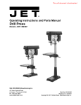
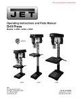
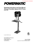
This .pdf document is bookmarked Operating Instructions and Parts Manual 17" Floor Drill Press Model: JDP-17DX WALTER MEIER (Manufacturing) Inc. 427 New Sanford Road LaVergne, Tennessee 37086 Ph.: 800-274-6848 www.jettools.com Part No. M-354173 Revision C1 11/2013 Copyright © 2013 Walter Meier (Manufacturing) Inc. Warranty and Service JET, Wilton and Powermatic warrants every product they sell against manufacturers’ defects. If one of our tools needs service or repair, please contact Technical Service by calling 1-800-274-6846, 8AM to 5PM CST, Monday through Friday Warranty Period The general warranty lasts for the time period specified in the literature included with your product or on the official JET, Wilton or Powermatic branded websites. • JET, Wilton and Powermatic products carry a limited warranty which varies in duration based upon the product. (See chart below) • Accessories carry a limited warranty of one year from the date of receipt. • Consumable items are defined as expendable parts or accessories expected to become inoperable within a reasonable amount of use and are covered by a 90 day limited warranty against manufacturer’s defects. Who is Covered This warranty covers only the initial purchaser of the product from the date of delivery. What is Covered This warranty covers any defects in workmanship or materials subject to the limitations stated below. This warranty does not cover failures due directly or indirectly to misuse, abuse, negligence or accidents, normal wear-and-tear, improper repair, alterations or lack of maintenance. Warranty Limitations Woodworking products with a Five Year Warranty that are used for commercial or industrial or education purposes revert to a One Year Warranty. Please contact Technical Service at 1-800-274-6846 for further clarification. How to Get Technical Support Please contact Technical Service by calling 1-800-274-6846. Please note that you will be asked to provide proof of initial purchase when calling. If a product requires further inspection, the Technical Service representative will explain and assist with any additional action needed. JET, Wilton and Powermatic have Authorized Service Centers located throughout the United States. For the name of an Authorized Service Center in your area call 1-800-274-6846 or use the Service Center Locator on the JET, Wilton or Powermatic website. More Information JET, Wilton and Powermatic are consistently adding new products. For complete, up-to-date product information, check with your local Walter Meier distributor or visit the JET, Wilton or Powermatic website. How State Law Applies This warranty gives you specific legal rights, subject to applicable state law. Limitations on This Warranty JET, WILTON AND POWERMATIC LIMIT ALL IMPLIED WARRANTIES TO THE PERIOD OF THE LIMITED WARRANTY FOR EACH PRODUCT. EXCEPT AS STATED HEREIN, ANY IMPLIED WARRANTIES OF MERCHANTABILITY AND FITNESS FOR A PARTICULAR PURPOSE ARE EXCLUDED. SOME STATES DO NOT ALLOW LIMITATIONS ON HOW LONG AN IMPLIED WARRANTY LASTS, SO THE ABOVE LIMITATION MAY NOT APPLY TO YOU. JET, WILTON AND POWERMATIC SHALL IN NO EVENT BE LIABLE FOR DEATH, INJURIES TO PERSONS OR PROPERTY, OR FOR INCIDENTAL, CONTINGENT, SPECIAL, OR CONSEQUENTIAL DAMAGES ARISING FROM THE USE OF OUR PRODUCTS. SOME STATES DO NOT ALLOW THE EXCLUSION OR LIMITATION OF INCIDENTAL OR CONSEQUENTIAL DAMAGES, SO THE ABOVE LIMITATION OR EXCLUSION MAY NOT APPLY TO YOU. JET, Wilton and Powermatic sell through distributors only. The specifications listed in JET, Wilton and Powermatic printed materials and on official JET, Wilton and Powermatic-branded websites are given as general information and are not binding. JET, Wilton and Powermatic reserve the right to effect at any time, without prior notice, those alterations to parts, fittings, and accessory equipment which they may deem necessary for any reason whatsoever. ® JET branded products are not sold in Canada by Walter Meier Manufacturing Americas. Product Listing with Warranty Period 90 Days – Parts; Consumable items; Light-Duty Air Tools 1 Year – Motors; Machine Accessories; Heavy-Duty Air Tools; Pro-Duty Air Tools 2 Year – Metalworking Machinery; Electric Hoists, Electric Hoist Accessories 5 Year – Woodworking Machinery Limited Lifetime – Wilton branded products; JET Parallel clamps; Manual Hoists; Manual Hoist Accessories; Shop Tools; Warehouse & Dock products; Hand Tools NOTE: JET, Wilton and Powermatic are divisions of Walter Meier Manufacturing Americas. References in this document to JET, Wilton and/or Powermatic also apply to Walter Meier Manufacturing Americas or any of its successors in interest to the JET, Wilton and/or Powermatic brands. 2 Table of Contents Warranty and Service .............................................................................................................................. 2 Table of Contents .................................................................................................................................... 3 Warnings ................................................................................................................................................. 4 Switch Padlock..................................................................................................................................... 5 Introduction ............................................................................................................................................. 6 Unpacking ............................................................................................................................................... 7 Contents of the Shipping Container ...................................................................................................... 7 Assembly ................................................................................................................................................ 8 Base and Column Assembly ................................................................................................................ 8 Table and Rack.................................................................................................................................... 8 Table Crank and Column Lock Handles ............................................................................................... 8 Mounting the Head ............................................................................................................................... 9 Downfeed Handles............................................................................................................................... 9 Installing the Chuck and Arbor.............................................................................................................. 9 Electrical ............................................................................................................................................... 10 Grounding Instructions ....................................................................................................................... 10 115 Volt Operation Only ..................................................................................................................... 10 Extension Cords................................................................................................................................. 10 Adjustments .......................................................................................................................................... 11 Removing the Chuck and Arbor.......................................................................................................... 11 Adjusting the Depth Stop.................................................................................................................... 11 Changing Spindle Speeds .................................................................................................................. 11 Return Spring Adjustment .................................................................................................................. 12 Table Tilt Adjustment ......................................................................................................................... 12 Laser Adjustment ............................................................................................................................... 13 Laser Assembly Removal/Installation ................................................................................................. 14 Lamp ................................................................................................................................................. 14 Operating Controls ................................................................................................................................ 15 Basic Operation ..................................................................................................................................... 15 Lubrication............................................................................................................................................. 15 Troubleshooting..................................................................................................................................... 16 Parts ..................................................................................................................................................... 17 Ordering Replacement Parts .............................................................................................................. 17 Parts List............................................................................................................................................ 17 Assembly Drawing ............................................................................................................................. 21 Wiring Diagram...................................................................................................................................... 22 The specifications in this manual are given as general information and are not binding. Walter Meier (Manufacturing) Inc., reserves the right to effect, at any time and without prior notice, changes or alterations to parts, fittings, and accessory equipment deemed necessary for any reason whatsoever. 3 Warnings 1. 2. • Read and understand the entire owners' manual before attempting assembly or operation. Read and understand the warnings posted on the machine and in this manual. Failure to comply with all of these warnings may cause serious injury. Replace the warning labels if they become obscured or removed. This drill press is designed and intended for use by properly trained and experienced personnel only. If you are not familiar with the proper and safe operation of a drill press, do not use until proper training and knowledge have been obtained. Do not use this drill press for other than its intended use. If used for other purposes, Walter Meier (Manufacturing) Inc., disclaims any real or implied warranty and holds itself harmless from any injury that may result from that use. Always wear approved safety glasses/face shields while using this drill press. Everyday eyeglasses only have impact resistant lenses; they are not safety glasses. Before operating this drill press, remove tie, rings, watches and other jewelry, and roll sleeves up past the elbows. Remove all loose clothing and confine long hair. Non-slip footwear or anti-skid floor strips are recommended. Do not wear gloves. Wear ear protectors (plugs or muffs) during extended periods of operation. Some dust created by power sanding, sawing, grinding, drilling and other construction activities contain chemicals known to cause cancer, birth defects or other reproductive harm. Some examples of these chemicals are: Lead from lead based paint. • Crystalline silica from bricks, cement and other masonry products. • Arsenic and chromium from chemically treated lumber. 3. 4. 5. 6. 7. 8. 9. Your risk of exposure varies, depending on how often you do this type of work. To reduce your exposure to these chemicals, work in a well-ventilated area and work with approved safety equipment, such as face or dust masks that are specifically designed to filter out microscopic particles. 10. 11. 12. 13. 14. 15. 16. 17. 18. 19. 20. 21. 22. Do not operate this machine while tired or under the influence of drugs, alcohol or any medication. Make certain the switch is in the OFF position before connecting the machine to the power supply. Make certain the machine is properly grounded. Make all machine adjustments or maintenance with the machine unplugged from the power source. Remove adjusting keys and wrenches. Form a habit of checking to see that keys and adjusting wrenches are removed from the machine before turning it on. Keep safety guards in place at all times when the machine is in use. If removed for maintenance purposes, use extreme caution and replace the guards immediately. Make sure the drill press is firmly secured to the floor or bench before use. Check damaged parts. Before further use of the machine, a guard or other part that is damaged should be carefully checked to determine that it will operate properly and perform its intended function. Check for alignment of moving parts, binding of moving parts, breakage of parts, mounting and any other conditions that may affect its operation. A guard or other part that is damaged should be properly repaired or replaced. Provide for adequate space surrounding work area and non-glare, overhead lighting. Keep the floor around the machine clean and free of scrap material, oil and grease. Don't use in dangerous environment. Don't use power tools in damp or wet locations, or expose them to rain. Keep work area well lighted. Keep visitors a safe distance from the work area. Keep children away. Make your workshop child proof with padlocks, master switches or by removing starter keys. 4 23. Give your work undivided attention. Looking around, carrying on a conversation and “horse-play” are careless acts that can result in serious injury. 24. Maintain a balanced stance at all times so that you do not fall or lean against the spindle or other moving parts. Do not overreach or use excessive force to perform any machine operation. 25. Use the right tool at the correct speed and feed rate. Do not force a tool or attachment to do a job for which it was not designed. The right tool will do the job better and safer. 26. Use recommended accessories; improper accessories may be hazardous. 27. Maintain tools with care. Keep drill bits sharp and clean for the best and safest performance. Follow instructions for lubricating and changing accessories. 28. Disconnect tools before servicing; when changing accessories, such as blades, bits, cutters and the like. 29. Make sure the work piece is securely attached or clamped to the table. Never use your hand to hold the work piece. 30. Turn off the machine before cleaning. Use a brush or compressed air to remove chips or debris — do not use your hands. 31. Do not stand on the machine. Serious injury could occur if the machine tips over. 32. Never leave the machine running unattended. Turn the power off and do not leave the machine until it comes to a complete stop. 33. Remove loose items and unnecessary work pieces from the area before starting the machine. Familiarize yourself with the following safety notices used in this manual: This means that if precautions are not heeded, it may result in minor injury and/or possible machine damage. This means that if precautions are not heeded, it may result in serious injury or possibly even death. Switch Padlock To safeguard your machine from unauthorized operation and to avoid accidental starting by young children, the use of a padlock (not supplied) is highly recommended. To lock out an on-off switch: 1. Open the padlock (Fig. A). 2. Insert through holes in the start button (Fig. B). 3. Close the padlock. 4. Place the key in a safe place. Figure A 5 Figure B Introduction This manual is provided by Walter Meier (Manufacturing) Inc., covering the safe operation and maintenance procedures for the JET JDP-17DX Drill Press. This manual contains instructions on installation, safety precautions, general operating procedures, maintenance instructions and parts breakdown. This machine has been designed and constructed to provide years of trouble free operation if used in accordance with instructions set forth in this manual. If there are any questions or comments, please contact either your local supplier or Walter Meier. Walter Meier can also be reached at our web site: www.waltermeier.com. Specifications Model Number ...........................................................................................................................JDP-17DX Stock Number................................................................................................................................ 354173 Swing (in.) ....................................................................................................................................... 16-1/2 Type .................................................................................................................................................. Floor Drilling Capacity (in.)............................................................................................................................. 5/8 Chuck Size (in.) .................................................................................................................................... 5/8 Spindle Travel (in.) ............................................................................................................................ 4-3/8 Maximum Spindle Distance to Base (in.) ................................................................................................ 49 Maximum Spindle Distance to Table (in.) ......................................................................................... 29-1/8 Table Size (in./WxD)........................................................................................................... 18-1/2 x 14-1/2 Table Insert (in.) ............................................................................................................. 2-11/16 x 2-11/16 Table Tilt (deg.) ........................................................................................................................... + or – 45 Table slots width (in.)........................................................................................................................... 1/2 Table T-slots (in./WxD) ............................................................................................................. 11/16 x 3/8 Spindle Taper .................................................................................................................................... MT-2 Column Diameter (in.)........................................................................................................................ 3-1/8 Number of Spindle Speeds .................................................................................................................... 16 Range of Spindle Speeds (RPM) ............................................................................................... 230-3,630 Light Bulb (not included) ............................................................................................................ 60W max. Overall Height (in.)................................................................................................................................. 65 Base Size (in.) .................................................................................................................... 12-1/2 x 19-5/8 Motor............................................................................................... TEFC, 3/4 HP, 1 Ph, 115V only, 60Hz Cord Length (ft.) ...................................................................................................................................... 6 Net Weight – approx. (lbs.) .................................................................................................................. 200 Shipping Weight – approx. (lbs.) .......................................................................................................... 215 The above specifications were current at the time this manual was published, but because of our policy of continuous improvement, Walter Meier reserves the right to change specifications at any time and without prior notice, without incurring obligations. Read and understand the entire contents of this manual before attempting assembly or operation! Failure to comply may cause serious injury! 6 Unpacking Separate all parts from the packing material. Check each part against the Contents of the Shipping Container and make certain that all items are accounted for before discarding any packing material. Contents of the Shipping Container A B C D E F G H J K N O P --- Head Assembly (1) Table and Bracket Assembly (1) Table Insert (1) Base (1) Column and Rack Assembly (1) Downfeed Handle (3) Arbor (1) Drift Key (1) Column Lock Handle (1) Chuck Key (1) Chuck (1) M10 x 40 Hex Cap Screws (4) Table Bracket Position Handle (1) Owner’s Manual (1) Warranty Registration Card Tools Supplied for Assembly L 3mm Hex Wrench M 5mm Hex Wrench Tools Required for Assembly -- 17mm Box Wrench or a 6”-8” Adjustable Wrench Read and understand all assembly instructions before attempting assembly! Failure to comply may cause serious injury! Contents of Shipping Container Before Assembly 1. Remove the contents from the shipping container. 2. Compare the contents of the shipping container with the list found above. Report any shortages or damage to your JET distributor. 3. Clean all rust protected surfaces with kerosene or a light solvent. Do not use lacquer thinner, paint thinner, or gasoline. These will damage plastic components and painted surfaces. Hardware Package (p/n JDP17DX-HP) 7 Assembly Base and Column Assembly Referring to Figure 1: 1. Place the base (A) on a level floor. 2. Place the column assembly (B) on the base (A) and align the holes in the column support with the holes in the base. 3. Using a 17mm wrench, secure the column (B) with four M10 x 40 hex cap screws (C) to the base. Figure 1 Table and Rack Referring to Figure 2: When shipped, the rack ring (E) and rack (F) are bundled together with the column (D) in plastic wrap. 1. Remove the wrap and take the rack ring (E) and rack (F) off the column (D). Note which end of the rack is up. It must be reinstalled later with the same side up. 2. Place the rack (F) inside the table bracket (G) such that the teeth of the rack (F) mesh with the pinion gear on the end of the table crank handle shaft (H). 3. Slide the table and bracket assembly (B, G) together with the rack (F) onto the column (D) as shown. 4. Slide the rack ring (E) onto the column (D), placing it so it rests against the rack (F) as shown and tighten the setscrew (C) with a 3mm hex wrench. Table Crank and Column Lock Handles Referring to Figure 2: Figure 2 1. Loosen the setscrew (J) on the table crank handle (K). 2. Slide the handle (K) onto the table bracket shaft (H). 3. Turn the handle (K) until the setscrew (J) is on the flat section of the shaft (H) and tighten the setscrew (J) with a 3mm hex wrench to secure the handle. 4. Thread the column lock handle (A) into the back side of the table bracket (G) opposite the crank handle (G). 8 Mounting the Head 1. With the aid of a second person, carefully lift the head onto the column top (Figure 3). The head assembly is heavy! To avoid injury and/or damage to equipment, lift the head onto the column only with additional assistance! 2. Rotate head assembly until sides of the belt cover (E) are parallel with the sides of the base (A, Fig. 1). 3. Tighten two set screws (A, Fig. 3) with a 5mm wrench until they are snug. Figure 3 Downfeed Handles Referring to Figure 3: For right-handed operation, install three downfeed handles (B) into the downfeed hub (C) as shown. For left-handed operation, install the downfeed handles into the hub on the left side of the head. Installing the Chuck and Arbor 1. Lower the table out of the way of the spindle assembly (D, Fig. 3). Referring to Figure 4: 2. Thoroughly clean spindle (A), arbor (C), and chuck (D). Important: These three pieces must be free of any rust protection, or lubricant. If they are not clean, the arbor and chuck will fail to seat in the spindle. 3. Place arbor (C) into the chuck (D). 4. Twist the chuck to completely retract the chuck jaws if they are exposed. 5. Place arbor and chuck assembly into the spindle (A). 6. Turn the arbor and chuck assembly until the tang (B) on the arbor (C) engages the slot at the end of the spindle. 7. Use a rubber mallet, or a steel hammer against a block of wood, to sharply tap the bottom of the chuck two or three times to seat the chuck/arbor assembly. (Note: Do not use a steel hammer directly against the chuck.) Figure 4 9 adapter, which looks like the adapter shown in (B), may be used to connect this plug to a twopole receptacle if a properly grounded outlet is not available. The temporary adapter should only be used until a properly grounded outlet can be installed by a qualified electrician. This adapter is not applicable in Canada. The green colored rigid ear, lug, or tab, extending from the adapter, must be connected to a permanent ground such as a properly grounded outlet box. Electrical Grounding Instructions In the event of a malfunction or breakdown, grounding provides a path of least resistance for electric current to reduce the risk of electric shock. This tool is equipped with an electric cord having an equipment-grounding conductor and a grounding plug. The plug must be plugged into a matching outlet that is properly installed and grounded in accordance with all local codes and ordinances. Do not modify the plug provided – if it will not fit the outlet, have the proper outlet installed by a qualified electrician. Improper connection of the equipmentgrounding conductor can result in a risk of electric shock. The conductor with insulation having an outer surface that is green with or without yellow stripes is the equipmentgrounding conductor. If repair or replacement of the electric cord or plug is necessary, do not connect the equipment-grounding conductor to a live terminal. Figure 5 Extension Cords Make sure your extension cord is in good condition. When using an extension cord, be sure to use one heavy enough to carry the current your machine will draw. An undersized cord will cause a drop in the line voltage resulting in power loss and overheating. The table below shows the correct size to use depending on the cord length and nameplate ampere rating. If in doubt, use the next heavier gauge. Remember, the smaller the gauge number, the heavier the cord. Check with a qualified electrician or service personnel if the grounding instructions are not completely understood, or if in doubt as to whether the tool is properly grounded. Use only 3-wire extension cords that have 3prong grounding plugs and 3-pole receptacles that accept the tool’s plug. Repair or replace damaged or worn cord immediately. Cord Length 00 – 25ft 25 – 50ft 115 Volt Operation Only AWG 016 014 Important: Make certain the receptacle in question is properly grounded. If you are not sure, have a registered electrician check the receptacle. Referring to Figure 5: As received from the factory, your drill press is ready to run at 115-volt operation. This drill press, when wired for 115 volt, is intended for use on a circuit that has an outlet and a plug that looks like the one illustrated in (A). A temporary 230 330 380 470 540 600 700 770 830 900 1550 1650 1800 2380 2540 3630 Figure 6 –Drill Speed Chart: Spindle Speeds in RPM 10 Adjustments Removing the Chuck and Arbor Referring to Figure 7: 1. Unplug machine from the power source. 2. Raise the table until it is about seven inches below the chuck. 3. Place a piece of scrap wood on the table, and lower quill (E) using the downfeed handle (A, C). 4. Still maintaining the lowered quill position, rotate spindle to align the key hole in the spindle with the key hole in the quill (E). Figure 7 5. Insert the drift key (D) into the aligned slots and tap lightly. The chuck and arbor assembly should fall from the spindle. Prepare to catch the chuck and arbor as it drops. Striking the floor could damage tool. Adjusting the Depth Stop Referring to Figure 8: To drill multiple holes at the same preset depth, use the depth stop as follows: 1. Use a pencil to mark the depth the bit will drill into the workpiece (A). 2. With the drill bit in the chuck, lower down feed handle to advance bit to your mark. 3. With your other hand, advance the lock nut (C1) on the depth stop rod until they are snug to the seat (B). Tighten C2 against C1. 4. The drill bit will now advance to this point. 5. To release, advance the nuts counterclockwise to the top of the depth stop. Changing Spindle Speeds A spindle speed and belt arrangement chart (Figure 6) is found on the inside of the belt cover. Refer to this chart whenever changing speeds. To change spindle speeds (refer to Figure 7): Figure 8 4. Change the belts location according the speed chart and the speed you desire. 5. Rotate the tension adjuster (F) to tension the belts. 1. Unplug the machine from the power source. 2. Loosen two bar knobs (G), one found on each side of the head assembly. 3. Rotate the tension adjuster (F) to bring the motor base as close to the head as possible. 6. Tighten two bar knobs (G). Belts are properly tensioned when moderate pressure with finger and thumb midway between the two pulleys causes approximately ½” deflection. Tighten two bar knobs (G). 11 Return Spring Adjustment Figure 9 The return spring is located behind the left downfeed handle hub. It is adjusted at the factory and should not need further adjustment. 5. Rotate the coil spring cover (M) until the notch on the cover engages with the tab (L) on the head casting. Turn the cover clockwise to decrease tension and counterclockwise to increase tension. If adjustment is deemed necessary: 1. Unplug the machine from the power source. 6. Replace flat washer (G) and key (F). Referring to Figure 9: 2. Remove Items A–G in that order. A 19mm wrench is required to loosen the hex nut (B). 7. Tighten hex nut (J) firmly by hand against the cover (M), then secure by tightening the jam nut (H) against the hex nut (J). 3. Loosen the two jam nuts (H, J). Do not remove. 8. Reinstall the hub (E), flat washer (D) and spring washer (C). 4. Pull out slightly the coil spring cover (M) while firmly holding it. DO NOT allow the coil spring cover to turn freely in your hand, or the spring will unwind. 9. Reinstall and tighten jam nut (B). 10. Reinstall the hub cover (A). Table Tilt Adjustment Remove the alignment pin first and then loosen the hex cap bolt. Failure to comply may cause the table assembly to separate from the column and fall. To tilt the table (referring to Figure 10): 1. Turn nut (C) clockwise to pull out the alignment pin (B). 2. Loosen hex cap screw (A), and tilt the table to the desired angle. 3. Tighten the hex cap screw (A). Figure 10 4. Reinsert the alignment pin (B). The alignment pin only works at 90° and must be reinserted when the table is returned to 90°. 12 Laser Adjustment The Laser Assembly has been installed and preset at the factory. It should, however, be checked and adjustments made, if necessary, before operating the drill press. It should also be rechecked periodically, as constant machine use may cause it to become misaligned. Make verifications and align as follows: Referring to Figure 11: 1. Take a length of board (F) and draw a perpendicular line (E) on one side using a square. 2. Place a small drill bit (C) in the chuck (B), then place the board (F) on the table on edge against the drill bit (C) with the marked line side facing toward the laser to be aligned (A1 in this case). Figure 11 Important: The table should be in horizontal position and locked. 3. Connect power to the drill press and turn on the laser using the button at the front of the drill press head. Two parallel laser markings will appear that should look like G and H in Figure 11 – the distance between the lines will vary with board thickness; however, the lines must be parallel to each other and the marked line (vertical alignment). Figure 12 If alignment is necessary: Vertical Alignment (refer to Figure 11) 5. Make slight adjustments to four setscrews (K1-4, Fig. 12) and move the board (F) from side to side as required until the laser light (D) lines up with the board marking (E). 6. Tighten all four setscrews so they are snug against the laser housing, but do not over tighten. Verify that the laser light is still lined up with board marking. 7. Adjust the other laser in the same manner. Two resulting parallel laser markings should look like G and H in Figure 11 – the distance between the lines can vary but must be parallel to each other and the marked line. Cross Hair Alignment (refer to Figure 13) 8. Place board (M) flat on the table. Do not allow the board to move from this position; use clamps if needed. Bring the bit down until it leaves a slight perforation in the board (O) then raise it back up. 9. Turn on the laser to check if the cross-hairs intersect at the perforation. If adjustment is required: 10. Choosing first one laser (A1 in this case), loosen two setscrews on the same side (either side) of the laser housing equal amounts about 1/4 turn or less. Figure 13 11. Adjust (L1) so the laser line (N1) crosses the perforation (O); then retighten setscrews. 12. Adjust the other laser assembly in the same manner until both laser lines form crosshairs (N1, N2) exactly over the perforation (O) in the board. 13. Recheck the vertical alignment to insure that the laser lines did not shift during the tightening process. The laser is now calibrated properly and the location of your holes can be centered at the crosshairs for accurate drilling. 13 Laser Assembly Removal/Installation The JDP-17DX drill press can be used as a mortiser when fitted with a mortiser adapter (not included). When used as a mortiser, the laser assembly must be removed as follows: Referring to Figure 14: 1. Unplug machine from the power source. 2. Remove the chuck and arbor assembly (described on page 7). 3. Remove nuts (A, C), and washer (B) from the depth set bolt (H2). 4. With a 5mm hex wrench, loosen the socket head cap screw (J) on the laser housing (H) and lower the assembly. 5. Disconnect wiring connectors E1, E2. This completes the removal of the laser assembly. To re-install the laser assembly: 1. Reconnect the wiring. Note that each E1 connector can be connected to any E2 connector (order is not important). 2. Install the laser by passing the sleeve (H1) and depth seat bolt (H2) through the head casting opening (F) and seat (D) respectively, then seating the laser housing (H) onto the quill (G). 3. Secure assembly by tightening socket head cap screw (J). This completes the laser assembly installation. Figure 14 Important: After installation, lasers must be recalibrated as described in the Laser Adjustment section (page 13). Lamp A light bulb is not included. If desired, insert a standard 60W bulb into the socket accessible from bottom of head. 14 Operating Controls Basic Operation Refer to Figure 15: Start Switch (A) – Press to start machine Always use a back-up piece of scrap wood to cover the table. This protects both the table and the drill bit. Stop Switch (B) – Press to stop machine Place material to be drilled in such a way as to come into contact with the left side of the column. This prevents the material from spinning. Light Switch (C) – Turns lamp on and off Laser Switch (D) – Turns laser on and off Downfeed Handle (E) – Lower and raise drill If the work piece is not large enough to come into contact with the column, use a clamp or drill press vise that is securely fastened to the table! Table Height Adjust Handle (F) – Raises and ––lowers table; table lock handle (A, Fig. 2) ––needs to be unlocked. Failure to comply may cause serious injury! Feed the bit into the material with only enough force to allow the drill bit to work. Feeding too slowly may cause burning of the workpiece. Feeding too quickly may cause the motor to stop and/or the drill bit to break. Generally speaking, the smaller the drill bit, the greater the RPM required. Wood requires higher speeds than metal. Metal is usually drilled at slower speeds. In dusty environments, frequently blow out any dust that accumulates inside the motor. Lubrication Periodically lubricate the gear and the rack, the table elevation mechanism, the splines (grooves) in the spindle, and the teeth of the quill with #2 tube grease. Figure 15 15 Troubleshooting Trouble Probable Cause 1. Remedy 1. Check all plug connections. 2. 3. 4. Drill press unplugged from wall or motor. Fuse blown or circuit breaker tripped. Cord damaged. Starting capacitor bad. 2. Replace fuse or reset circuit breaker. 3. 4. Replace cord. Replace starting capacitor. 1. Extension cord too light or too long. 1. 2. Low current. 2. Replace with adequate size and length cord. Contact a qualified electrician. 1. Stand on uneven surface. 1. 2. Bad belt(s). 2. 1. Incorrect belt tension. 1. 2. Dry spindle. 2. 3. Loose spindle pulley. 3. 4. Loose motor pulley. 4. 1. Incorrect Speed. 1. 2. Chips not clearing from hole or bit. 2. 3. 4. Dull drill bit. Feeding too slowly. 3. 4. Change to appropriate speed – see speed and pulley chart on page 13. Retract drill bit frequently to remove chips. Resharpen, or replace drill bit. Increase feed rate. 1. 2. 3. Bit sharpened incorrectly. Bent drill bit. Bit or chuck not installed properly. 1. 2. 3. Resharpen bit correctly. Replace drill bit. Reinstall the chuck, or bit properly. 1. No backing board used. 1. Place a scrap board underneath the workpiece to prevent splintering. Drill bit binds in workpiece. 1. 2. 3. 4. Workpiece pinching the bit. Excessive feed rate. Chuck jaws not tight. Improper belt tension. 1. 2. 3. 4. Support or clamp workpiece. Decrease feed rate. Tighten chuck jaws. Increase belt tension (page 12). Excessive drill bit run out, or wobble. 1. 2. 3. Bent drill bit. Worn spindle bearings. Bit, or chuck not properly installed. 1. 2. 3. Replace drill bit. Replace spindle bearings. Reinstall the bit, or chuck properly. Quill returns too slow, or too fast. 1. Spring has improper tension. 1. Adjust “Return Spring Tension,” page 14. Chuck, or arbor do not stay in place. 1. Dirt, grease, etc on arbor, chuck, or spindle. 1. Clean all mating surfaces thoroughly with a cleaner degreaser. Drill press will not start. Drill press does not come up to speed. Drill Press vibrates excessively. Noisy Operation. Workpiece Burns. Drill bit wanders. Wood splinters on the underside. 16 Adjust stand so that it rests evenly on the floor. Replace belts. Adjust belt tension. See Chang-ing Spindle Speeds on page 12. Lubricate spindle. See Lubrication on page 15. Check tightness of retaining nut on pulley and tighten if necessary. Tighten set screws in pulleys. Parts Ordering Replacement Parts To order parts or reach our service department, call 1-800-274-6848 Monday through Friday (see our website for business hours, www.waltermeier.com). Having the Model Number and Serial Number of your machine available when you call will allow us to serve you quickly and accurately. Parts List Index No Part No Description Size Qty 1............... JDP17DX-001 ..........Motor Assembly..................................................................................... 1 2............... 8907522151………. .Motor..................................................................3/4HP,1Ph,115V......... 1 ................. 82061041 .................Motor Fan (not shown) ........................................................................... 1 ................. 89075161 .................Motor Fan Cover (not shown) ................................................................ 1 ................. 2992A55A14 ............Capacitor (not shown).........................................200MFD, 125VAC ...... 1 ................. 299155BA04 ............Centrifugal Switch (not shown) .............................................................. 1 3............... JDP17DX-003 ..........Parallel Key ........................................................6x6x30 ....................... 1 4............... TS-1540061 .............Hex Nut ..............................................................M8 .............................. 4 5............... 10703414 .................Motor Base .........................................................75x125 ....................... 1 6............... JDP17DX-006 ..........Hex Washer Head Cap Screw ............................M8x25 ........................ 4 7............... TS-152706 ...............Hex Wrench .......................................................5mm ........................... 1 8............... TS-152704 ...............Hex Wrench .......................................................3mm ........................... 1 ................. JDP17DX-TBA .........Table and Bracket Assembly (includes # 9,12,23,27,31-34) ................... 1 9............... JDP17DX-009 ..........Table (must order JDP17DX-TBA) ......................................................... 1 10 ............. JDP17DX-010 ..........Insert ..................................................................................................... 1 11 ............. 10602205 .................Rack...................................................................................................... 1 12 ............. 2658MZDU36 ..........Drive Screw ........................................................Dia. 2.3-5 ................... 4 13 ............. TS-1525021 .............Set Screw...........................................................M10x12……………….. 1 14 ............. TS-1491061 .............Hex Cap Screw ..................................................M10x40 ...................... 4 15 ............. 10601901 .................Column Lock Handle ............................................................................. 1 16 ............. 10601009A1 ............Crank Handle Assembly ........................................................................ 1 17 ............. 10600902 .................Worm .................................................................................................... 1 18 ............. JDP17DX-018 ..........Rack Ring Assembly.............................................................................. 1 19 ............. 10702307A1 ............Rack Ring.............................................................................................. 1 20 ............. TS-1523021 .............Set Screw...........................................................M6x8 .......................... 1 21 ............. 12909001 .................Column.................................................................................................. 1 ................. 12909001A1 ............Column and Holder Assembly................................................................ 1 22 ............. 10700207 .................Column Holder ...................................................................................... 1 23 ............. JDP17DX-023 ..........Table Bracket Assembly (includes # 24-26) ........................................... 1 24 ............. 10600702 .................Gear ...................................................................................................... 1 25 ............. 10600802 .................Gear Shaft ............................................................................................. 1 26 ............. JDP17DX-026 ..........Table Bracket ........................................................................................ 1 27 ............. JDP17DX-027 ..........Location Pin Assembly (includes # 28,29) .............................................. 1 28 ............. TS-0561011 .............Hex Nut ..............................................................1/4-20 ......................... 1 29 ............. 10901402 .................Location Pin .......................................................................................... 1 30 ............. 10600111 .................Base ...................................................................................................... 1 31 ............. TS-0071011 .............Hex Cap Screw ..................................................5/8-11x1-1/2 ............... 1 32 ............. JDP17DX-032 ..........Nut .....................................................................5/8-11UNC T=15 ....... 1 33 ............. JDP17DX-033 ..........Centering Scale ..................................................................................... 1 34 ............. JDP17DX-034 ..........Tilting Scale........................................................................................... 1 35 ............. 10611201 .................Chuck Key Holder.................................................................................. 1 36 ............. JDP17DX-036 ..........Depth Set Bolt Assembly (includes # 37-39) .......................................... 1 37 ............. 2658MZDU36 ..........Drive Screw ........................................................Dia.2.3-5 .................... 2 38 ............. JDP17DX-038 ..........Depth Set Bolt ....................................................................................... 1 39 ............. 10904616 .................Scale ..................................................................................................... 1 40 ............. 10661801 .................Circular Nut ........................................................................................... 1 17 Parts List Index No Part No Description Size Qty 41 ............. 10661102 .................Seat ...................................................................................................... 1 42 ............. 13005601 .................Washer.................................................................................................. 1 43 ............. 13005701 .................Nut ........................................................................................................ 2 44 ............. TS-1503081 .............Socket Head Cap Screw.....................................M6x35 ........................ 2 45 ............. TS-1540071 .............Hex Nut ..............................................................M10 ............................ 1 46 ............. TS-1540071 .............Hex Nut ..............................................................M10 ............................ 1 47 ............. TS-2361101 .............Lock Washer ......................................................M10 ............................ 1 48 ............. TS-1534042 .............Pan Head Machine Screw ..................................M6x12 ........................ 1 49 ............. 10905116 .................Seat ...................................................................................................... 1 50 ............. JDP17DX-050 ..........Head ..................................................................................................... 1 51 ............. JDP17DX-051 ..........Laser Assembly (includes # 52-60 and 155)........................................... 1 52 ............. JDP17DX-052 ..........Upper Cover Plate ................................................................................. 1 53 ............. JDP17DX-053 ..........Laser Housing ....................................................................................... 1 54 ............. JDP17DX-054 ..........Sleeve ................................................................................................... 1 55 ............. JDP17DX-055 ..........Laser Sleeve Assembly ......................................................................... 2 56 ............. JDP17DX-056 ..........Laser ..................................................................................................... 1 57 ............. JDP17DX-057 ..........Laser Sleeve ......................................................................................... 1 58 ............. TS-1532032 .............Pan Head Machine Screw ..................................M4x8 .......................... 4 59 ............. TS-1504051 .............Socket Head Cap Screw.....................................M8x25 ........................ 1 60 ............. TS-1523011 .............Socket Set Screw ...............................................M6x6 .......................... 8 61 ............. JDP17DX-061 ..........Handle Assembly (Set of 3) (includes # 62,63)....................................... 1 62 ............. JDP17DX-062 ..........Handle Bar ............................................................................................ 3 63 ............. JDP17DX-063 ..........Handle Grip ........................................................................................... 3 64 ............. TS-1540081 .............Hex Nut ..............................................................M12 ............................ 2 65 ............. 10714001 .................Motor Bar .............................................................................................. 1 66 ............. TS-2361121 .............Lock Washer ......................................................M12 ............................ 2 67 ............. 10703211 .................Motor Bar .............................................................................................. 1 68 ............. JDP17DX-068 ..........Motor Bar Shifter Assembly (includes # 69,70) ....................................... 1 69 ............. TS-1490021 .............Hex Cap Screw ..................................................M8x16 ........................ 1 70 ............. JDP17DX-070 ..........Motor Bar Shifter ................................................................................... 1 71 ............. 2658MZDU36 ..........Drive Screw ........................................................Dia.2.3-5 .................... 8 72 ............. 10902901 .................Handle Shifter........................................................................................ 1 73 ............. TS-1525021 .............Socket Set Screw ...............................................M10x12 ...................... 2 74 ............. JDP17DX-074 ..........Hub ....................................................................................................... 1 75 ............. JDP17DX-075 ..........Spring Pin...........................................................5-16............................ 1 76 ............. 10604505 .................Scale Ring ............................................................................................. 1 77 ............. 10605403 .................Quill Set Screw ...................................................M10 ............................ 1 78 ............. JDP17DX-078 ..........Spring Cap Assembly (includes # 79-81) ............................................... 1 79 ............. 10905203 .................Spring Retainer ..................................................................................... 1 80 ............. JDP17DX-080 ..........Spring Cap ............................................................................................ 1 81 ............. JDP17DX-081 ..........Coil Spring............................................................................................. 1 82 ............. JDP17DX-082 ..........Key........................................................................................................ 1 83 ............. TS-0561052 .............Hex Nut ..............................................................1/2-20UNF.................. 1 84 ............. TS-0571052 .............Hex Jam Nut ......................................................1/2-20UNF.................. 2 85 ............. TS-0680061 .............Flat Washer ........................................................1/2 .............................. 1 86 ............. JDP17DX-086 ..........Hub ....................................................................................................... 1 87 ............. TS-0720111 .............Lock Washer ......................................................1/2 .............................. 1 88 ............. JDP17DX-088 ..........Cover .................................................................................................... 1 89 ............. 10903302 .................Bar Bolt ................................................................................................. 2 90 ............. 2536MBE616 ...........Spring Pin.............................................................................................. 2 91 ............. TS-1534052 .............Pan Head Machine Screw ..................................M6x16 ........................ 4 92 ............. TS-0680021 .............Flat Washer ........................................................1/4 .............................. 4 93 ............. TS-0680061 .............Flat Washer ........................................................1/2 .............................. 1 94 ............. JDP17DX-094 ..........Feed Shaft............................................................................................. 1 ................. JDP17DX-FHA .........Feed Hub Assembly (includes # 74,75, and 94) ..................................... 1 18 Parts List Index No Part No Description Size Qty 95 ............. JDP17DX-095 ..........Rubber Seal .......................................................................................... 1 96 ............. JDP17DX-096 ..........Pulley Cover Assembly .......................................................................... 1 97 ............. JDP17DX-097 ..........Chuck & Key ......................................................................................... 1 98 ............. 561708 ....................Drill Chuck ..........................................................5/8”............................. 1 99 ............. 2136ABD109 ...........Drill Chuck Key ...................................................5/8" ............................ 1 100 ........... JDP17DX-100 ..........Driving Sleeve Assembly (includes # 101-104)....................................... 1 101 ........... BB-6205ZZ ..............Ball Bearing ........................................................6205ZZ....................... 2 102 ........... 10706802 .................Retaining Ring ....................................................................................... 2 103 ........... 10706705 .................Collar .................................................................Dia.50......................... 1 104 ........... 10706508A1 ............Driving Sleeve ....................................................................................... 1 105 ........... 10606904 .................Pulley Set Nut........................................................................................ 1 106 ........... JDP17DX-106 ..........Motor Pulley Assembly .......................................................................... 1 107 ........... TS-1524031 .............Socket Set Screw ...............................................M8x12 ........................ 1 108 ........... JDP17DX-108 ..........Motor Pulley .......................................................................................... 1 109 ........... JDP17DX-109 ..........Center Pulley Assembly (includes # 110-113) ........................................ 1 110 ........... BB-6202ZZ ..............Ball Bearing ........................................................6202ZZ....................... 2 111 ........... JDP17DX-111 ..........Center Pulley......................................................................................... 1 112 ........... JDP17DX-112 ..........Extension Spring ................................................................................... 1 113 ........... JDP17DX-113 ..........Center Pulley Shaft................................................................................ 1 114 ........... JDP17DX-114 ..........Spindle Pulley........................................................................................ 1 115 ........... JDP17DX-115 ..........V-Ribbed Belt .....................................................290J4 ......................... 2 116 ........... 10705703 .................Rubber Washer ..................................................................................... 1 117 ........... JDP17DX-117 ..........Spindle Assembly (includes # 118-124) ................................................. 1 118 ........... BB-6205ZZ ..............Ball Bearing ........................................................6205ZZ....................... 1 119 ........... BB-6203ZZ ..............Ball Bearing ........................................................6203ZZ....................... 1 120 ........... 10606401 .................Spindle Nut............................................................................................ 1 121 ........... 10606301 .................Lock Nut ................................................................................................ 1 122 ........... 10606201 .................Washer...............................................................D=17.5 T=2 ................ 1 123 ........... 10905829 .................Spindle .................................................................................................. 1 124 ........... 10905612 .................Quill....................................................................................................... 1 125 ........... 10607303 .................Drift Key ................................................................................................ 1 126 ........... 561766 ....................Drilling Arbor ......................................................MT2XJT3 ................... 1 127 ........... 994542 ....................Push Button Switch ............................................................................... 1 128 ........... JDP17DX-128 ..........Cord Clamp ........................................................................................... 1 129 ........... TS-1533062 .............Pan Head Machine Screw ..................................M5x20 ........................ 2 130 ........... 2801ABRF04 ...........Strain Relief ........................................................................................... 2 131 ........... 2801ABRF01 ...........Strain Relief ........................................................................................... 1 132 ........... 2653MBDE15 ..........Tapping Screw ...................................................M4x20 ........................ 2 133 ........... 10216715 .................Grounding Label .................................................................................... 1 134 ........... TS-1534052 .............Pan Head Machine Screw ..................................M6x16 ........................ 2 135 ........... TS-1533042 .............Pan Head Machine Screw ..................................M5x12 ........................ 1 136 ........... TS-0733031 .............External Tooth Lock Washer ...............................#10 ............................. 2 137 ........... TS-1533032 .............Pan Head Machine Screw ..................................M5x10 ........................ 2 138 ........... TS-1533052 .............Pan Head Machine Screw ..................................M5x16 ........................ 1 139 ........... JDP17DX-139 ..........Switch Box ............................................................................................ 1 140 ........... JDP17DX-140 ..........Lamp Socket Assembly ......................................................................... 1 141 ........... JDP17DX-141 ..........Power Cable .......................................................................................... 1 142 ........... JDP17DX-142 ..........Lead Wire Assembly.............................................................................. 1 143 ........... JDP17DX-143 ..........Cord Clamp ........................................................................................... 4 144 ........... TS-1533032 .............Pan Head Machine Screw ..................................M5x10 ........................ 4 145 ........... JDP17DX-145 ..........Controller Assembly .............................................................................. 1 146 ........... JDP17DX-146 ..........Lamp Rocker Switch.............................................................................. 1 147 ........... JDP17DX-147 ..........Laser Rocker Switch .............................................................................. 1 148 ........... JDP17DX-148 ..........Tapping Screw ...................................................M3x10 ........................ 1 19 Parts List Index No Part No Description Size Qty 149 ........... JDP17DX-149 ..........Locking Cable Tie .................................................................................. 1 150 ........... JDP17DX-150 ..........Cable Clamp ......................................................................................... 1 151 ........... JDP17DX-151 ..........Lead Wire Assembly.............................................................................. 1 152 ........... JDP17DX-152 ..........ID Label................................................................................................. 1 153 ........... JDP17DX-153 ..........Laser Direction/Exposure Label ............................................................. 2 154 ........... JDP17DX-154 ..........Light Label............................................................................................. 1 155 ........... JDP17DX-155 ..........Laser Caution/Warning Label................................................................. 1 156 ........... 10916202 .................Warning Label ....................................................................................... 1 157 ........... 11316904 .................JET Label .............................................................................................. 1 158 ........... JDP17DX-158 ..........Speed Label .......................................................................................... 1 159 ........... JDP17DX-159 ..........Motor Label ........................................................................................... 1 160 ........... JDP17DX-160 ..........Wiring Label .......................................................................................... 1 161 ........... JDP17DX-161 ..........Laser Label ........................................................................................... 1 162 ........... JDP17DX-162 ..........Cord Clamp ........................................................................................... 1 163 ........... JDP17DX-163 ..........Guard Plate ........................................................................................... 1 ................. JDP17DX-HP ...........Hardware Package (includes #7,8,14,15,16,61,97,125,126) ..................... 20 Assembly Drawing 21 Wiring Diagram 22 Notes 23 WALTER MEIER (Manufacturing) Inc. 427 New Sanford Road LaVergne, Tennessee 37086 Phone: 800-274-6848 www.jetttools.com 24