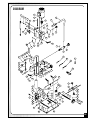
1
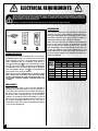
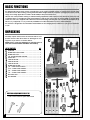
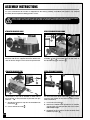
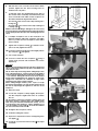
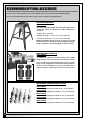
SETUP & OPERATION MANUAL
FEATURES
Heavy duty cast-iron head, column and
base built for steady vibration free performance.
5/8” TILTING HEAD HOLLOW
CHISEL MORTISER
Head slides on precision machined castiron dovetail ways - stroke is controlled by
a gas head-cylinder for smooth operation.
Head tilts up to 30° left or right for angled
mortising, and pivots up to 180° for off
table mortising.
Adjustable head height extends working
capacity by up to 3” (up to 9” under chisel), to accommodate work with taller workpieces.
Equipped with easy to adjust dual depth
stop for complete control of both down
stroke depth and upstroke travel.
Large feed handle with extra long, multiposition arm for better leverage and
increased feed control.
Includes an adjustable workpiece stop,
handwheel controlled clamp and a column mounted hold-down.
Totally enclosed fan cooled (T.E.F.C.) motor
with start capacitor for smooth start-up
and longer running life.
Dust protected on/off switch.
Includes adapter bushings to accommodate both 5/8” and 3/4” sized chisel
shanks.
SPECIFICATIONS
CHISEL CAPACITY
1⁄4” TO 5⁄8” (6 TO 16 MM)
MAXIMUM CHISEL STROKE
9” (228 MM)
DISTANCE FROM FENCE TO CHISEL CENTER
4” (102 MM)
DISTANCE FROM CHISEL TO TABLE
(CHISEL 1/4”)
6” TO 9” (152 MM TO 228 MM)
CHUCK CAPACITY
1⁄2” (13 MM)
FENCE SIZE
14 1/8” X 2 7/8”
TABLE SIZE
13 1/2” X 9” (343 X 230 MM)
BASE SIZE
14 1/8” x 10 3⁄8” (360 x 265 MM)
OVERALL HEIGHT
29” (736 MM)
SPINDLE SPEED
1720 RPM
MOTOR
1/2 HP, 110 V, 1 Ph, 3.8 A
WEIGHT
106 LBS (48 KG)
MODEL
#75-050T M1
VERSION 2_REVISION 2 - January 27/09
© Copyright General® International 01/2009
GENERAL® INTERNATIONAL
8360 Champ-d’Eau, Montreal (Quebec) Canada H1P 1Y3
Telephone (514) 326-1161 • Fax (514) 326-5555 • www.general.ca
THANK YOU
for choosing this General® International model 75-050T M1 5/8”
tilting head hollow chisel mortiser. This mortiser has been carefully tested and inspected before
shipment and if properly used and maintained, will provide you with years of reliable service.
To ensure optimum performance and trouble-free operation, and to get the most from your
investment, please take the time to read this manual before assembling, installing and operating the unit.
The manual’s purpose is to familiarize you with the safe operation, basic function, and features
of this mortiser as well as the set-up, maintenance and identification of its parts and components. This manual is not intended as a substitute for formal woodworking instruction, nor to
offer the user instruction in the craft of woodworking. If you are not sure about the safety of
performing a certain operation or procedure, do not proceed until you can confirm, from
knowledgeable and qualified sources, that it is safe to do so.
Once you’ve read through these instructions, keep this manual handy for future reference.
Disclaimer: The information and specifications in this
manual pertain to the unit as it was supplied from the
factory at the time of printing. Because we are committed
to making constant improvements, General® International reserves the right to make changes to components,
parts or features of this unit as deemed necessary, without prior notice and without obligation to install any
such changes on previously delivered units. Reasonable
care is taken at the factory to ensure that the specifications and information in this manual corresponds with
that of the unit with which it was supplied. However, special orders and “after factory” modifications may render
some or all information in this manual inapplicable to
your machine. Further, as several generations of this model of mortiser and several versions of this manual may
be in circulation, if you own an earlier or later version of
this unit, this manual may not depict your machine
exactly. If you have any doubts or questions contact
your retailer or our support line with the model and serial number of your unit for clarification.
GENERAL® & GENERAL® INTERNATIONAL WARRANTY
All component parts of General®, General® International and Excalibur by General
International ® products are carefully inspected during all stages of production and each unit
is thoroughly inspected upon completion of assembly.
Limited Lifetime Warranty
Because of our commitment to quality and customer satisfaction, General® and General®
International agree to repair or replace any part or component which upon examination,
proves to be defective in either workmanship or material to the original purchaser for the life
of the tool. However, the Limited Lifetime Warranty does not cover any product used for professionnal or commercial production purposes nor for industrial or educational applications.
Such cases are covered by our Standard 2-year Limited Warranty only. The Limited Lifetime
Warranty is also subject to the “Conditions and Exceptions” as listed below.
Standard 2-Year Limited Warranty
All products not covered by our lifetime warranty including products used in commercial,
industrial and educational applications are warranted for a period of 2 years (24 months) from
the date of purchase. General® and General® International agree to repair or replace any
part or component which upon examination, proves to be defective in either workmanship or
material to the original purchaser during this 2-year warranty period, subject to the “conditions
and exceptions” as listed below.
To file a Claim
To file a claim under our Standard 2-year Limited Warranty or under our Limited Lifetime
Warranty, all defective parts, components or machinery must be returned freight or postage
prepaid to General® International, or to a nearby distributor, repair center or other location
designated by General® International. For further details call our service department at 1-888949-1161 or your local distributor for assistance when filing your claim.
Along with the return of the product being claimed for warranty, a copy of the original proof
of purchase and a “letter of claim” must be included (a warranty claim form can also be used
and can be obtained, upon request, from General® International or an authorized distributor)
clearly stating the model and serial number of the unit (if applicable) and including an explanation of the complaint or presumed defect in material or workmanship.
CONDITIONS AND EXCEPTIONS:
This coverage is extended to the original purchaser only. Prior warranty registration is not
required but documented proof of purchase i.e. a copy of original sales invoice or receipt
showing the date and location of the purchase as well as the purchase price paid, must be
provided at the time of claim.
Warranty does not include failures, breakage or defects deemed after inspection by General®
or General® International to have been directly or indirectly caused by or resulting from;
improper use, or lack of or improper maintenance, misuse or abuse, negligence, accidents,
damage in handling or transport, or normal wear and tear of any generally considered consumable parts or components.
Repairs made without the written consent of General® Internationallwill void all warranty.
TABLE OF CONTENTS
Rules for safe operation . . . . . . . . . . . . . . .5
Electrical requirements . . . . . . . . . . . . . . .6
Grounding instructions . . . . . . . . . . . . . . . . . . . . . . .6
Circuit capacity . . . . . . . . . . . . . . . . . . . . . . . . . . . . .6
Extension cords . . . . . . . . . . . . . . . . . . . . . . . . . . . . .6
Identification of main parts
and components . . . . . . . . . . . . . . . . . . . .7
Basic functions . . . . . . . . . . . . . . . . . . . . .8
Unpacking . . . . . . . . . . . . . . . . . . . . . . . . .8
List of contents . . . . . . . . . . . . . . . . . . . . . . . . . . . . . .8
Additional requirements for set up . . . . . . . . . . . . .8
Preparation and installation . . . . . . . . . . . .9
Clean up . . . . . . . . . . . . . . . . . . . . . . . . . . . . . . . . . . .9
Detach the mortiser from its shipping base . . . . . .9
Installation . . . . . . . . . . . . . . . . . . . . . . . . . . . . . . . . .9
Optional stand . . . . . . . . . . . . . . . . . . . . . . . . . . . . . .9
Mounting to a work surface . . . . . . . . . . . . . . . . . . .9
Assembly Instructions . . . . . . . . . . . . .10-12
Attach the workpiece clamp . . . . . . . . . . . . . . . . .10
Attach the workpiece hold down . . . . . . . . . . . . .10
Attach the workpiece stop . . . . . . . . . . . . . . . . . . .10
Install the down feed handle . . . . . . . . . . . . . . . . .10
Install a chisel and bit set . . . . . . . . . . . . . . . . . . . .11
To square the chisel to the fence . . . . . . . . . . . . .12
Basic adjustments & controls . . . . . . . .12-13
Connecting to a power source . . . . . . . . . . . . . . .12
On / off power switch . . . . . . . . . . . . . . . . . . . . . . .13
Setting the depth stop . . . . . . . . . . . . . . . . . . . . . . .13
Basic Operations . . . . . . . . . . . . . . . . .13-14
Additional Adjustments . . . . . . . . . . . . .15-16
Head height adjustment . . . . . . . . . . . . . . . . . . . . .15
Head tilt adjustment . . . . . . . . . . . . . . . . . . . . . . . .15
Head swivel adjustment . . . . . . . . . . . . . . . . . . . . .16
Maintenance . . . . . . . . . . . . . . . . . . . .16-17
Periodic maintenance . . . . . . . . . . . . . . . . . . . . . .16
Sharpening chisels and bits . . . . . . . . . . . . . . . . . .16
Lubrication . . . . . . . . . . . . . . . . . . . . . . . . . . . . . . . .17
Required maintenance . . . . . . . . . . . . . . . . . . . . .17
Tilt index stop adjustment . . . . . . . . . . . . . . . . . . . .17
Recommended optional accessories . . . . .18
Diagram . . . . . . . . . . . . . . . . . . . . . . . . . .19
Parts list . . . . . . . . . . . . . . . . . . . . . . . . .20
Contact info . . . . . . . . . . . . . . . . . . . . . . .22
RULES FOR SAFE OPERATION
To help ensure safe operation, please take a moment to learn the machine’s applications and limitations, as well as potential hazards. General® International disclaims any real or implied warranty and holds itself harmless for any injury that
may result from improper use of its equipment.
1. Do not operate the mortiser when tired, distracted, or
under the effects of drugs, alcohol or any medication
that impairs reflexes or alertness.
12. Always use a clean, properly sharpened chisel and
bit set. Dirty or dull chisels and bits are unsafe and can
lead to accidents.
2. The working area should be well lit, clean and free of
debris.
13. Use suitable work piece support if the work piece does
not have a flat surface.
3. Keep children and visitors at a safe distance when the
mortiser is in operation; do not permit them to operate the mortiser.
14. Do not push or force the chisel and bit into the stock.
The mortiser will perform better and more safely when
working at the rate feed for which it was designed.
4. Childproof and tamper proof your shop and all
machinery with locks, master electrical switches and
switch keys, to prevent unauthorized or unsupervised
use.
15. Avoid working from awkward or off balance positions.
Do not overreach and keep both feet on floor.
5. Stay alert! Give your work your undivided attention.
Even a momentary distraction can lead to serious
injury.
6. Fine particulate dust is a carcinogen that can be hazardous to health. Work in a well-ventilated area and
whenever possible use a dust collector and wear eye,
ear and respiratory protection devices.
7. Do not wear loose clothing, gloves, bracelets, necklaces or other jewelry while the mortiser is in operation.
8. Be sure that adjusting wrenches, tools, drinks and
other clutter are removed from the machine and/or
the table surface before operating.
9. Keep hands well away from the mortising chisel, bit
and all moving parts. Use a hold-down or clamp to
secure the stock, and use a brush, not hands, to clear
away chips and dust.
10. Be sure that the mortising chisel and bit are securely
installed in the chuck before operation.
11. Be sure the mortising bit has gained full operating
speed before beginning to drill.
16. Never leave the machine unattended while it is running or with the power on.
17. Use of parts and accessories NOT recommended by
GENERAL® INTERNATIONAL may result in equipment
malfunction or risk of injury.
18. Never stand on machinery. Serious injury could result
if the tool is tipped over or if the mortiser chisel and bit
are unintentionally contacted.
19. Always disconnect the tool from the power source
before servicing or changing accessories such as
chisel and bit sets, or before performing any maintenance, cleaning, or if the machine will be left unattended.
20. Make sure that the switch is in the “OFF” position before
plugging in the power cord.
21. Make sure the tool is properly grounded. If equipped
with a 3-prong plug, it should be used with a threepole receptacle. Never remove the third prong.
22. Do not use this mortiser for other than its intended
use. If used for other purposes, GENERAL® INTERNATIONAL disclaims any real implied warranty and holds
itself harmless for any injury, which may result from
that use.
5
ELECTRICAL REQUIREMENTS
BEFORE CONNECTING THE MACHINE TO THE POWER SOURCE, VERIFY THAT THE VOLTAGE OF YOUR POWER SUPPLY CORRESPONDS
WITH THE VOLTAGE SPECIFIED ON THE MOTOR I.D. NAMEPLATE. A POWER SOURCE WITH GREATER VOLTAGE THAN NEEDED CAN
RESULT IN SERIOUS INJURY TO THE USER AS WELL AS DAMAGE TO THE MACHINE. IF IN DOUBT, CONTACT A QUALIFIED ELECTRICIAN
BEFORE CONNECTING TO THE POWER SOURCE.
THIS TOOL IS FOR INDOOR USE ONLY. DO NOT EXPOSE TO RAIN OR USE IN WET OR DAMP LOCATIONS.
EXTENSION CORDS
If you find it necessary to use an extension cord with your
machine, use only 3-wire extension cords that have 3prong grounding plug and a matching 3-pole receptacle that accepts the tool’s plug. Repair or replace a
damaged extension cord or plug immediately.
GROUNDING INSTRUCTIONS
In the event of an electrical malfunction or short circuit,
grounding reduces the risk of electric shock. The motor
of this machine is wired for 110V single phase operation
and is equipped with a 3-conductor cord and a 3prong grounding plug
to fit a grounded type receptacle . Do not remove the 3rd prong (grounding pin)
to make it fit into an old 2-hole wall socket or extension
cord. If an adaptor plug is used , it must be attached
to the metal screw of the receptacle.
Note: The use of an adaptor plug is illegal in some
areas. Check your local codes. If you have any doubts
or if the supplied plug does not correspond to your electrical outlet, consult a qualified eletrician before proceeding.
CIRCUIT CAPACITY
Make sure that the wires in your circuit are capable of
handling the amperage draw from your machine, as
well as any other machines that could be operating on
the same circuit. If you are unsure, consult a qualified
electrician. If the circuit breaker trips or the fuse blows
regularly, your machine may be operating on a circuit
that is close to its amperage draw capacity. However, if
an unusual amperage draw does not exist and a
power failure still occurs, contact a qualified technician
or our service department.
6
Make sure the cord rating is suitable for the amperage
listed on the motor I.D. plate. An undersized cord will
cause a drop in line voltage resulting in loss of power
and overheating. The accompanying chart shows the
correct size extension cord to be used based on cord
length and motor I.D. plate amp rating. If in doubt, use
the next heavier gauge. The smaller the number, the
heavier the gauge.
TABLE - MINIMUM GAUGE FOR CORD
TOTAL LENGTH OF CORD IN FEET
110
VOLTS
25
FEET
50 FEET 100 FEET
AMPERE
RATING 220 VOLTS 50 FEET 100 FEET 200 FEET
150 FEET
300 FEET
AWG
------->
------->
10 TO 12 ------->
12 TO 16 ------->
<5
18
16
16
14
6 TO 10
18
16
14
12
16
16
14
12
14
12
* NR
* NR
* NR = Not Recommended
5/8” TILTING HEAD HOLLOW CHISEL MORTISER
75-050T M1
IDENTIFICATION OF MAIN PARTS AND COMPONENTS
LEFT SIDE VIEW
DOWNFEED HANDLE
MOTOR
ON/OFF SWITCH
GAS HEAD-CYLINDER
DEPTH STOP
FENCE
BASE
FENCE LOCKING LEVERS
WORKPIECE STOP
WORKPIECE CLAMP
WORKPIECE HOLD-DOWN
CHISEL AND BIT
CHISEL LOCKING LEVER
SLIDE PLATES
RIGHT SIDE VIEW
REAR VIEW
CHUCK
CHUCK KEY AND HOLDER
RATCHET LEVERS
STOP PIN
7
BASIC FUNCTIONS
This tilting head hollow chisel mortiser is designed to cut 90° and/or angled mortises in solid wood as well as other
wood based stock.With its tilting, pivoting and extendable height head, the 75-050TM1 is designed to tackle a wide
range of mortising applications suited to both hobbyist and professional users.
Ideal for use in any furniture making or cabinet making applications that require mortise and tenon joinery, the unit
is supplied with a set of 4 different sized chisel and bits to help the user cut mortises of varying widths to suit the application. The unit is also supplied with 2 different sized chisel bushings, allowing the user to install chisel and bit sets of
either 5/8" (4 supplied) or 3/4" (commonly available from other after-market sources) shank diameter.
This mortiser is designed to acommodate chisel and bit set sizes ranging from a minimum of 1/4" up to a maximum
of 5/8".
UNPACKING
Carefully unpack and remove the mortiser and its components from the box and check for damaged or missing items as per the list of contents below.
NOTE: Please report any damaged or missing items to
your General International distributor immediately.
LIST OF CONTENTS
QTY
MORTISER.......................................................................1
WORKPIECE HOLD-DOWN ............................................1
WORKPIECE STOP ..........................................................1
3/4” SHANK BUSHING ADAPTER....................................1
CHUCK KEY....................................................................1
3 MM ALLEN KEY ...........................................................1
4 MM ALLEN KEY ...........................................................1
5 MM ALLEN KEY ...........................................................1
WORKPIECE CLAMP ......................................................1
1/4” - 6 MM CHISEL AND BIT.........................................1
5/16” - 8 MM CHISEL AND BIT.......................................1
3/8” - 10 MM CHISEL AND BIT.......................................1
1/2” - 13 MM CHISEL AND BIT.......................................1
HEX HEAD BOLT .............................................................2
FLAT WASHER..................................................................2
ADDITIONAL REQUIREMENTS FOR SET UP
• 13 & 17 mm socket or open end wrench
or
8
PREPARATION AND INSTALLATION
SERIOUS PERSONAL INJURY COULD OCCUR IF YOU CONNECT THE MACHINE TO THE POWER SOURCE BEFORE YOU HAVE COMPLETED THE INSTALLATION AND ASSEMBLY STEPS. DO NOT CONNECT THE MACHINE TO THE POWER SOURCE UNTIL INSTRUCTED
TO DO SO.
CLEAN UP
Clean all rust protected surfaces by rubbing with a rag dipped in kerosene, mineral spirits or paint thinner. (Dispose
of potentially flammable solvent-soaked rags according to manufacturer’s safety recommendations.) Avoid rubbing any painted surfaces, as many solvent-based products will remove paint.
To prevent rust, apply a light coating of paste wax or use regular applications of any after-market surface protectant or rust inhibitor.
DETACH THE MORTISER FROM ITS SHIPPING BASE
INSTALLATION
Unscrew the 4 shipping bolts
using a 13 mm socket
or open end wrench, then remove the mortiser from
the protective plywood shipping base.
This machine should be installed and operated only
on a flat, sturdy and stable surface able to support the
weight of the machine (92 lbs - 42 kg) and the workpiece with ease.
NOTE: Never install the machine over the edge of a table
or workbench
.
OPTIONAL STAND
MOUNTING TO A WORK SURFACE
HEX HEAD BOLT
FLAT WASHERS
LOCK WASHER
HEX NUT
If you prefer an optional stand, item 75-045 Heavy-duty
open stand
is available from your local General
International dealer.
NOTE: For use with this machine, the use of a plywood (or
other) platform (not supplied) is required to cover the opening in the top of the stand. The platform must be bolted to
the stand through the mounting holes
.
If a permanent shop placement is practical, consider
drilling matching through holes in the mounting surface
of your workbench or stand’s platform to bolt the mortiser in place using hex bolts, flat washers, lock washers
and hex nuts
(fasteners not included), in the assembly order shown in .
FOR YOUR SAFETY IT IS ESSENTIAL THAT THE MORTISER DOES NOT ROCK OR TIP DURING OPERATION. MAKE SURE THAT THE
MORITSER IS FIRMLY SECURED TO THE WORK SURFACE OR STAND’S PLATFORM AND THAT THERE IS NO ROCKING, TIPPING OR
CHATTERING.
9
ASSEMBLY INSTRUCTIONS
For your convenience this mortiser is shipped from the factory partially assembled and requires only minimal
assembly and set up before being put into service.
SERIOUS PERSONAL INJURY COULD OCCUR IF YOU CONNECT THE MACHINE TO THE POWER SOURCE BEFORE YOU HAVE COMPLETED THE ASSEMBLY STEPS. DO NOT CONNECT THE MACHINE TO THE POWER SOURCE UNTIL INSTRUCTED TO DO SO.
ATTACH THE WORKPIECE CLAMP
ATTACH THE WORKPIECE HOLD DOWN
CLOSE UP
Attach the workpiece clamp assembly to the front of
the base with the two supplied hex bolts and flat washers as shown, using a 13 mm socket or open wrench.
Separate the two parts of the workpiece hold down
assembly
then re-assemble them on both sides of
the dovetail way
as shown in .
ATTACH THE WORKPIECE STOP
INSTALL THE DOWN FEED HANDLE
The workpiece stop can be installed on either side of
the mortiser
to suit your needs or personal work preferences.
The four holes in the down feed shaft
allow you to
reposition the handle in the holes for better comfort
and convenience.
1. Thread the workpiece stop into the threaded hole
in the base .
1. Loosen the lock knob
2. Secure with the lock nut
.
.
2. Remove the handle and reposition it as needed,
choosing the hole that provides the most comfortable handle angle.
3. Re-tighten the lock knob to secure the down feed
handle in position .
10
INSTALL A CHISEL AND BIT SET
TURN OFF AND UNPLUG THE MORTISER FROM THE
POWER SOURCE BEFORE PERFORMING ANY MAINTENANCE, ADJUSTMENTS OR BIT CHANGES.
CHISEL AND BIT TIPS ARE VERY SHARP – HANDLE WITH
CARE. TO AVOID PERSONAL INJURY USE A PIECE OF
CARDBOARD, PLASTIC OR OTHER MATERIAL BETWEEN
YOUR FINGER AND THE TIP OF THE BIT WHENEVER HOLDING OR HANDLING THE CHISEL AND BIT BY THE TIP.
This unit is supplied with a set of four different sized chisel and bits to help the user cut mortises of varying
widths to suit the application.
1/2”
3/8”
5/16”
1/4”
1. Select the appropriate size of chisel and bit.
The unit is also supplied with 2 different sized chisel
support bushing adapters allowing the user to install
chisel and bit sets of either 5/8" or 3/4" shank diameter, to accommodate bit sizes (some of which are
available as optional accessories) ranging from a minimum of 1/4" up to a maximum of 5/8”:
NOTE: The 5/8” shank diameter bushing is already intalled
at the factory .
3. Loosen either of the two lock knobs
on the chuck
cover and slide the corresponding slide plate out of
the way .
4. Insert the supplied chuck key
and turn counterclockwise to open the chuck jaws and allow a drill
bit to fit in.
2. Select the appropriate bushing and, if not already
installed, unscrew and remove the locking lever
then slip the bushing into the quill assembly as
shown, .
5. With a piece of plastic, carboard or wood held
between the tip of the bit and your finger,
install the chisel and bit with the chip clearing
slot facing either left or right
and tighten the
bit in the chuck so that the tip of the bit juts out
approximately 1/16" to 3/16" (2 mm to 5 mm) from
the tip of the chisel .
6. While still holding the chisel in place, tighten the locking lever
to secure the chisel in the bushing.
NOTE: Do not overtighten the locking lever as this can damage your mortiser.
11
TO SQUARE THE CHISEL TO THE FENCE
1. Lower the head to its maximum
.
2. Place a piece of taller stock (minimum 3”) against
the fence .
NOTE: Make sure you are using a piece of planed and
squared stock that has an even thickness.
3. Loosen the fence locking levers
and slowly
advance the fence with the piece of wood towards
the chisel.
If the face of the chisel sits flush against the stock
the
chisel is square. Tighten the chisel locking lever and
proceed with normal operation.
If the chisel does not sit flush:
1. Loosen the chisel lock lever
and manually turn
the chisel
until its face sits flush against the stock.
2. Lock the lever to secure the chisel in position.
BASIC ADJUSTMENTS & CONTROLS
CONNECTING TO A POWER SOURCE
TO REDUCE THE RISK OF SHOCK OR FIRE DO NOT OPERATE THE UNIT WITH A DAMAGED POWER CORD OR PLUG.
REPLACE DAMAGED CORD OR PLUG IMMEDIATELY.
TO AVOID UNEXPECTED OR UNINTENTIONAL START-UP, MAKE SURE THAT THE POWER SWITCH IS IN THE OFF POSITION BEFORE CONNECTING TO A POWER SOURCE.
Once the assembly steps have been completed and
the unit is safely secured to a work surface, uncoil the
power cord and plug the power cord into an appropriate outlet. Refer back to the section entitled “ELECTRICAL REQUIREMENTS” and make sure all requirements
and grounding instructions are followed. When mortising operations have been completed unplug the mortiser from the power source.
12
SWITCH OFF
ON/OFF POWER SWITCH
CLOSE UP
VERIFY ALL FOLLOWING CHECK POINTS BEFORE
TURNING ON THE MORTISER. FAILURE TO COMPLY
CAN RESULT IN SERIOUS INJURIES.
•
MAKE SURE THE TWO SLIDE PLATES OF THE CHUCK COVER
ARE CLOSED AND THEIR LOCK KNOBS ARE TIGHTENED
SECURELY.
•
MAKE SURE THE CHISEL AND BIT ARE PROPERLY INSTALLED
AND THAT THE BIT CHUCK AND CHISEL LOCK LEVER ARE
TIGHTENED SECURELY.
•
WHEN THE MORTISER IS RUNNING CHECK TO SEE IF IT RUNS
WITHOUT VIBRATION OR SHAKING.
The mortiser is equipped with a rocker style ON/OFF dust-proof switch located on the front left hand side of the mortiser head.
-
To start the mortiser, push on the upper portion of the switch
-
To stop the mortiser, push on the lower portion of the switch
;
.
SETTING THE DEPTH STOP
Transfer a reference line showing the desired depth of cut onto the front face of the workpiece and then set the
depth stop as follows:
1.
Lower the chisel to the bottom of your depth reference line
then adjust the depth stop
against the stop plate
as shown to prevent the
chisel from lowering any further.
NOTE: As a time saving convenience, the upper stop
can be set to control the upward travel of the head. This
feature allows you to save time by raising the bit only
enough to clear the workpiece and allow you to reposition
the workpiece without having to raise the head to its maximum.
BASIC OPERATIONS
1.
Layout and mark workpieces for the mortises to be
cut.
2.
Install the appropriate chisel and bit in the chuck.
3.
Place the stock on the table against the fence
4.
Set the depth stop.
5.
Loosen the fence locking levers
and adjust the
fence until the workpiece is positioned with the
mortise to be cut centered on the chisel .
.
NOTE: If necessary, lower the chisel onto the workpiece to
make sure the layout lines of the mortise are aligned with
the bit.
13
6.
With the fence now set to the correct front to back
position, tighten the two fence locking levers to
hold the fence in place.
7.
So that the chips are discharged into the part of
the mortise which is already cut, and that the part
to be cut remains well visible, set the workpiece on
the table with the bit aligned with either:
-
The left end of the mortise if the chip clearing slot is
facing left ;
-
The right end of the mortise if the chip clearing slot
is facing right ;
NOTE: To avoid overheating or damage to the chisel or bit,
do not position the slot against the blind end of the mortise
as this would prevent the chips from discharging from the
chisel.
8. If multiple workpieces are to be mortised in an
identical manner, adjust the workpiece stop
to
allow to position the next workpiece at the exact
same location.
9.
Tighten the workpiece clamp
to hold the workpiece securely against the fence.
10. Lower the workpiece hold down until slightly above
the workpiece
and tighten.
11. Turn on the machine.
12. Lower the chisel into the workpiece
using a
steady even pressure until it bottoms out on the
depth stop.
FEED RATE:
NOTE: To prevent burning of the tip of the bit, a steady feed
rate is required. The machine may stall or slow down if the
feed rate is too fast
TIP: To allow chips to discharge when cutting deeper mortises or through mortises, cut the mortise to its full depth in
several steps, by backing off periodically at roughly 3/8”
– 1/2” intervals. Raising the bit back out of the mortise
briefly, before plunging back in, allows the chips to discharge more easily and can contribute to longer chisel
and bit life and cleaner sharper mortises.
When cutting through mortises, place a piece of scrap
wood under the workpiece to help prevent tear-out as the
bit cuts its way through the opposite or exit face of the
workpiece.
13. Raise the chisel.
14. Loosen the workpiece clamp slightly, and reposition the workpiece against the fence to continue
the cut.
TIP: For added convenience and time savings when cutting longer mortises, optional rollers, item 75-055 (available from your General® International dealer) can be
used instead of the workpiece clamp, allowing you to
“roll” the workpiece left or right
as needed to continue
the next cut for the mortise slot.
15. Re-tighten the workpiece clamp.
16. Continue cutting the mortise.
17. Repeat to complete the mortise overlapping each
cut slightly .
18. Test the fit of your tenon in the mortise
if needed.
14
. Re-adjust
ADDITIONAL ADJUSTMENTS
For special applications such as taller workpieces (requiring off table mortising) or for angled mortises, the following machine adjustments can also be made.
MAKE SURE THE MORTISER HAS BEEN TURNED OFF AND UNPLUGGED FROM THE POWER SOURCE BEFORE PERFORMING ANY
ADJUSTMENTS.
HEAD HEIGHT ADJUSTMENT
To raise the height of the head and extend the working capacity of the mortiser (if needed) by up to 3”:
REAR VIEW
3” max
1. Loosen the two ratchet levers
2.
Slightly tighten the ratchet lever
.
.
3.
Manually pull the head 3” up (approx.)
.
4.
Loosen ratchet lever
and tighten ratchet levers
to secure the head in position.
HEAD TILT ADJUSTMENT
The head can be tilted to any angle from 0° to 30° to the
left or right, to allow for bevel (or angle) mortise cutting.
1.
While holding the head, loosen the two bolts
using a 17 mm wrench.
-
,
To set the head 30° left:
Tilt the head towards the left until the tilting
bracket rests against the left 30° stop .
-
To set the head 30° right:
Pull the
towards
against
the stop
-
stop pin
out, then tilt the head
the right until the tilting bracket rests
the 30° right stop
, then release
pin.
To set the head back to 0°:
Pull the stop pin
out, then tilt the head
towards the center until the tilting bracket rests
against the 0° stop
, then release the stop
pin .
-
To set the head to any other angle:
To use a setting other than 0° or 30°, refer to the
head tilt angle indicator
to set the angle of
the head to the desired position.
2.
Re-tighten the two bolts
position.
to secure the head in
15
HEAD SWIVEL ADJUSTMENT
For off-table work, for example with taller workpieces, the
entire head of the mortiser can be swivelled up to 180° left
or right. To swivel the head:
1.
To avoid damaging the chisel and bit or the fence,
remove the chisel and bit and move the fence as far
as possible towards the front before swivelling the
head.
2.
Loosen the two ratchet levers
3.
Tighten the ratchet lever
desired position.
4.
Loosen ratchet lever
and tighten ratchet levers
to secure the head in position.
.
then swivel the head to the
MAINTENANCE
MAKE SURE THE MORTISER HAS BEEN TURNED OFF AND UNPLUGGED FROM THE POWER SOURCE BEFORE PERFORMING ANY
MAINTENANCE.
PERIODIC MAINTENANCE
•
Keep the machine clean and free of dust, and woodchips. Vacuum or brush off any loose debris and wipe
down the machine and the table occasionally with a damp rag.
•
An occasional light coating of paste wax can help protect the table surface and reduce workpiece friction.
Ask your local distributor for suggestions on aftermarket surface cleaners and protectants based
on what is readily available in your area. (Avoid using silicon based products that may affect wood finishing
products such as oil, solvent or water-based stains, varnishes and lacquers.)
•
Periodically inspect the power cord and plug for damage. To minimize the risk of electric shock or fire, never
operate the mortiser with a damaged power cord or plug. Replace a damaged power cord or plug at the first
visible signs of damage.
•
Periodically inspect chisel and bits for signs of visible damage. Replace a chipped or damaged chisel or bit
immediately.
SHARPENING CHISELS AND BITS
Working with properly sharpened chisel and bits sets will greatly increase the quality of your work and allow you to
obtain clean, crisply cut mortises with minimal effort. With use over time chisels and bits will need to be re-sharpened.
The frequency of use, type of workpiece material and the size and depth of the mortises you cut will affect how often
or infrequently re-sharpening will be required.
You will find there are a variety of aftermarket sharpening tools made by third party sources that are available on
the market for both the chisels and the bits for your mortiser. Your local distributor or tool retailer will be able to
advise you of any sharpening tool options based on what
is readily available in your area.
Take note that chisels should only be sharpened on their
inside edges as any material removed from the outside
edge will affect and change the overall dimensions of the
chisel. An example of a typical chisel sharpening cone is
shown in
. Such cones are usually made available in
sets or individually by size and should be matched to the
size of the chisel – your local tool distributor or sharpening
supplies specialist will be able to advise you further. For
best results follow the instructions supplied with the sharpening tool or accessory being used.
16
LUBRICATION
REAR VIEW
Keep the column
and both sides of the dovetail way
well lubricated and free of dust or debris. Clean and
remove dust, debris, and old lubricant as needed
depending on frequency of use. After cleaning, reapply
a verly light coating of lubricant.
NOTE: Use any all-purpose oil, available at any hardware store).
REQUIRED MAINTENANCE
With use and normal wear over time, the motor assembly may loosen slightly. If you notice abnormal noise
or vibrations, tighten the cap screws
(accessible
behind the slide plates on both sides of the chuck),
using the supplied 5 mm allen key.
With use over time, some slight play may develop in
head on the dovetail way due to wear. To eliminate play
between the head and the dovetail way, loosen the lock
nuts , and adjust the individual set screws as needed.
Re-tighten the lock nut(s) once the adjustment has been
completed.
NOTE: Adjust only enough to eliminate play – do not over
tighten as this can stiffen or restrict head travel, requiring
more effort to complete the feed stroke and cause premature wear of the dovetail way.
TILT INDEX STOP ADJUSTMENT
The 0°, 30° right and 30° left index stops are factory set. However, with use and vibration over time, they eventually
may need minor adjustments.
If the left 30° index stop
needs to be adjusted:
If the right 30° stop
or 0° stop
needs to be adjusted:
1.
Loosen the lock nut
using a 10 mm wrench.
1.
Loosen the lock nut using a 10 mm wrench.
2.
Using the supplied 3 mm Allen key, adjust the set
screw
in or out until the indicator points toward
30° on the angle scale, then re-tighten the lock nut.
2.
Using the supplied 3 mm Allen key, adjust the set
screw
in or out until the indicator points to 30° or
0°, respectively, then re-tighten the lock nut.
17
RECOMMENDED OPTIONAL ACCESSORIES
Here are some of the optional accessories available from your local General International dealer.
For more information about our products, please visit our website at www.general.ca
HEAVY-DUTY OPEN STAND
ITEM # 75-045
Heavy duty adjustable height, flared steel stand. Wide stance
design with sturdy cross-bracing for stable vibration-free
operation.
- Height: 30 5/8” (778 mm)
- Dimensions at top: 13 1/4” x 18 1/2” (336 x 470 mm)
- Dimensions at feet: 26 1/2” x 33 1/4” (673 x 845 mm)
NOTE: Top opening measures are 9 1/4” x 12 3/4”. For use with
this machine, the use of a plywood (or other) platform (not supplied) is required to cover the opening in the top of the stand.
MORTISING TABLE ROLLERS (2)
ITEM # 75-055
For added convenience and time savings when cutting
longer mortises. Use rollers instead of the workpiece clamp.
No more clamp ing and unclamping after each cut! Simply
butt the rollers up against the workpiece keeping it tight to
the fence; after completing a cut,“roll” the workpiece left or
right as needed to continue the next cut for the mortise slot.
REPLACEMENT/OPTIONAL CHISEL & BIT SETS
ITEM # 70-910
1⁄4” (6 mm) mortising chisel & bit set, 5⁄8” (16 mm) shank
ITEM # 70-920
5/16” (8 mm) mortising chisel & bit set, 5⁄8” (16 mm) shank
ITEM # 70-930
3/8” (10 mm) mortising chisel & bit set, 5⁄8” (16 mm) shank
ITEM # 70-940
1/2” (13 mm) mortising chisel & bit set, 5⁄8” (16 mm) shank
ITEM # 70-950
5/8” (16 mm) mortising chisel & bit set, 5⁄8” (16 mm) shank
18
DIAGRAM
58
33
05
19
41
06
38
39
18
44
40
42
43
37
53
36
03
52
35N
34
52
55
46
21
03
53
13
14
15
62
12
61
20
81
12-1
46-1
82
83
22
11
60
10
17
09
59
16
80
17-1
12
23
24
25
63
04
64
26N
06
05
28
65
50
29
48
68
66
69
67
26-1N
74
75
76
49
70-1N
77
56
73
71
72
51
31
02
32
07
78
43
27
30
43
08
56
57
01N
70
79
54
45N
19
PARTS LIST
75-050T M1
PART N0.
DESCRIPTION
75050T-01N
75050T-02
75050T-03
75050T-04
75050T-05
75050T-06
75050T-07
75050T-08
75050T-09
75050T-10
75050T-11
75050T-12
75050T- 12-1
75050T-13
75050T-14
75050T-15
75050T-16
75050T-17
75050T -17-1
75050T-18
75050T-19
75050T-20
75050T-21
75050T-22
75050T-23
75050T-24
75050T-25
75050T-26N
75050T-26-1N
75050T-27
75050T-28
75050T-29
75050T-30N
75050T-31
75050T-32
75050T-33
75050T-34
75050T-35N
75050T-36
75050T-37
75050T-38
75050T-39
75050T-40
75050T-41
75050T-42
75050T-43
BASE
SET SCREW 5/16 X 3/8
WASHER 1/4
RATCHET LEVER M8
SCREW M8
LOCK WASHER 3/8
WASHER 5/16
HEX HEAD BOLT 5/16 X 1
DEPTH STOP BAR
LOCK KNOB 5/16 X 3/4
ADJUSTING SLEEVE
LOCK KNOB 5/16
SET SCREW 5/16 X 3/8
STOP BAR SUPPORT POST
SCREW 3/16
CORD CLAMP 1/4
COLUMN
"C" RING 15
"C" RING 20
HANDLE GRIP
DOWNFEED HANDLE
DOWNFEED SHAFT
KEY
GEAR
LOCK KNOB 3/8 X 90
HOLD DOWN CLAMP ARM
HOLD DOWN CLAMP ARM
FENCE
SLIDE BAR
STOP BAR BLOCK
SCREW 1/4 X 5/8
VISE PLATE
VISE MOUNT BRACKET
THREADED ROD
HANDWHEEL
GAS SPRING
CAP SCREW 1/4 X 1
MACHINE HEAD
STOP PLATE
CAP SCREW 1/4 X 3/4
CAP SCREW 1/4 X 5/8
RACK
SLIDE PLATE
MOTOR
SET SCREW 5/16 X 3/4
HEX NUT 5/16
NOTES
20
QTY
1
1
2
2
2
2
2
2
1
1
2
2
2
2
1
1
1
1
1
1
1
1
1
1
1
1
1
1
1
1
1
1
1
1
1
1
4
1
1
2
2
1
1
1
3
3
PART N0.
DESCRIPTION
75050T-44
75050T-45N
75050T-46
75050T-46-1
75050T-48
75050T-49
75050T-50
75050T-51
75050T-52
75050T-53
75050T-54
75050T-55
75050T-56
75050T-57
75050T-58
75050T-59
75050T-60
75050T-61
75050T-62
75050T-63
75050T-64
75050T-65
75050T-66
75050T-67
75050T-68
75050T-69
75050T-70
75050T-70-1N
75050T-71
75050T-72
75050T-73
75050T-74
75050T-75
75050T-76
75050T-77
75050T-78
75050T-79
75050T-80
75050T-81
75050T-82
75050T-83
70-910
70-920
70-930
70-940
CHUCK X 13 MM
SCALE
CHISEL BUSHING (5/8 SHANK)
CHISEL BUSHING (3/4 SHANK)
STOP BAR (SHORT)
STOP BAR (LONG)
LOCK KNOB
LOCK KNOB
SLIDE PLATE (CHUCK COVER)
LOCK KNOB 1/4
BOLT M 8
RATCHET LEVER
NUT 5/16
HANDLE
SWITCH
CHUCK KEY HOLDER
SCREW 3/16
GEAR COVER
SCREW
RATCHET LEVER 5/16
RATCHET LEVER M6
COLUMN EXTENSION POST
COLUMN MOUNT BRACKET
SET SCREW
LABEL
ANGLE SCALE
SET SCREW
SET SCREW M6X25
HEX HEAD BOLT
FLAT WASHER
TILT STOP BRACKET
FLAT WASHER
HEX HEAD BOLT
SCREW
POINTER
STOP PIN
NUT
CHUCK KEY
3 MM ALLEN KEY
4 MM ALLEN KEY
5 MM ALLEN KEY
1/4” - 6 MM CHISEL AND BIT (NOT SHOWN)
5/16” - 8 MM CHISEL AND BIT (NOT SHOWN)
3/8” - 10 MM CHISEL AND BIT (NOT SHOWN)
1/2” - 13MM CHISEL AND BIT (NOT SHOWN)
QTY
1
1
1
1
1
1
1
1
2
2
2
1
2
1
1
1
1
1
2
2
1
1
1
2
2
1
2
1
2
4
1
2
2
1
1
1
1
1
1
1
1
1
1
1
1
Notes
21
MODEL 75-050T M1
8360 Champ-d’Eau, Montreal (Quebec) Canada H1P 1Y3
Fax: (514) 326-5565 -
Tel.: (514) 326-1161
Fax: (514) 326-5555 -
Parts & Service /
Order Desk
[email protected]
www.general.ca
IMPORTANT
When ordering replacement parts, always give the model number, serial number of the machine and
part number. Also a brief description of each item and quantity desired.