1
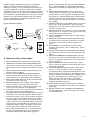
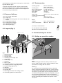
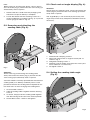
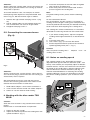
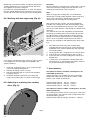
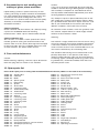
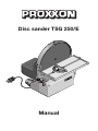
Disc sander TSG 250/E
Manual
Operating Instructions Disc sander TSG 250/E
1.
2.
3.
3.1.
4.
4.1.
4.2.
4.3.
5.
5.1.
5.2.
5.3.
5.4.
5.5.
6.
6.1.
6.2.
6.3.
7.
8.
9.
10.
11.
Introduction ………………………………………………………………………………………………………………… 2
GROUNDING INSTRUCTIONS ………………………………………………………………………………………… 2
General safety instructions ………………………………………………………………………………………………… 3
Additional safety instructions for sander ………………………………………………………………………………… 4
Description of disc sander TSG 250/E …………………………………………………………………………………… 4
Scope of delivery:…………………………………………………………………………………………………………… 5
Legend (Fig. 1) ……………………………………………………………………………………………………………… 5
Technical data ……………………………………………………………………………………………………………… 5
Commissioning the device ………………………………………………………………………………………………… 5
Setting up your disc sander: ……………………………………………………………………………………………… 5
Removing and attaching the sanding table (Fig. 3): …………………………………………………………………… 6
Check and set angle display (Fig. 4): …………………………………………………………………………………… 6
Setting the sanding table angle (Fig. 5): ………………………………………………………………………………… 6
Connecting the vacuum cleaner (Fig. 6): ………………………………………………………………………………… 7
Working with the disc sander TSG 250/E: ……………………………………………………………………………… 7
Notes on sanding speed …………………………………………………………………………………………………… 7
Working with the angle stop (Fig. 8):……………………………………………………………………………………… 8
Adhering or replacing the sanding discs (Fig. 9): ……………………………………………………………………… 8
Accessories: ………………………………………………………………………………………………………………… 8
Accessories for wet sanding and cutting of glass, stone and tiles: …………………………………………………… 9
Care and maintenance …………………………………………………………………………………………………… 9
Spare parts list ……………………………………………………………………………………………………………… 9
Exploded drawing ………………………………………………………………………………………………………… 11
1. Introduction
2. Grounding instructions
Dear Customer!
1. All grounded, cord-connected tools:
The use of these instructions
In the event of a malfunction or breakdown, grounding
provides a path of least resistance for electric current to
reduce the risk of electric shock. This tool is equipped
with an electric cord having an equipment-grounding
conductor and a grounding plug. The plug must be
plugged into a matching outlet that is properly installed
and grounded in accordance with all local codes and
ordinances. Do not modify the plug provided -- if it will
not fit the outlet, have the proper outlet installed by a
qualified electrician.
Improper connection of the equipment-grounding conductor can result in a risk of electric shock. The conductor with insulation having an outer surface that is green
with or without yellow stripes is the equipment-grounding conductor. If repair or replacement of the electric
cord or plug is necessary, do not connect the equipment-grounding conductor to a live terminal. Check with
a qualified electrician or service personnel if the grounding instructions are not completely understood, or if in
doubt as to whether the tool is properly grounded.
Use only 3-wire extension cords that have 3prong
grounding plugs and 3pole receptacles that accept the
tool's plug.
• makes it easier to become acquainted with the device,
• prevents malfunctions due to improper handling, and
• increases the service life of your device.
Always keep these instructions close to hand.
Only operate this device with exact knowledge of it and
comply with the instructions.
PROXXON will not be liable for the safe function of the
device for:
• handling that does not comply with the usual intended
use,
• other application uses that are not stated in the
instructions,
• disregard of the safety regulations,
You will not have any warranty claims for:
• operating errors,
• lack of maintenance.
For your safety, please comply with the enclosed safety
regulations without fail.
Only use original PROXXON spare parts.
All rights reserved for further developments within the
meaning of technical progress. We wish you much success with the device.
Repair or replace damaged or worn cord immediately.
2. Grounded, cord-connected tools intended for use on
a supply circuit having a nominal rating less than
150 volts:
This tool is intended for use on a circuit that has an outlet that looks like the one illustrated in Sketch A in Figure 10. The tool has a grounding plug that looks like the
-2-
plug illustrated in Sketch A in Figure 10. A temporary
adapter, which looks like the adapter illustrated in
Sketches B and C, may be used to connect this plug to
a 2-pole receptacle as shown in Sketch B if a properly
grounded outlet is not available. The temporary adapter
should be used only until a properly grounded outlet can
be installed by a qualified electrician. The green-colored
rigid ear, lug, and the like, extending from the adapter
must be connected to a permanent ground such as a
properly grounded outlet box.
Fig. 10: Grounding methods
METAL SCREW
COVER OF GROUNDED
OUTLET BOX
GROUNDING
PIN
<B>
<A>
ADAPTER
<C>
GROUNDING
MEANS
GROUNDING
PIN
<D>
3. General safety instructions
1. KEEP GUARDS IN PLACE and in working order.
2. REMOVE ADJUSTING KEYS AND WRENCHES.
Form habit of checking to see that keys and adjusting wrenches are removed from tool before turning it
on.
3. KEEP WORK AREA CLEAN. Cluttered areas and
benches invite accidents.
4. DON'T USE IN DANGEROUS ENVIRONMENT.
Don't use power tools in damp or wet locations, or
expose them to rain. Keep work area well lighted.
5. KEEP CHILDREN AWAY. All visitors should be kept
safe distance from work area.
6. MAKE WORKSHOP KID PROOF with padlocks,
master switches, or by removing starter keys.
7. DON'T FORCE TOOL. It will do the job better and
safer at the rate for which it was designed.
8. USE RIGHT TOOL. Don't force tool or attachment to
do a job for which it was not designed.
9. USE PROPER EXTENSION CORD. Make sure your
extension cord is in good condition. When using an
extension cord, be sure to use one heavy enough to
carry the current your product will draw. An undersized cord will cause a drop in line voltage resulting
in loss of power and overheating. Table 1 shows the
correct size to use depending on cord length and
nameplate ampere rating. If in doubt, use the next
heavier gage. The smaller the gage number, the
heavier the cord.Exception No. 1: The reference to
the table and the table itself may be omitted if a
statement indicating the appropriate gage and
length is incorporated into the instruction.Exception
No. 2: The information regarding extension cords
need not be provided for a permanently connected
tool.
10. WEAR PROPER APPAREL. Do not wear loose
clothing, gloves, neckties, rings, bracelets, or other
jewelry which may get caught in moving parts. Nonslip footwear is recommended. Wear protective hair
covering to contain long hair.Exception: The reference to gloves may be omitted from the instructions
for a grinder.
11. ALWAYS USE SAFETY GLASSES. Also use face or
dust mask if cutting operation is dusty. Everyday
eyeglasses only have impact resistant lenses, they
are NOT safety glasses.
12. SECURE WORK. Use clamps or a vise to hold work
when practical. It's safer than using your hand and it
frees both hands to operate tool.
13. DON'T OVERREACH. Keep proper footing and balance at all times.
14. MAINTAIN TOOLS WITH CARE. Keep tools sharp
and clean for best and safest performance. Follow
instructions for lubricating and changing accessories.
15. DISCONNECT TOOLS before servicing; when
changing accessories, such as blades, bits, cutters,
and the like.
16. REDUCE THE RISK OF UNINTENTIONAL STARTING. Make sure switch is in off position before plugging in.
17. USE RECOMMENDED ACCESSORIES. Consult
the owner's manual for recommended accessories.
The use of improper accessories may cause risk of
injury to persons.
18. NEVER STAND ON TOOL. Serious injury could
occur if the tool is tipped or if the cutting tool is unintentionally contacted.
19. CHECK DAMAGED PARTS. Before further use of
the tool, a guard or other part that is damaged
should be carefully checked to determine that it will
operate properly and perform its intended function -check for alignment of moving parts, binding of moving parts, breakage of parts, mounting, and any
other conditions that may affect its operation.
A guard or other part that is damaged should be
properly repaired or replaced.
20. DIRECTION OF FEED. Feed work into a blade or
cutter against the direction of rotation of the blade or
cutter only.
21. NEVER LEAVE TOOL RUNNING UNATTENDED.
TURN POWER OFF. Don't leave tool until it comes
to a complete stop.
-3-
Table 1: Minimum gage for cord
Effective date for Table 1 changed from November 1, 1995 to November 11, 1996
Ampere Rating
Volts
Total length of cord in feet
120 V
25 ft.
50 ft.
100 ft.
150 ft.
240 V
50 ft.
100 ft.
200 ft.
300 ft.
More Than
Not More Than
0
6
AWG
18
16
16
14
6
10
18
16
14
12
10
12
16
16
14
12
12
16
14
12
Not Recommended
a Only the applicable parts of the Table need to be included. For instance,
a 120-volt product need not include the 240-volt heading.
3.1. Additional safety instructions for
sander
1. Operate only after you have received instruction.
2. Wear proper clothing.
3. Wear face shield, safety glasses, or goggles and
use glass safety guard on grinder.
4. See that the guard is in place.
5. Set tool rest 1/16 inch to 1/8 inch from the wheel.
6. Dress wheel when necessary.
7. Make sure that no one but you is inside the operator's area.
8. Adjust grinder for your job before turning power on
9. Stand to one side of wheel when turning power on.
The wheel may be cracked, causing it to break up.
10. Turn on power after permission is given.
11. Keep hands away from the wheel while it is in
motion
12. Hold work with your hands. Ask permission to grind
small pieces.
13. Use the face of the wheel only
14. Press materials against wheel with correct amount
of pressure.
WARNING:
Some dust created by power sanding, sawing, grinding,
drilling, and other construction activities contains chemicals known to the State of California to cause cancer,
birth defects or other reproductive harm. Some examples of these chemicals are:
• lead from lead-based paints,
• crystalline silica from bricks and cement and other
masonry products, and
• arsenic and chromium from chemically-treated lumber.
Your risk from these exposures varies, depending on
how often you do this type of work. To reduce your
exposure to these chemicals: work in a well ventilated
area, and work with approved safety equipment, such
as those dust masks that are specially designed to filter
out microscopic particles.Use a vacuum cleaner for
-4-
wood dust collection as described in our manual whenever possible.
4. Description of disc sander TSG 250/E
Thank you for choosing the disc sander TSG 250/E. You
now have a precision instrument for sanding long
edges, end sections, radii, mitres, or accurate flat surfaces at right angles and many more things that require
great exactness.
A high-precision manufactured and carefully balanced
sanding disc with dual ball-bearing synchronous belt
drive guarantees excellent running smoothness, precise
true run and lowest wear.
Soft and hard woods, plates, non-ferrous metals or
steel, even plastic, cork, rubber and many other materials can be machined at sanding speeds of approx. 250750 m/min (adjustable).
Installing the liquid cooling system accessory (consisting of cooling container and coolant collection tray)
expands the range of machinable materials even further: Sanding glass, stones or tiles is thus no problem.
The device is suitable for wet sanding.
A clearly laid out table at the rear of the device makes it
easy to pre-select the rotational speed or sanding speed
for the appropriate material.
The high-quality aluminium sanding table can be
adjusted to tilt up by 10° and down by 50°. A scale
makes it easy to read the angle. This also contains the
guide groove of the angle stop that is also included in
the delivery.
It is even possible to accurately refinish small turning
steels, sharpen chisels and knives, re-sand screwdriver
edges, etc. ...
Delivery includes two sanding discs of 80 and 240 grit
each. A silicone film was attached to the sanding disc to
guarantee best sanding disc exchange (e.g. while working with different grits).
A suction connection for the vacuum cleaner makes
sure that sanding dust has no other place to go but in
the vacuum cleaner. This presents the best equipment
for any occurring sanding work.
4.1. Scope of delivery:
1 pc. Disc sander TSG 250/E
1 pc. Angle stop
1 pc. Rubber connecting piece for vacuum cleaner connection
2 pc. Sanding discs 80 grit
2 pc. Sanding discs 240 grit
1 pc. Operating instructions
1 pc. Device packaging
4.3. Technical data
Sanding speed:
820 to 2,460 ft/min
(250 – 750 m/min)
Sanding disc:
Ø 9 27/32" (250 mm)
Max. sanding height: 5 5/16" (135 mm)
Table adjustment:
tilts 10° up, 50° down
Noise level:
72 dB(A)
Vibration:
<= 2.5 m/s²
Work table:
10,83” x 4,13” (275 x 105 mm)
Overall size (without table)
(L x D x H):
10,6” x 11” x 13”
(270 x 280 x 330 mm)
Motor:
Voltage:
Power consumption:
220 – 240 V, 50/60 Hz
200 watt, KB 15 min
Use only in closed rooms!
Do not dispose of the electrical
device in the household waste!
4.2. Legend (Fig. 1)
13 1
15
5
2
16
5. Commissioning the device
14
1
3
5.1. Setting up your disc sander:
4
Fig.1
1.
2.
3.
4.
5.
6.
7.
8.
9.
10.
11.
12.
13.
14.
15.
16.
6 5
3
2
1
8
9
10 12 11
4 6
Speed controller
On/Off switch
Sanding table
Clamping screw angle stop
Angle stop
Scale angle stop
Housing
Mains cable
Connecting piece for vacuum cleaner
Clamping screw of angle adjustment
Scale of angle adjustment
Indicator
Protecting cover
Sanding disc
Mounting connection for cooling system
Connecting piece for coolant hose
5
7
Fig. 2
Note:
When setting up the device, always make sure you
have a level and firm surface! Secure stability is indispensable for working with the device!
Warning !
To avoid injury from unexpected starting or electrical
shock, do not plug the power cord into a power source
receptacle during unpacking and assembly. Never connect the plug to the power source receptacle until the
assembly and adjustment steps are completed, and you
have read and understand the safety and operating
instructions. Make certain the switch is in the off position
before connecting the machine to the power source
receptacle.
-5-
Note:
When setting up and fixing the device, always disconnect the mains plug to prevent the disc from starting up
inadvertently. Risk of injuries!
1. Remove the disc sander from the packaging and
check if the scope of delivery is complete.
2. Fasten the device with the fastening screws to a
sturdy workbench or worktop (see Fig. 2) as per the
master gauge for holes in Fig. 2a.
5.3. Check and set angle display (Fig. 4):
Attention:
Before doing any adjusting work, always disconnect the
mains plug to prevent the disc from starting up inadvertently. Risk of injuries!
The angle display is set accurately by the factory. The
angle stop can be easily readjusted, should this ever be
necessary:
1
5.2. Removing and attaching the
sanding table (Fig. 3):
2
2
14 3
1
3
Fig. 3
Fig. 4
1. Release both clamping screws 1
2. Align work table 2 with an angle to exactly 90° as
shown in Fig. 4
3. Retighten clamping screws 1
4. Release screw 3 slightly and correct the "zero" position of indicator 4 as necessary.
5. Re-tighten screw 3
1
Attention:
Before removing and inserting the sanding table,
always disconnect the mains plug to prevent the disc
from starting up inadvertently. Risk of injuries!
5.4. Setting the sanding table angle
(Fig. 5):
Your TSG 250/E is normally operated with the attached
sanding table (as in delivery condition). But it is also
possible to remove the sanding table if required for certain work tasks or when changing the sanding discs.
1
1. Unscrew Allen screws 1
2. Take off sanding table 2 together with the housing
cover 3
3. To attach, simply insert the sanding table together
with the housing cover back in the normal position
4. Screw Allen screws 1 back in and tighten.
2
1
3
-6-
Fig. 5
Attention:
Before setting the sanding table, always disconnect the
mains plug to prevent the disc from starting up inadvertently. Risk of injuries!
3. Place the work piece on the work table and guide
with sensitivity and little force.
4. Exert more pressure on the work table and less
pressure against the sanding disc.
To chamfer boards or slats, for example, we recommend placing these objects on the pivoted table. Also
refer to Fig. 5a. Set the chamfer angle as follows:
Note:
For good sanding results, please note the following
points:
1. Release the right and left clamping screws 1 (Fig.
5b)
2. Swivel sanding table 2 to the required angle position and check the set value on angle scale 3.
3. Retighten clamping screws 1.
Do not overload the device!
First and foremost, the disc sander is a machine for
sanding accurate angles. Cutting your work piece very
accurately beforehand will make your desired machining
easier and faster while requiring less sanding discs.
5.5. Connecting the vacuum cleaner
(Fig. 6):
The sanding disc rotates anticlockwise. It is therefore
advisable to sand using the left half of the work table.
1. If you will be sanding mitres, adjust the required
sanding table angle beforehand, as described earlier
2. Insert the mains plug
3. Use switch 2 (Fig. 1) to activate the device
4. Set the required rotational speed at the rotational
speed regulating knob (Pos. 1, Fig. 1)
Caution!
Only use perfect sanding discs.
sanding discs in time.
Replace
worn
out
6.1. Notes on sanding speed
3
Fig. 6
1
2
Attention:
Before connecting the vacuum cleaner, always disconnect the mains plug to prevent the disc from starting up
inadvertently. Risk of injuries!
The sanding speed of your TSG 250/E is infinitely
adjustable from approx. 820 to 2,460 ft/min (250 – 750
m/min). This enables you to optimally adjust to different
material features. Please also note that the circumferential speed of the sanding disc is greatest along the outside and decreases towards the centre (see Fig. 7).
General recommendations on selecting the sanding
speed are difficult; it is best you experiment to find out
the correct sanding speed for "your" material or work
piece.
We recommend you always work with the vacuum
cleaner! This not only guarantees clean work but also
reduces the harmful effect of some dusts!
1. Slide rubber adapter 1 onto suction connection 2
2. Insert vacuum cleaner nozzle 3 in rubber adapter 1
3. Switch on vacuum cleaner while working
6. Working with the disc sander TSG
250/E:
Caution!
Safe and accurate work is only possible with careful fastening!
Never leave an activated device unsupervised.
1. Switch on the disc sander.
2. Adjust the rotational speed of the sanding disc with
speed controller 1 (Fig. 1).
Fig. 7
-7-
Empirically, non-ferrous metals and plastic require less
sanding speeds than soft and hard woods; the same
also applies to ceramics and glass.
In conclusion: Recommendations, as said, are difficult:
the right speed depends on the material, contact pressure or abrasive wear and the grit of the sanding discs.
6.2. Working with the angle stop (Fig. 8):
Attention:
Before adhering or changing the sanding discs, always
disconnect the mains plug to prevent the disc from
starting up inadvertently. Risk of injuries!
Note:
When changing the sanding disc, we recommend
removing the sanding table together with the housing
cover. This procedure is explained in the section
"Removing and attaching the sanding table".
Along with your disc sander, your basic equipment
includes two sanding discs with 80 and 240 grit each;
these are easily obtainable spare parts. The sanding
disc of your TSG 250/E is covered with an adhesive silicone film:
This material ensures the completely uncomplicated
exchange of sanding discs because they do not stick
but adhere firmly: Firmly enough to work, but loose
enough to be easily removed later on. Replacing the
discs is thus no problem, either because of wear or
because you need discs with different grits while working.
2
1
Fig. 8
If you will be sanding the ends of thinner strips to mitre,
it is expedient to use the angle stop included in the
scope of delivery.
1. Insert the angle stop (Pos. 5, Fig. 1) with the stop
rail into the designated groove.
2. Release clamping screw 1 (Fig. 8).
3. Set the required angle on scale 2 and re-tighten
clamping screw 1.
4. Guide the desired work piece at the limit stop
against the sanding disc as shown in the image
1. We recommend removing the sanding table
together with the housing cover. This procedure is
explained in the section "Removing and attaching
the sanding table".
2. To change the disc, simply pull it off from the plate.
3. Peel off the rear protective film of the new disc.
4. Press the disc on to the sanding disc evenly and
bubble-free.
5. If necessary, reassemble the sanding table with
housing cover as explained in the section "Removing and attaching the sanding table".
7. Accessories:
Self-adhesive white corundum sanding discs for
TSG 250/E (Ø 250 mm)
Industrial quality. For sanding soft and hard woods,
chipboards, fibre boards, non-ferrous metals, steel,
plastic, cork, rubber and minerals.
Article number 28 970 80 grit
Article number 28 972 150 grit
Article number 28 974 240 grit
6.3. Adhering or replacing the sanding
discs (Fig. 9):
(5 piec.)
(5 piec.)
(5 piec.)
Self-adhesive silicon carbide sanding discs for TSG
250/E (Ø 250 mm)
For sanding non-ferrous metals, steel, glass, GRP, plastic and ceramics. Can also be used in conjunction with
the liquid cooling system.
Article number 28 976, 320 grit, Contents: 5 pieces
Fig. 9
-8-
8. Accessories for wet sanding and
cutting of glass, stone and tiles:
Liquid cooling system as specific accessory for wet
sanding, consisting of coolant container and collection
tray. This enables the machining of glass, stones, tiles
or steel and also bonds sanding dust. The use of
coolant also has a positive effect on the surface quality.
Assembly is absolutely uncomplicated thanks to the
enclosed instructions.
Coolant container
Plastic container with flow release, 39" (100 cm) tubing,
2 spouts for the MBS/E table and mounting
bracket/screws. Holds 1 quart. Article number 28 188
Coolant collection tray
Size 16 17/32" x 12 13/64" x 19/32" (420 x 310 x 15mm).
Includes gasket for sealing the attachment holes of the
machine. With 19 11/16" (50 cm) discharge tube and nipple
for band saw table. The tray is undrilled and may be used
on other machines, too. Article number 28 189
9. Care and maintenance
Caution:
Before cleaning, adjusting, service or repair, disconnect
the mains plug and turn switch in “Off”-Position!
Caution:
If any part is missing or damaged, do not plug the disc
sander in until the missing or damaged part is replaced,
and assembly is complete. To avoid electrical shock,
use only identical PROXXON-replacement parts when
servicing double insulated tools.
Any attempt to repair or replace electrical parts on this
disc sander may create a hazard unless repair is done
by a qualified service technician. Repair service is available at your PROXXON service center (You find the
address at address at the back of this manual)
To avoid fire or toxic reaction, never use gasoline, naphtha, acetone, lacquer thinner, or similar highly volatile
solvents to clean the disc sander.
Cleaning:
The machine is largely maintenance free. To ensure a long
service life, however, the machine should be cleaned with
a soft cloth, handbrush or paintbrush after each time it is
used. A vacuum cleaner is also recommended here. A vacuum cleaner should always be used during work!
The outside of the housing can be cleaned with a soft,
possibly damp cloth. In this process, mild soap or
another suitable cleaning agent can be used. Solvents
or cleaning agents containing alcohol (e.g. petrol, cleaning alcohols etc.) should be avoided, since these can
attack the plastic cases.
10. Spare parts list
Please order spare parts in writing from the PROXXON Central Service (address at the back of the instructions).
28060 - 03
28060 - 08
28060 - 09
28060 - 10
28060 - 11
28060 - 12
28060 - 14
28060 - 16
28060 - 17
28060 - 18
28060 - 19
28060 - 20
28060 - 21
28060 - 22
28060 - 23
28060 - 28
28060 - 30
28060 - 31
28060 - 34
28060 - 35
28060 - 36
28060 - 37
28060 - 39
28060 - 40
28060 - 41
28060 - 42
28060 - 43
28060 - 44
Sanding disc
Indicator
Motor
Splash guard
Ball bearing
Spacer
Strain relief
Fastening screw
Toothed belt pulley
Toothed belt
Fastening screw
Washer
Fastening screw
Fastening screw
Fastening screw
Washer
Screw
Fastening screw
Screw
Shaft
O-ring
On/Off switch
Regulating knob
Connecting cable
Kink protection
Connecting piece for vacuum cleaner
Sandpaper (accessory)
Screw
28060 - 47
28060 - 48
28060 - 49
28060 - 50
28060 - 51
28060 - 52
28060 - 53
28060 - 54
28060 - 55
28060 - 56
28060 - 57
28060 - 58
28060 - 59
28060 - 60
28060 - 61
28060 - 62
28060 - 63
28060 - 64
28060 - 65
28060 - 66
28060 - 67
28060 - 68
28060 - 69
28060 - 70
28060 - 71
28060 - 72
28060 - 99
Countersunk screw for shaft
Locking ring
Screw for motor bracket
Motor plate
Drive-in nut
PA-disc 0 10
PA-disc 0 16
Spring washer f. axis
U-disc f. splash guard
Main housing
Motor cover
Board with potentiometer
Article packaging
Table guide right
Table guide left
Locking screw
Screw
Screw
Front housing cover
Cover
Screw
Label
Table
Angle stop complete
Threaded pin
Square nut
Operating instructions
-9-
LIMITED WARRANTY OF PROXXON POWER TOOLS FOR HOME USE
Prox-Tech, Inc., (“Seller”) warrants to the original purchaser only, that all PROXXON consumer power tools will be
free from defects in material or workmanship for a period of two years from the date of purchase. Seller’s sole obligation and your exclusive remedy under this limited warranty and, to the extent permitted by law, any warranty or condition implied by law, shall be the repair or replacement of parts, without charge, which are defective in material or
workmanship and which have not been misused, carelessly handled, or misrepaired by persons other than Seller or
Authorized Service Station. In the event of a failure of a product to conform to this written warranty, please refer to the
Service and Repair section on the back of this manual and take action accordingly. This Limited Warranty does not
apply to accessory items such as circular saw blades, drill bits, router bits, jigsaw blades, sanding belts, grinding
wheels and other related items. Damage to the product resulting from tampering, accident, abuse, negligence, unauthorized repairs or Some states in the U.S. and some Canadian provinces do alterations, unapproved attachments or
other causes unrelated to problems with material or workmanship are not covered by this warranty.
Any implied warranties shall be limited in duration to two years from date of purchase. Not allow limitations on how
long an implied warranty lasts, so the above limitation may not apply to you. In no event shall seller be liable for any
incidental or consequential damages (including but not limited to liability for loss of profits) arising from the sale or
use of this product. Some states in the U.S. and some Canadian provinces do not allow the exclusion or limitation of
incidental or consequential damages; so the above limitation or exclusion may not apply to you. This limited warranty
gives you specific legal rights, and you may also have other rights, which vary from state to state in the U.S., province
to province in Canada and from country to country. This limited warranty applies only to PROXXON power tools sold
within the United States of America, Canada, the commonwealth of Puerto Rico and Mexico. For warranty coverage
within other countries contact your local PROXXON Importer.
- 10 -
40
22
39 37
41 14 21
21
9
21
52
51
57
16
55
36
44
42
50
31 58
56
49 53
47
55
35
16
20
19
54 48 11
63 62
12 11 28
71
23
55 10 16
8
61
17
72
18
3
30
43
70
67 66
64
69
68
72 65
64
63
60
62
11. Exploded drawing
- 11 -
SERVICE AND REPAIR
Your device does not work properly? Please read the operating
instructions again carefully. If the unit is in fact defective, please
send it to:
Prox-Tech, Inc.
Attn.: PROXXON Service Center
2555 Tate Blvd. S.E.
Hickory, NC 28601
Please make sure, that your tool is carefully packaged and
include a copy of your dated proof of purchase. You will help us
to react even quicker, if you describe the problem in short and
please don’t forget to include your name, address and
daytime telephone number. We will respond in a prompt and
reliable manner.
For any further information call us toll free at 1-877-PROXXON
(1-877-776 9966) or visit us on the web at www.proxxon.com/us.
Made in Luxemburg
Distributed in the U. S. by Prox-Tech, Inc.
Art.Nr. 38060-99 ????????
Spare Parts
You can also order any necessary spare parts from our Service
Center at the above address. Please check the article-number
of the tool concerned on the nameplate of the tool and define the
part needed by using the explosion drawing in the manual that
came with the tool. Every part has a specific number
(5 digit-XX). Please provide us with this number when ordering.
We reserve the right to make further alterations for the purpose of technical progress.