1
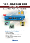
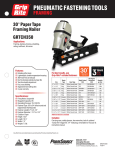
Operating Manual and Parts List
MODEL GR100
Because quality work demands quality tools
WARNING
READ THESE INSTRUCTIONS CAREFULLY BEFORE OPERATING
COMPRESSOR. IMPROPER USE CAN RESULT IN SERIOUS INJURY.
Distributed By
TABLE OF CONTENTS
Table of Contents
1
Safety Instructions
2
Warning Labels
3
Specifications
4
Set Up
5
Compressor Description
6
Compressor Parts Description
7
Operation
8
Maintenance
10
Compressor Schematics
11
Compressor Parts List
12
Troubleshooting
13
Storage
13
Warranty
14
WARNING
This manual contains important safety and operating instructions that must be followed.
You must read and understand this manual b efore operating this compressor. Failure
to follow all instructions can result in serious injury to operator and bystanders, or
damage to compressor and attachments.
1
SAFETY INSTRUCTIONS
WEAR ANSI Z87.1 APPROVED EYE PROTECTION - Always wear approved eye protection equipment that
provides both front and side eye protection when operating the compressor.
DO NOT EXCEED MAXIMUM RECOMMENDED OPERATING PRESSURE OF AIR-POWERED TOOLS OR
OTHER EQUIPMENT BEING USED- Spray guns and other low to medium pressure equipment can burst,
causing serious injury to user and bystanders. Read and follow all manufacturers' pressure recommendations
before connecting tools, sprayers, or other equipment to compressor. Use extreme care when using the
compressor with tires, inner tubes, and other inflatables, as excessive pressure or rapid inflation can cause these
items to burst.
CONNECT COMPRESSOR POWER CORD ONLY TO A PROPERLY GROUNDED POWER OUTLET USING
AN APPROVED 3-PRONG GROUNDED EXTENSION CORD- Using an improperly grounded outlet or extension
cord can result in shock or electrocution. Electrical wiring, outlets, extension cords, and current protection
devices such as fuses and circuit breakers must meet local electrical and safety codes, as well the requirements
of the National Electrical Code. A ground -fault circuit interrupter (GFCI) device may be required for compressor
use outdoors, in garages, and in damp locations.
USE EXTENSION CORD THAT IS PROPERLY SIZED - Using an undersize cord can result in overheating of
cord and short-circuiting, resulting in fire and damage to property. Use a UL -listed extension cord rated to safely
handle the power requirements of the compressor.
DO NOT OPERATE IF FLAMMABLE VAPORS ARE PRESENT - The electric motor and pressure switch may
produce sparks, which can ignite flammable vapors and cause fire or explosion. Flammable vapors from
gasoline, solvents, adhesives, and other chemicals may drift some distance from the source, or build up in low
areas. Operate the compressor only in well-ventilated areas that are free of flammable vapors.
DO NOT OPERATE IN THE RAIN OR IN WET AREAS - Operating an electric compressor in wet conditions can
result in severe shock or electrocution. Operate only in dry conditions, using a properly grounded power outlet
that conforms to local and national electrical code requirements. An outlet with ground -fault circuit interrupter
(GFCI) protection is recommended for use outdoors or in garages, and may be required by local electrical codes.
DO NOT TOUCH COMPRESSOR HEAD OR TUBING WHEN UNIT IS OPERATING - Normal compressor
operation will cause tubing and other components to become extremely hot. Contact with hot parts can cause
serious burns. Allow unit to cool before handling.
2
SAFETY INSTRUCTIONS
DO NOT DIRECT COMPRESSED AIR AT ANY BODY PARTS - Compressed air can force dirt and debris into
eyes or skin, causing serious injury. Never place hands or body parts over a pressurized nozzle or fitting. Use
care when connecting and disconnecting air hose to at tachments, pneumatic tools, and other air -powered
devices.
KEEP FLAMMABLE SPRAYS AWAY FROM SPARKS AND OTHER SOURCES OF IGNITION - Spraying
flammable liquids such as oil -base paints, sealers, and finishes near sparks, open flame, and other sources of
ignition such as pilot lights, appliances, water heaters, furnaces, etc. can result in explosion and fire. Turn off all
pilot lights, and avoid using electrical appliances, heaters, torches, and other equipment that may produce sparks
or flame. Keep compresso r as far away from spraying area as possible by using an air hose of sufficient length
to prevent spray mist from being ignited by electrical sparks from compressor operation.
DO NOT TAMPER WITH COMPRESSOR PRESSURE SWITCH SETTINGS - The pressure switch settings set at
the factory provide the maximum safe operating pressure recommended for this compressor. Altering these
settings can result in over-pressurization, risk of tank, hose, and pneumatic equipment failure, and serious injury
to operator and bystanders.
USE AIR HOSE RATED FOR 150 PSI OR GREATER - Air hose must be rated to safely handle maximum
compressor pressure. Air hose that does not meet minimum pressure requirements can rupture, releasing high
pressure air. Replace a cracked or leaking air hose immediately to prevent serious injury from contact with high
pressure air streams.
WARNING LABELS
Your unit includes several important Warning Labels that must be legible at all times.
Drain Tank Label
Main Warning Label
3
Not A Step Label
SPECIFICATIONS
DESCRIPTION
SPECIFICATION
MODEL
GR100
Horsepower
1 (Peak)
Tanks
1
Air Storage Capacity
1 Gallons
Maximum Air Pressure
150 PSI
Weight
23 Lbs.
Size ( L X W X H)
14.6” X 14.2” X 13.4”
CFM
1 @ 40 PSi
0.6 @ 90 PSI''
Pressure Switch - ON
105 PSI
Pressure Switch - OFF
135 PSI
Power Requirements
115 V 60 Hz. 5 Amps
Compressor Type
Oil-less, Piston
4
SET UP
Your new compressor is fully assembled and will be ready for use after a brief "break
-in"
procedure that will help your unit deliver years of trouble
- free service. This procedure should
be followed before placing the unit in service for the first time, after replacing the check valve,
or when the piston or cylinder has been replaced.
CAUTION: Failure to follow all break-in instructions may result in serious damage to your
compressor.
Power Connection
Grounding
This compressor is equipped with a 3-prong grounding plug that must be connected to a
properly grounded outlet, or heavy
- duty extension cord of sufficient size to handle compressor
current. A ground fault circuit interrupter may be required- check local codes for
requirements.
Break-in Procedure
1. Set the On/Auto-Off lever to the "OFF" position.
2. Plug the power cord into the power receptacle.
3. Open the tank drain valve completely.
4. Move the pressure switch lever to "ON/AUTO" position. The compressor will start.
5. Allow the compressor to run continuously for 15 minutes. Make sure the drain valve
remains open, and there is no pressure build-up inside the tank.
6. After 15 minutes, close the drain valve by turning the drain knob. The tank will
pressurize, and the motor will stop automatically when full pressure is reached. The
compressor is now ready for use.
5
COMPRESSOR DESCRIPTION
16
15
10
1
2
11
3
9
4, 13
5
14
6
12
8
7
GR-100
6
COMPRESSOR PARTS DESCRIPTION
KEY
DESCRIPTION
FUNCTION
1
Tank Pressure Gage
Indicates air pressure in air tank(s)
2
Air Outlet Pressure Gage
Indicates air pressure to air hose
3
Air Outlet Fitting
Allows quick connection of air hose
4
Regulator Control Knob
Adjusts hose pressure setting
5
Air Storage Tank
Stores air
6
Rubber Foot
Provides stable footing, reduces vibration
7
Compressor Frame
Supports compressor components
8
Air Tank Drain Fitting
Allows air and moisture to be drained
9
115v Ac Power Cord
Provides power to compressor motor
10
Pressure Switch
Controls compressor motor start/stop
11
Switch On-Off Lever
Turns compressor on or off
12
Safety Relief Valve
Releases excessive air pressure
13
Air Pressure Regulator
Controls air pressure
14
Cooling System
Cools compressor components
15
Circuit Breaker
Protects wiring from overloads
16
Handle
Use to lift and carry unit
7
OPERATION
Start Unit
1. Make sure On-Auto/Off switch lever (11) is
set to "Off" and drain valve (8) on bottom
of tank is closed securely.
11
2. Attach air hose to compressor
quick-connect coupling (3).
3
3. Attach air-powered accessory to air hose.
Use female quick-disconnect coupling on
4
end of air hose.
8
4. Turn On-Auto/Off switch lever to "Auto",
and allow compressor to pressurize tank.
5. Pressure switch will stop motor when tank
pressure reaches pressure switch high
pressure setting.
6. Adjust discharge air pressure setting by
turning air pressure adjustment knob (4).
Discharge pressure gage (2) indicates air
pressure.
7. As air is used, tank pressure will gradually
decrease until minimum tank pressure
switch setting is reached. Pressure
11
switch will start compressor motor, and
pressurize air tanks until maximum air
pressure setting is reached. Unit will
continue to cycle automatically as long as
On-Auto Off switch lever is set to "Auto."
8
OPERATION
8.
When done, turn On
-Auto/Off switch lever to Off, and unplug power cord from power
receptacle.
NOTE: Do not unplug power cord while compressor is running. Always use
On-Auto/Off switch to shut compressor off.
9.
10.
Disconnect air tool or accessory, and disconnect air hose from quick connect coupling.
Open tank drain valve slightly, and allow tank pressure to drain. Open drain valve
completely after air pressure has been allowed to escape, and allow all moisture to
drain from tanks. Tip tanks if necessary to allow tanks to drain completely.
11.
Close tank drain valve, and tighten valve securely to prevent air leakage when
compressor is started.
12.
Place compressor in a clean, dry location, protected from the rain or other sources of
excessive moisture.
9
MAINTENANCE
Lubrication
Your GripRite Compressor is oil-less and contains sealed bearings that are lubricated for the
life of the compressor. No additional lubrication is required.
Maintenance Schedule
Daily
Drain moisture from tanks daily. Open drain slowly and let air pressure bleed
down gradually before opening drain valve completely. Use care when
tipping compressor to drain tanks.
Weekly
Clean exterior of compressor. Keep air intake vents clear.
Monthly
Check safety relief valve operation. (Pull safety relief valve ring - valve must
open and release air pressure in tank. Release valve ring- valve must seal
tightly.)
Check warning labels for legibility, and replace if necessary. Contact your
Grip-Rite dealer for replacement labels.
Check air filter element (Key 9, Parts Schematic) and clean or replace as
required.
Check compressor power c ord and plug for damage. Don't use compressor if
cord is damaged. Contact your Grip-Rite dealer for service.
6 Months
Check gages for correct readings.
Check fittings and connections for leaks and tighten as required.
Yearly
Check tanks for cracks, corrosion, leaks, or other damage. Never use a
compressor with a damaged tank.
10
COMPRESSOR SCHEMATICS
GR-100
11
COMPRESSOR PARTS LISTS
GR-100
GR-100
1
Cylinder Head
PACP449
27
Unloading Tube
PACP469
2
Allen Bolt Set
PACP450
28
Pressure Switch
PACP470
3
Exhaust Elbow
PACP48
29
Strain Relief Bushing
PACP384
4
Exhaust Valve Seat
PACP451
30
Unloading Tube
PACP233
5
Cylinder
PACP452
31
Regulator
PACP388
6
Rod Set
PACP453
32
Quick Coupler
PACP448
7
Motor Set
PACP454
33
Pressure Gauge
PACP390
8
Front Cover
PACP455
9
Air Filter Set
PACP456
10
Running Capacitor
PACP457
11
Shroud
PACP458
12
Hexagon Bolt Set
PACP459
13
Power Cable
PACP386
14
Cable
PACP460
15
Gasking
PACP112
16
Circuit Breaker
PACP461
17
Air Tank
PACP462
18
Drain Valve
PACP35
19
Rubber Pad
PACP463
20
Grip
PACP464
21
Pressure Relief Valve
PACP465
22
Plug
PACP56
23
Exhaust Elbow
PACP466
24
Check Valve
PACP467
25
Unloading 3-Way Pipe
PACP334
26
Unloading Tube
PACP468
12
TROUBLESHOOTING
PROBLEM
Compressor won't start
CAUSE
REMEDY
Circuit breaker tripped
Reset breaker
Power turned off.
Turn power on
Defective cord or plug
Replace
Drain plug open
Close drain plug
Safety relief valve stuck open
Replace
Air fitting on hose stuck open
Repair or replace
Safety relief valve pops open
Pressure switch misadjusted
Adjust pressure switch
Tool, sprayer, or other accessory
doesn't work properly.
Air pressure too low or too high
Adjust regulator
Unit runs continuously
Air usage greater than compressor
capacity
Check CFM requirements of air
tool or accessory being used
Compressor doesn't shut off
STORAGE
§ Open tank drain valve and allo
w all air pressure to escape.
§ Drain all moisture out of tanks, and close drain valves.
§ Disconnect air hose and wind hose carefully for storage
§ Inspect compressor for wear, damage, or missing parts, and repair as needed.
§ Store unit in a dry, cool place.
§ Storage in vehicles or trailers- secure the compressor to keep it from tipping or being
damaged by contact with other equipment. Make sure gages and knobs are clear of
other objects that could cause damage.
§ Do not stack or place heavy objects on top of compressor.
13
PNEUMATIC TOOL/COMPRESSOR WARRANTY
Pneumatic nailers, staplers & compressors marketed under the GRIP RITE brand are warranted to be
free from defects in workmanship & materials (except rubber o-rings, bumpers, seals, driver blades, dipsticks,
& air filters) for a period of one year from the date of original purchase.
TM
This warranty will not apply when:
?
The original receipt (or copy of the original receipt), showing the original purchase date, is not
provided with tools/compressors sent in for warranty repair
?
The tool/compressor has been misused, abused or improperly maintained
?
Alterations have been made to the original tool/compressor
?
Repairs have been attempted/made to the original tool/compressor by any entity other than a
proprietary PRIMESOURCE® service/warranty center or authorized service/warranty center
?
Non- GRIP-RITE TOOLS / GRIP-RITE COMPRESSORS parts have been used
?
The tool has suffered any physical damage due to the use of non-PRIMESOURCE® approved
fasteners*
?
Repairs are required due to normal wear & tear
?
The tool/compressor has been inadequately packaged leading to damage in-transit to the
service/warranty center
TM
TM /
*Approved fasteners include the following brands GRIP-RITE FAS'NERS ,FAS'NERS UNLIMITED
TM
TM
IN NO EVENT SHALL PRIMESOURCE® BE LIABLE FOR ANY INDIRECT, ACCIDENTAL OR
CONSEQUENTAL DAMAGE FROM THE SALE OR USE OF THESE PRODUCTS. THIS DISCLAIMER APPLIES
BOTH DURING & AFTER THE TERM OF WARRANTY.
THIS IS OUR WARRANTY & IS EXPRESSLY IN LIEU OF ALL OTHER WARRANTIES, EXPRESS OR IMPLIED,
INCLUDING THE WARRANTIES OF MERCHANTABILTY AND FITNESS FOR A PARTICULAR
PURPOSE (EXCEPT AS MAY BE OTHERWISE PROVIDED BY LAW).
This limited warranty gives you specific legal rights, and you may also have other rights, which vary, from
state to state.
PNEUMATIC TOOL/COMPRESSOR SERVICE INFORMATION
Should any mechanical problems develop during the life of your equipment the following options are
available for service and parts:
?
Call (800)676-7777 where you will be routed to the nearest PRIMESOURCE® distribution center
and directed to the nearest authorized service/warranty center
?
Log on to our website at www.primesourcebp.com where you will find a list of our authorized
service centers
?
Contact the PRIMESOURCE® Factory Warranty Center directly at Phone: (800)207-9259 or
Fax: (800)207-9614
STEPS TO TAKE WHEN SHIPPING TOOLS
?
Adequately package the product to avoid damage in-transit (in the case of pneumatic tools, the original
blow mold plastic carrying case is considered adequate packaging)
?
Provide the original/copy of receipt showing the original purchase date
?
Insure your shipment with the shipping company. PRIMESOURCE® will not be responsible for any
tool/compressor that is lost or damaged by the shipper on route to the PRIMESOURCE®
service/warranty center