1
SETUP & OPERATION MANUAL
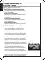
4 inch x 36 inch Belt /
6 inch Disc Sander
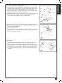
Features
●● 0 to 45º tilting work table can
be angled for miter polishing
●● Belt sander tilts to work both
horizontally and vertically,
grinding and polishing flat and
cambered surfaces
●● Strong cast iron base, steel
belt bed & aluminum disc
●● 6 in. diameter aluminum disc
backing plate
●● Quick-release system ensures
easy belt change
●● Belt is easily adjusted with
tracking knob
●● Provided with an L-shaped
steel work stop
●● Safety on/off switch with
removable key
●● Durable aluminum disc work
table with miter gauge
Specifications
●● 120 V ~ 60 Hz 4 Amp 375 W
motor
●● Includes: miter gauge,
6 in. (152 mm) peel-&-stick
sanding disc and 4 x 36 in.
(102 x 914 mm) sanding belt
●● Disc work table dim:
6-1/4 x 8-7/8 in.
(159 x 225 mm)
●● No-load motor speed:
3450 rpm
●● 16-1/2 x 4-7/8 x 2-3/8 in.
belt tablel
●● Dust port:
2-1/4 in. (58.15 mm)
●● ETL certification
●● Net weight:
3150598
37 lb. (17 kg)
Model # BD7004
General International Power Products, LLC
6243 Industrial Parkway
Whitehouse, OH 43571 USA
General International Power Products Ltd.
117-6741 Cariboo Rd.
Burnaby, BC V3N 4A3 Canada
website: www.gipowerproducts.com
BD7004 man v.150311
English
THANK YOU
for choosing this General International machine. This tool has been
carefully tested and inspected before shipment and if properly used and
maintained, will provide you with years of reliable service. To ensure
optimum performance and trouble-free operation, and to get the most
from your investment, please take the time to read this manual before
assembling, installing and operating the unit.
The manual’s purpose is to familiarize you with the safe operation, basic
function, and features of this tool as well as the set-up, maintenance and
identification of its parts and components. This manual is not intended
as a substitute for formal woodworking instruction, nor to offer the user
instruction in the craft of woodworking. If you are not sure about the safety
of performing a certain operation or procedure, do not proceed until you
can confirm, from knowledgeable and qualified sources, that it is safe to do so.
Once you’ve read through these instructions, keep this manual handy for
future reference.
®
GENERAL INTERNATIONAL
WARRANTY
All component parts of General® International products are carefully
inspected during all stages of production and each unit is thoroughly
inspected upon completion of assembly.
2-Year Limited Warranty
All products are warranted for a period of 2 years (24 months) from the
date of purchase. General® International agrees to repair or replace any
part or component which upon examination, proves to be defective in
either workmanship or material to the original purchaser during this 2-year
warranty period, subject to the “conditions and exceptions” as listed below.
Repairs made without the written consent of General International will void
the warranty.
Disclaimer
The information and specifications in this manual pertain to the unit as
it was supplied from the factory at the time of printing. Because we are
committed to making constant improvements, General International
reserves the right to make changes to components, parts or features of
this unit as deemed necessary, without prior notice and without obligation
to install any such changes on previously delivered units. Reasonable care
is taken at the factory to ensure that the specifications and information in
this manual corresponds with that of the unit with which it was supplied.
However, special orders and “after factory” modifications may render some
or all information in this manual inapplicable to your machine. Further, as
several generations of this tool model and several versions of this manual
may be in circulation, if you own an earlier or later version of this unit, this
manual may not depict your machine exactly. If you have any doubts or
questions contact your retailer or our support line with the model and serial
number of your unit for clarification.
To file a Claim
To file a claim under our Standard 2-year Limited Warranty, all defective
parts, components or machinery must be returned freight or postage
prepaid to General® International, or to a nearby distributor, repair center
or other location designated by General® International. For further details
contact our service department: USA toll-free (844) 877-5234 or (419)
877-5234 / Canada toll-free (888) 949-1161 or (604) 420-2299 or through
our website: www.gipowerproducts.com.
Along with the return of the product being claimed for warranty, a copy of
the original proof of purchase and a “letter of claim” must be included (a
warranty claim form can also be used and can be obtained, upon request,
from General® International or an authorized distributor) clearly stating
the model and serial number of the unit (if applicable) and including
an explanation of the complaint or presumed defect in material or
workmanship.
CONDITIONS AND EXCEPTIONS
This coverage is extended to the original purchaser only. Prior warranty
registration is not required but documented proof of purchase, i.e. a copy
of original sales invoice or receipt showing the date and location of the
purchase as well as the purchase price paid, must be provided at the time
of claim.
2
English
Warranty does not include failures, breakage or defects deemed after
inspection by General® International to have been directly or indirectly
caused by or resulting from; improper use, or lack of or improper
maintenance, misuse or abuse, negligence, accidents, damage in
handling or transport, or normal wear and tear of any generally considered
consumable parts or components.
Repairs made without the written consent of General® International will
void all warranty.
READ ALL INSTRUCTIONS
BEFORE OPERATING
SAVE THESE INSTRUCTIONS
Before attempting to operate your new tool, please read these instructions
thoroughly. You will need these instructions for the safety warnings,
precautions, assembly, operation, maintenance procedures, parts list and
diagrams. Keep your invoice with these instructions. Write the invoice
number on the inside of front cover. Keep the instructions and invoice in a
safe, dry place for future reference.
The warnings, cautions and instructions discussed
in this instruction manual cannot cover all possible conditions or
situations that could occur. It must be understood by the operator that
common sense and caution are factors which cannot be built into this
product, but must be supplied by the operator.
IMPORTANT SAFETY
INSTRUCTIONS
The purpose of safety symbols is to attract your attention to possible
hazards. The safety symbols, and the explanations with them, deserve
your careful attention and understanding. The safety warnings do not, by
themselves, eliminate any danger. The instructions or warnings they give
are not substitutes for proper accident prevention measures.
DANGER! Indicates an imminently hazardous situation which, if not
avoided, will result in serious injury or death.
WARNING! Indicates an imminently hazardous situation which, if not
avoided, could result in serious injury or death.
CAUTION: Indicates an imminently risky situation which, if not avoided,
could result in minor injuries or slight injury. It may also be used to notify
the user to remain alert regarding unsafe practises which may cause
property damage.
150311
3
English
WARNINGs and cautions
Be sure to read, understand and follow all safety warnings and instructions
in the supplied operator’s manual.
Work Area
1.KEEP CHILDREN AND BYSTANDERS AWAY.
All children should be kept away from the work area. Don’t let them
handle machines, tools or extension cords. Visitors can be a distraction
and are difficult to protect from injury.
2.Keep working area clean
and be sure adequate lighting is available. Cluttered areas invite
injuries.
3.MAKE WORKSHOP Child-PROOF
with padlocks, master switches, or by removing starter keys.
4.AVOID DANGEROUS ENVIRONMENTS
Don’t use power tools in damp or wet locations. Keep work area
well lit. Do not expose power tools to rain. Do not use the tool in the
presence of flammable liquids or gases.
5.STORE IDLE EQUIPMENT.
Store equipment in a dry area to inhibit rust. Equipment also should be
in a high location or locked up to keep out of reach of children.
Personal Safety
1.Learn the machine’s applications and limitations,
as well as the specific potential hazards particular to this machine.
Follow available safety instructions and safety rules carefully.
2.DON’T OVERREACH.
Keep proper footing and balance at all times. Do not reach over or
across machines that are running.
3.STAY ALERT
Watch what you are doing. Use common sense. Do not operate tool
when you are tired. Do not operate while under medication or while
using alcohol or other drugs.
4.Avoid distractions
while operating this tool.
5.Wear appropriate apparel
Do not wear loose clothing, gloves, bracelets, necklaces,or jewellery
while operating the tool. Wear face, eye, ear, respiratory and body
protection devices, as indicated for the operation or environment.
6.Always wear safety glasses
Also use face or dust mask if cutting operation is dusty, and ear plugs
during extended periods of operation. Everyday eyeglasses have only
impact resistant lenses, they are NOT safety glasses.
7.WEAR BREATHING PROTECTION. Use of this tool can generate and/or disperse dust, which may cause
serious and permanent respiratory or other injury. Many types of wood
are naturally toxic, especially in dust form. Wear a clean dust mask
if the work involves creating a lot of fine or coarse dust. Always use
NIOSH/OSHA-approved respiratory protection appropriate for the dust
exposure. Direct particles away from face and body.
8.WEAR HEARING PROTECTION, especially from repeated exposure.
9.GUARD AGAINST ELECTRIC SHOCK
Prevent body contact with grounded surfaces. For example: pipes,
radiators, ranges, refrigerator enclosures. When your body is grounded
the risk of electric shock increases. When working wherever “live”
electrical wires may be encountered, try to ascertain whether there is
a danger of shock. Even so, DO NOT TOUCH ANY METAL PARTS OF
THE TOOL while using it.
10.Always disconnect tool before servicing
and when changing accessories such as belts, bits, blades, cutters.
11.Keep guards in place
and in working order. If a guard must be removed for maintenance or
cleaning, make sure it is properly attached before using the tool again.
4
WEAR YOUR
FORESIGHT IS
BETTER THAN
NO SIGHT
English
12.ensure keys and adjusting wrenches are removed
before turning power on. Left attached, these parts can fly off a
rotating part and result in personal injury.
13.Make sure that switch is in “OFF” position
before plugging in cord to reduce the risk of unintentional starts.
14.Make sure tool is properly grounded.
If tool is equipped with three-prong plug, it should be plugged into a
three-pole electrical receptacle. Never remove the third prong.
15.Never stand on tool
Serious injury could occur if the tool is tipped or if the cutting tool is
unintentionally contacted.
16.Keep hands well away from abrasive surfaces
and all moving parts. Do not clear chips and sawdust away with
hands. Use a brush.
17.Whenever possible use a dust collector
with shaving hood to minimize health hazards.
18.SECURE WORK.
Use clamps or a vise to hold the work. It’s safer than using your hands
and it frees both hands to operate the tool.
19.DISCONNNECT THE PLUG FROM POWER
before making any adjustments. Changing attachments or
accessories can be dangerous if the tool could accidentally start.
Tool Safety
1.Make sure all cutting tools
are moving at operation speed before feeding.
2.Do not feed the material too quickly.
The tool will perform better and be safer working at the rate for which it
was designed.
3.Never leave the machine with the power on.
4.Do not force the machine.
It will do the job better and be safer at a rate for which it was designed.
Don’t force a small tool or attachment to do the work of a larger
industrial tool. Don’t use a tool for a purpose for which it was not
intended.
5.MAINTAIN TOOLS WITH CARE.
Keep tools sharp and clean for better and safer performance. Follow
instructions for lubricating and safe performance. Follow instructions
for lubricating and changing accessories. Keep handles dry, clean and
free from oil and grease.
6.AVOID UNINTENTIONAL STARTING.
Be sure the switch is in the OFF position before plugging in. Do not
carry the tool with the power connected and your finger on the trigger.
7.DO NOT USE THE TOOL
if it cannot be switched on or off. Have your tool repaired before using
it.
8.CHECK FOR DAMAGED PARTS.
Before using this tool, any part that is damaged should be carefully
checked to determine that it will operate properly and perform its
intended function. Check for alignment of moving parts, binding of
moving parts, breakage of parts, mountings, and other conditions that
may affect its operation. Inspect screws and tighten any ones that
are loose. Any part that is damaged should be properly repaired or
replaced by an authorized service center unless otherwise indicated
elsewhere in the instruction manual. Have defective switches replaced
by an authorized service center. Don’t use the tool if switch does not
turn it on and off properly.
9.Use ONLY recommended accessories.
Use of accessories NOT recommended by General International may
result in a risk of injury.
150311
5
English
Service
1.INSPECT AND MAINTAIN THE TOOL REGULARLY. Have it repaired only by an authorized repair technician.
2.MAINTAIN TOOLS WITH CARE.
Keep tools sharp and clean for better and safer performance. Follow
instructions for lubricating and safe performance. Follow instructions for
lubricating and changing accessories. Keep handles dry, clean and free
from oil and grease.
3.ENSURE THAT THE VENTILATION openings
are kept clear of debris.
4.IF THE CORDSET IS DAMAGED have it repaired
only by an authorized service center.
5.SERVICE AND REPAIRS should be made by qualified repair
technicians
at an authorized repair center. Improperly repaired tools could cause
serious shock or injury.
6.REPLACEMENT PARTS.
When servicing, use only the manufacturer’s recommended identical
replacement parts and accessories.
7.THE MANUFACTURER SHALL NOT BE LIABLE
for any changes made to the tool, nor for any damage resulting from
such changes.
Safety rules specific
to this equipment
Because each shop situation is unique, no list of safety guidelines can
ever be complete. The most important safety feature in any shop is the
knowledge and good judgement of the user. Use common sense and
always keep safety considerations, as they apply to your individual shop
situation first and foremost in mind. If you have any doubts about the
safety of an operation you are about to perform: STOP! Do not perform the
operation until you have validated from qualified individuals if the operation
is safe to perform and what is the safest method to perform it.
warning! To avoid mistakes that could cause serious, permanent
injury, do not plug the sander in until the following steps have been
completed:
Assembly and alignment
Learn the use and function of the on/off switch, back stop, belt tracking
knob, belt tension lever, work table and work table tilt knob.
Review and understanding of all safety instructions and operating
procedures in this manual.
Review of the maintenance methods for this sander.
8.Read the warning label on the tool. 9.AVOID UNINTENTIONAL STARTING. B
e sure the switch is in the OFF
position before plugging in.
10.ALWAYS CHECK AND MAKE SURE TO REMOVE ANY ADJUSTING
KEYS OR WRENCHES
before turning the tool on. Left attached, these parts can fly off a
rotating part and result in personal injury.
11.DISCONNNECT THE PLUG FROM POWER BEFORE MAKING ANY
ADJUSTMENTS.
Changing attachments or accessories can be dangerous if the tool
could accidentally start.
12.DO NOT OPERATE THIS MACHINE until it is completely
assembled
and installed according to the instructions. A machine incorrectly
assembled can cause serious injury.
NOTE: If any parts are damaged or missing, do not attempt to plug in
the power cord and turn the switch on until the damaged or missing parts
are obtained and are installed correctly.
6
English
13.Place the sander so neither the operator nor the bystanders is forced to stand in line with
the abrasive belt or disc.
14.To avoid injury Due to unexpected sander movement: • Always unplug the sander before moving it.
• Put the sander on a firm, level surface where there is plenty of room
for handling and properly supporting the workpiece.
• Support the sander so it does not rock.
• Attach the sander to its work surface, Use the fasteners and method
shown
15.Never stand on the tool.
Serious injury could occur if the tool tips. Do not store anything above
or near the tool where anyone might stand on the tool to reach them.
16.OBTAIN ADVICE
from your supervisor, instructor or another qualified person if you are
not thoroughly familiar with the operation of this machine. Knowledge
is safety.
17.NEVER TURN THE MACHINE ON before
clearing the table/work area of all objects (tools, scraps of wood, etc.).
Flying debris is dangerous.
18.NEVER TURN THE MACHINE ON with the workpiece
contacting the abrasive surface.
Kickback can occur.
19.SECURE THE MACHINE to a supporting surface.
Vibration can cause the machine to slide, walk or tip over.
20.USE A DUST COLLECTION SYSTEM.
Some types of wood dust are known to cause disease or other health
problems.
21.CLEAN THE MACHINE and dust collector
thoroughly when processing different types of materials (wood, steel or
aluminum). Combining wood and metal dust can create an explosion
or fire hazard. DO NOT SAND OR POLISH MAGNESIUM. Fire will
result.
CaUtion! This machine is not designed for heavy de-burring
operations. When finishing metals, sparks or hot fragments could cause
a fire. To avoid this:
Disconnect any dust collecting hose from the sander.
Remove all traces of wood dust from inside the sander.
Remove all traces of metal dust from inside the sander before sanding
wood again.
22.PREVENT THE WORKPIECE from contacting the sanding
surface before starting the tool.
Loss of control of the workpiece is dangerous.
23.MAINTAIN A MAXIMUM CLEARANCE OF 1/16 in.
between the table or the back stop and the abrasive disc or belt. The
workpiece could be drawn into the space between the abrasive disc
or belt and the table. When checking clearance between the belt and
work support, press the belt flat against the metal beneath it.
24.Inspect your workpiece
Make sure there are no nails or foreign objects in the part of the
workpiece to be sanded.
25.Plan your work to avoid kickbacks
when the workpiece catches on on the moving abrasive and is torn
from your hands.
26.Make sure there is no debris
between the workpiece and its supports.
27.When sanding irregularly-shaped workpieces, plan
your work support
so it will not slip and be pulled from your hands.
28.Use extra caution
with large, very small or awkward workpieces.
29.Never use this tool to finish pieces too small to hold
by hand.
150311
7
English
30.Use extra supports
(tables, saw horses, blocks, etc.) for any workpiece large enough to tip
when not held down to the bench top.
31.Never use another person as a substitute for a table
extension
or as additional support for a workpiece that is longer or wider than the
basic sander table or to help feed, support or pull the workpiece.
32.When finishing on the disc, always press the
workpiece against the "down" side of the disc.
Sanding against the side coming up from under the work table could
damage the work by making it "chatter" or it could tear it from your
hands and throw it.
33.Sand only one workpiece
at a time.
34.Before starting your work watch the sander while
it runs.
• If it makes an unfamiliar noise or vibrates a lot, stop immediately.
• Make sure the sanding disc turns counter-clockwise. If not, stop
immediately.
• Turn the sander off. Unplug the sander. Do not restart until the
problem is found and rectified.
35.AVOID AWKWARD OPERATIONS AND HAND POSITIONS.
A sudden slip could cause a hand to move into the abrasive disc or
belt. Keep fingers away from where the belt goes into the dust trap.
36.SUPPORT THE WORKPIECE firmly
with a miter gauge, backstop or work table when sanding with a belt.
Hold the workpiece firmly. Loss of control of the workpiece can result in
injury.
37.AVOID KICKBACK by sanding in accordance with the
directional arrows on the machine.
Feed the workpiece against the downward rotation side of the disc or
against the forward rotation of the belt. Loss of control of the workpiece
can result in injury.
38.Do not PERFORM LAYOUT, ASSEMBLY or SET-UP WORK on
the table
or work area when the machine is running. A sudden slip could cause a
hand to move into the abrasive surface. Severe injury can result.
39.DISCONNECT THE UNIT FROM THE POWER SUPPLY,
turn the switch off and remove the safety switch key when not in use,
before servicing or adjustment and when changing the abrasive disc or
belt.
40.TURN THE MACHINE OFF,
disconnect the machine from the power source and clean the table /
work area before leaving the machine.
41.LOCK THE SWITCH IN THE “OFF” POSITION to prevent
unauthorized use.
Someone else might accidentally start the machine and cause injury to
themselves.
42.KEEP THESE INSTRUCTIONS.
Refer to them frequently and use them to instruct other users. If you
lend someone this unit, also lend them the instructions.
43.FAILURE TO FOLLOW OPERATING INSTRUCTIONS AND SAFETY
PRECAUTIONS IN THIS INSTRUCTION MANUAL CAN RESULT IN
SERIOUS INJURY.
read the manual before starting or operating this unit.
44.FOLLOW ALL Locally applicable WIRING CODES and
recommended electrical connections to prevent
shock or electrocution.
8
English
Health Notice: Some dust created by power sanding, sawing,
grinding, drilling, and other construction activities contain chemicals
known to cause cancer, birth defects or other reproductive harm. Some
examples of these chemicals are:
─Lead from lead-based paints
─Crystalline silica from bricks and cement and other masonry products
─Arsenic and chromium from chemically-treated lumber
Your risk from these exposures varies, depending on how often you do this
type of work. To reduce your exposure to these chemicals, work in a well
ventilated area, and work with approved safety equipment, such as those
dust masks that are specially designed to filter out microscopic particles.
ElectricAL
WARNINGS AND CAUTIONS
1.Before connecting the machine to the power source, verify
that the voltage of your power supply corresponds with the voltage
specified on the motor I.D. nameplate. A power source with greater
voltage than needed can result in serious injury to the user as well
as damage to the machine. If in doubt, contact a qualified electrician
before connecting to the power source.
2.Make sure your fingers
do not contact the terminals of the power cord plug when plugging in or
unplugging the saw.
3.GROUNDED TOOLS must be plugged into an outlet
that itself is properly installed and grounded.
Grounding provides a low-resistance path to carry
electricity to ground away from the operator,
should the tool malfunction electrically.
4.DO NOT ABUSE THE CORD.
Never carry your tool by the cord or pull on the cord to unplug it.
Protect the cord from potential sources of damage: heat, oil & solvents,
sharp edges, or moving parts. Replace damaged cords immediately.
5.WHEN WORKING OUTDOORS, USE AN OUTDOOR-RATED
EXTENSION CORD.
An extension cord rated for outdoor use must be marked “W-A” or “W”.
6.This tool is for indoor use only.
Do not expose electrical power tools to moisture. Rain or wet
conditions can cause water to enter the tool and lead to electric shock.
GROUNDING INSTRUCTIONS
In the event of an electrical malfunction or short circuit, grounding reduces
the risk of electric shock. The motor of this machine is wired for 120 V
single phase operation and is equipped with a 3-conductor cord and a
3-prong grounding plug to fit a grounded type receptacle B. Do not remove
the 3rd prong (grounding pin) to make it fit into an old 2-hole wall socket
or extension cord. If an adaptor plug is used C, it must be attached to the
metal screw of the receptacle.
Note: The use of an adaptor plug is illegal in some areas, including
Canada. Check your local codes. If you have any doubts or if the
supplied plug does not correspond to your electrical outlet, consult a
qualified electrician before proceeding.
150311
9
English
EXTENSION CORDS
If you find it necessary to use an extension cord with your machine, use
only 3-wire extension cords that have 3-prong grounding plug and a
matching 3-pole receptacle that accepts the tool’s plug. Repair or replace a
damaged extension cord or plug immediately.
Make sure the cord rating is suitable for the amperage listed on the motor
I.D. plate. An undersized cord will cause a drop in line voltage resulting in
loss of power and overheating. The accompanying chart shows the correct
size extension cord to be used based on cord length and motor I.D. plate
amp rating.
Total Extension Cord Length
Amp Rating
Feet
Meters
Feet
Meters
Feet
Meters
Feet
Meters
25
8
50
15
100
30
125
40
3-10 amp
18 ga.
16 ga.
14 ga.
14 ga.
10.1 - 12 amp
16 ga.
16 ga.
14 ga.
14 ga.
12.1 - 16 amp
14 ga.
12 ga.
Use only UL or CSA approved extension cords
WARNING! Do not allow familiarity with your belt / disc sander to make
your careless. Remember that a careless fraction of a second is
sufficient to inflict severe injury.
IMPORTANT: The warnings, cautions and instructions detailed in this
manual cannot cover all possible conditions and situations that occur. It
must be understood by the operator that common sense and caution are
factors that cannot be built into this product, but must be supplied by the
operator.
Assembly
WARNING! Do not attempt to assemble the belt / disc sander, plug in
the power cord or turn on the switch if any parts are damaged or missing.
Failure to heed this warning could result in serious personal injury.
You will need some tools to assemble this unit (fig.2).
Note: It is important that the combination square be accurate.
10
Not Recommended
English
Contents
Separate all parts from the packing materials and check carefully against
fig. 3 and the list below.
Note: Make certain all parts are accounted for before discarding any
packing material.
ITEM
i
LOOSE PARTS
QTY.
Belt / disc sander assembly
1
ii
Owner’s manual
1
L
Work table
1
V
iii
Peel-and-stick sandpaper disc
1
Work table support bracket
1
U
Disc guard
1
I
Back stop
1
Miter gauge (not shown)
1
iv
Small parts bag containing:
■
Knob
1
■
Flat washer, 6.5 x 17.8 x 1.6 mm
5
■
Screw, ST4.2 x 9.5
2
■
Lockwasher, ext. M6
4
■
M6 nut
3
■
Scale label
1
■
Screw, hex hd. M6 x 1.0-14
1
Warning! For your own safety, never connect the plug to the power
source outlet or insert the switch insert key until all the assembly steps
are complete and you have read and understood the entire owner's
manual.
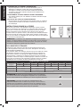
Mounting the sander to the workbench
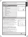
●● If the belt / disc sander is to be used in a permanent location, it should
be fastened securely to a firm supporting surface such a workbench.
●● If mounting to a workbench, holes should be drilled through the
supporting surface using the dimensions illustrated (fig.5).
1.The unit should be bolted securely using 5/16 in. screws and hex nuts
(not included). The screw length should be 1-1/2 in. (38 mm) plus the
thickness of the bench top.
2.Locate and mark the holes where the belt / disc sander is located.
3.Drill two 3/8 in. diameter holes through the workbench.
4.Place the belt / disc sander on the workbench, aligning the holes in the
base (O & R, fig.4) with the holes drilled in the workbench.
5.Insert two 5/16 in. screws and tighten hex nuts.
Attaching the sander to a mounting board
An alternate method of mounting is to fasten the belt / disc sander to a
mounting board. The board should be of sufficient size to prevent the
sander tipping while in use.
1.Use a piece of plywood at least 3/4 in. thick. Particle or chipboard can
fail under constant vibration and tipping stress on the corners.
2.Follow the instructions for mounting to a workbench, above, substituting
a board, minimum 18 in. x 24 in. (fig.5).
3.Use 5/16 in. flat head machine screws (not included), countersunk into
the bottom of the board to prevent rocking. Screw length should be
1-1/2 in. plus the thickness of the plywood board.
Caution! To prevent injury from tool movement, use 5/16 in. (8 mm)
or larger screws and nuts.
150311
11
24 in. / 24 po (61 cm) minimum
18 in. / 18 po (46 mm) minimum
English
4.Add lockwashers and hex nuts (not included) and tighten.
Sander base / Base de ponceuse
2 holes / 2 trous
diam : 3/8 in. / 3/8 po
2-21/32
in. / po
67.5 mm
3/4
in. / po
19 mm
13-7/16 in. / po
9/16
in. / po
14.3 mm
fig 5
Caution! To avoid injury from tool movement, the supporting surface
where the belt / disc sander is mounted should be watched carefully after
mounting to ensure that no movement will take place during use. If any
tipping or walking is noted, secure the workbench or the supporting
surface before operating the belt / disc sander.
Clamping the sander to the workbench
A third alternative is that the belt / disc sander can be clamped directly to
a workbench using two or more C-clamps on the base of the unit (at least
one clamp on each end- fig.6).
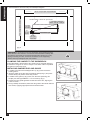
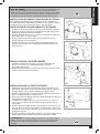
Installing sanding disc and guard
1.Locate the peel-and-stick sandpaper disc (V, fig.7) and remove the
backing from it.
2.Align the edges of the disc with the sanding plate (W, fig.7) and press
the disc firmly into position all the way around.
3.Locate the disc guard (U, fig.7) and, from the loose parts bag, two
Phillips pan head type AB M4.2 x 1.4-12 screws (a, fig.7).
4.Position the disc guard against the lower third of the disc, aligning the
holes as shown.
5.Using a Phillips screwdriver, fasten the disc guard to the sander with the
two screws, applying slight pressure to thread the holes.
12
English
Installing the back stop
1.Locate the back stop (I, fig.8) and the M6 x 1.0-14 hex head screw (b,
fig.8), lockwasher (c, fig.8) and flat washer (d, fig.8).
2.Hold the back stop in position and fasten with a wrench (e, fig.8) as
shown. Do not over tighten.
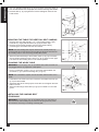
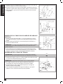
Installing the work table assembly
1.Locate the work table support bracket (f, fig.9) and, from the bag of
loose parts, three M6 x 1.0-14 hex head screws (b, fig.9), flat washers
(c, fig.9) and lockwashers (d, fig.9).
2.Position the work table support bracket against the underside of the
work table, aligning the holes as shown.
3.Fasten the work table support bracket to the work table with the screws
and washers as shown.
4.Locate the 1/4" x 11/16" x 0.6" (6.5 x 17.8 x 1.6 mm) washer (c, fig.10)
and the work table lock knob (N, fig.10) among the the bag of loose
parts.
5.Position the work table support bracket (f, fig.10) against the
corresponding holes on the left side of the base as shown. Make sure
the 9.5 mm (~3/8 in.) diameter index pin (g, fig.10) aligns with the upper
hole (h, fig.10).
6.Place the washer on the threaded shaft of the knob and insert the shaft
through the slot in the support into the threaded hole (j, fig.10) in the
base.
Warning! To avoid trapping the workpiece or your fingertips between
the table (L, fig.11) and the sanding surface (V, fig.11), the table edge
should be a maximum of 1/16 inch (1.5 mm) from the sanding surface.
7.Loosen the three hex screws (b, fig.11), that hold the work table to the
work table support bracket and adjust the table.
150311
13
English
8.Use your Operator's Manual (k, fig.12) as a spacer. Place ten pages of
this manual between the sandpaper disc and and the edge of the table.
9.Hold the table (L, fig.12) against the manual and tighten the three hex
head screws.
Mounting the table for vertical belt sanding
1.Remove back stop bolt {the M6 x 1.0 - 14 hex head screw (b, fig.8),
lockwasher (c, fig.8) and flat washer (d, fig.8)} and back stop.
2.Remove the work table assembly from the disc sander side by
unscrewing the work table lock knob and washer.
Note: The belt sanding bed may be raised to the vertical position by
loosening the hex socket head screw and then pushing the belt bed into
the vertical position. See Positioning the Belt Bed, below.
3.Attach the table assembly to the auxiliary holes (G, fig.13) in the back
side of belt bed. Make sure the index pin (g, fig.13) goes into the upper
hole when the belt sanding bed is in the vertical position.
Squaring the work table
Warning! To avoid injury from an accidental start, make sure the tool
is unplugged before any alignment is attempted.
1.Using a combination square (l, fig.14), check the angle between the
work table (L, fig.14) and the sanding disc (V, fig.14).
Note: The combination square must be accurate. Please check it if in
doubt.
2.If the table is not at 90º to the disc, loosen the work table lock knob (N,
fig.14) and tilt the table.
3.Adjust the table to be exactly square to the disc and re-tighten the work
table lock knob.
4.Attach the table angle scale label (m, fig.14) to indicate 0º on the dust
guard.
Installing the sanding belt
Tensioning
Warning! To avoid injury from an accidental start, turn the switch to
Off, remove the switch safety key and remove the plug from the power
source before removing or installing a sanding belt.
14
English
5.For ease of installation, loosen the bed-locking hex socket head screw
(J, fig.15) and raise the belt bed a little.
6.Printed on the smooth side (inside) of the sanding belt (F, fig.15), you
will find a directional arrow (q, fig.15). The sanding belt must run in the
direction of this arrow to ensure the splice does not come apart.
7.Move the tension lever (C, fig.16) to the right (-), when facing the back
side of the machine, to release the belt tension.
8.Place the sanding belt over the bed (E, fig.15), the drive drum (n, fig.15)
and the idler drum (o, fig.15) with the directional arrow pointing as
shown. Make sure the belt is centered on both drums.
9.Move the tension lever (C, fig.16) to the left (+) to apply belt tension.
10.Be sure to tighten the bed-locking hex socket head screw when the belt
bed is in the desired position.
11.Plug in the power cord.
12.Turn the switch on and immediately off. Notice if the belt tends to move
off the idler drum or the drive drum. If it shows no tendency to move to
the side, it is tracking correctly.
Tracking
1.If the sanding belt moves toward the front (sanding disc) side of the
machine, turn the belt tracking knob (D, fig.17) clockwise 1/4 turn.
2.If the sanding belt moves toward the back of the machine (away from
the sanding disc), turn the belt tracking knob counter-clockwise 1/4 turn.
3.Turn the switch on and immediately off again, noting if the belt tends
to move and in which direction it moves. Re-adjust the tracking knob if
necessary.
150311
15
English
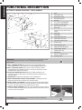
Functional Description
Getting to know your belt / disc sander
Warning! To avoid injury from accidental start, turn the switch off and
remove the plug from the power source outlet before making any
adjustments.
C.Belt tension leverMoving the lever to the right releases the
sanding belt tension; moving the lever to the left applies belt tension.
D.Belt tracking knobTurning knob counter-clockwise causes
sanding belt to track towards the disc; turning knob clockwise causes
the belt to track away from the disc.
G.Auxiliary mounting hole A
llows the table assembly to be
mounted for end-sanding when the sanding belt bed is placed in the
vertical position.
I. Back stop Supports the workpiece on the sanding belt.
J.Bed-locking hex socket head screw Loosening the screw
allows the belt bed to be raised to the vertical position.
N.Work table lock knob L
oosening the knob allows the work table
to be tilted for bevel sanding. The scale indicator is on the table support
trunnion. The bevel angle scale is attached to the base.
T.On/off safety switch Flips to the right and left to turn the machine
on and off. When the safety key (T, fig.19) is removed, the switch will not
move from the "Off" position.
Warning! After switching off, never leave the machine unattended
until it has come to a complete stop.
16
A
Base
B
Drive belt cover
C
Belt tension lever
D
Belt tracking knob
E
Belt bed
F
4 in. x 36 in. sanding belt
G
Auxiliary mounting hole
H
Back stop hex screw
I
Back stop
J
Bed-locking hex socket head
screw
K
Dust trap
L
Work table
M
Work table miter slot
N
Work table lock knob
O
Left side mounting hole
P
Power cable
Q
Dust extraction port
R
Right side mounting hole
S
On/Off safety switch
T
Safety switch key
U
Disc guard
V
Stick-on sandpaper disc
W
Sanding plate
English
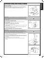
Operating Instructions
Bevel Sanding
The work table (L, fig.20) can be tilted from 0º to 45º for bevel sanding.
Loosen the work table lock knob (N, fig.20) and tilt the work table to the
desired angle as shown. Re-tighten the work table lock knob.
WARNING! To avoid trapping the work or fingertips between the table
and the sanding surface, the table should be re-positioned on the table
support to maintain a maximum of 1/16 inch betweeen the table and the
sanding surface.
Positioning the belt bed
A bed-locking hex socket screw locks the bed in either a vertical or
horizontal position.
To adjust to vertical position
1.Remove the back stop (I, fig.21).
2.Loosen the bed-locking hex socket head screw (J, fig.21) using a 6 mm
(Allen) hex key.
3.Position the belt bed (E, fig.22) vertically as shown and re-tighten the
hex socket head screw (J, fig.22).
Surface sanding on the sanding belt
Warning! To avoid injury from slips, jams or thrown pieces, adjust
the back stop to clear the sanding surface by no more than 1/16"
(1.5 mm). When checking clearance between the belt and the back stop,
press the belt flat against the metal of the belt bed beneath it.
1.Hold the workpiece (t, fig.23) firmly with both hands, keeping fingers
away from the sanding belt (F, fig.23).
2.Keep the end butted against the back stop (I, fig.23) and move the work
evenly accross the sanding belt. Use extra caution when sanding very
thin pieces.
3.For sanding long pieces, remove the back stop.
4.Apply only enough pressure to allow the sanding belt to remove
material.
150311
17
English
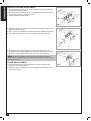
End-sanding on the sanding belt
1.It is more convenient to sand the ends of long workpieces (t, fig.24) with
the sanding belt (F, fig.24) in the vertical position.
2.See Positioning the belt bed in Operating Instructions for adjusting the
belt bed and Mounting the table for vertical belt sanding in Assembly,
above, for adjusting the work table.
3.Move the workpiece evenly across the sanding belt. For accuracy, use
the miter gauge.
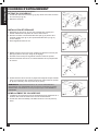
Sanding curved edges
1.Always sand inside curved edges of a workpiece (t, fig.25) on the idler
drum (o, fig.25) as shown, rather than the drive drum.
Warning! Never attempt to sand the ends of a workpiece on the idler
drum. Applying the end of the workpiece to the idler drum could cause
the workpiece to fly up and result in an injury.
2.Always sand outside curves on a workpiece (t, fig.26) on the disc sander
(V, fig.26), keeping to the left side of the sanding disc center (u, fig.26)
as shown.
Warning! Applying the workpiece to the right side of the disc could
cause the workpiece to fly up (kickback) and result in an injury.
Sanding small end-surfaces on the sanding
disc
Note: Use of the miter gauge (v, fig.27) is recommended for this
operation.
1.Always sand outside end surfaces of a workpiece (t, fig.27) on the disc
sander (V, fig.27), keeping to the left side of the sanding disc center
(u, fig.27) as shown. Always move the work across the left side of the
sanding disc as shown.
Warning! Applying the workpiece to the right side of the disc could
cause the workpiece to fly up (kickback) and result in an injury.
Warning! For your own safety, turn the switch off and remove the
plug from the power source outlet before adjusting your sander.
Note: Use a combination square (l, fig.28) to square the miter gauge
to the face of the disc. Be sure the combination square is accurate.
18
English
2.If the miter gauge (v, fig.28) is not exactly square to the sanding disc,
loosen the miter gauge knob and move the miter gauge slightly until it is
square. Then, without moving the miter gauge, tighten the knob.
3.Always position the workpiece to the left of the sanding disc center with
the disc rotating counter-clockwise as shown.
4.The table may be tilted for beveled work.
Maintenance
Warning! For your own safety, turn the switch off and remove the
plug from the power source outlet before adjusting, maintaining or
lubricating your belt / disc sander.
Warning! To avoid electrocution or fire, any repairs to electrical
systems should be done by an authorized repair center.
●● If power cord is worn, cut or damaged in any way, have it replaced
immediately.
●● Frequently blow or vacuum out any dust that may accumulate inside
the motor.
●● A coat of automobile wax applied to the work table will make it easier to
feed the work while finishing.
●● Do not apply wax to the abrasive belt bed because the belt could pick
up the wax and deposit it on the idler and drive drums, causing the belt
to slip.
Lubrication
●● The ball bearings in this machine are packed with grease at the factory.
They require no further lubrication.
sleeve bearing Lubrication
Sleeve bearings (w, fig.29) should be lubricated with 30 weight oil or
equivalent after each 10 hours of operation.
Warning! To avoid injury, turn the switch off, remove key and remove
plug from the power source outlet before oiling unit.
1.Release belt tension by moving the tension lever (C, fig.29) to the right.
2.Move the sanding belt slightly to either side of the idler drum (o, fig.29)
to expose the oval-shaped oiling hole (x, fig.29) for the idler drum sleeve
bearings.
3.Apply two or three drops of oil in the hole on each side as shown. Do
not apply more than three drops of oil. Too much oil can cause the belt
to slip and oil may get on the workpiece.
4.Adjust the belt tracking as described above in Assembly, Installing the
sanding belt, Tensioning and Tracking.
drive belt
If the drive belt is ever broken:
Cover Removal
1.Using a Phillips screwdriver (y, fig.30), remove the flat head screw
located in the middle of the cover (D, fig.30).
2.Pull off the cover.
150311
19
English
Installation and adjustment
3.Loosen the three screws (z, fig.31) to allow the pulleys to shift enough
to place the belt around them.
4.Place the new drive belt (bb, fig.31) around the motor pulley (aa, fig.31)
and the drive pulley (cc, fig.31) as shown.
5.Slightly tighten the three screws.
6.Adjust belt tension by putting a slot screwdriver blade (dd, fig.32) in the
adjusting hole (ee, fig.32).
7.Push up on the screwdriver to increase the tension between the pulleys.
8.Fully tighten the three screws, being careful not to disturb the belt.
9.Test belt tension by placing fingers on either side of the belt and
squeezing the two sides together at the mid-point between the pulleys
(ff, fig.33). There should be about 1/4" (6 mm) of give to the belt.
Note: Excessive tightness on the drive belt may cause increased
noise and also overload the motor. Excessive belt looseness may cause
it to fail prematurely.
cover replacement
10.Locate the drive belt cover and position it inside it inside the relief
edges of the drive belt housing.
11.Using a Phillips screwdriver, re-install and tighten the flat head screw.
Do not over-tighten.
20
English
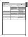
Troubleshooting
Warning! For your own safety, turn the switch off and remove the
plug from the power source outlet before troubleshooting your sander.
PROBLEM
Motor will not run
PROBABLE CAUSE
REMEDY
Defective On/Off switch
Replace defective parts before
using the belt / disc sander again
Defective power cable
Replace defective parts before
using the belt / disc sander again
Defective switch box
Replace defective parts before
using the belt / disc sander again
Burned out motor
Any attempt to repair this motor
may create a hazard unless repair
is done by a qualified service
technician
Drive belt too tight
Decrease belt tension. See
Maintenance, Drive belt, Installation
and adjustment
Applying too much pressure on the
workpiece
Ease up on sanding pressure
Excessive noise
Drive belt too tight
Decrease belt tension. See
Maintenance, Drive belt, Installation
and adjustment
Sanding belt runs off the drums
Not tracking properly
Adjust tracking. See Assembly,
Installing the sanding belt, Tension
and Tracking
Wood burns while sanding
Sanding disc or belt is glazed with
sap
Replace disc or belt
Ease up on sanding pressure
Machine slows down when sanding
150311
21
English
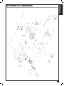
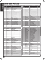
Parts List
Pos.
Part No.
Description
Qty.
Pos.
Part No.
Description
Qty.
1
B/D4603006
Knob
2
41
GB/T6170-2000
Nut M6
3
2
B/D4601015
Washer, rubber
1
42
B/D4603001D
Base
1
3
B/D4601013
Washer, notched
1
43
B/D4602009
Belt, drive
1
4
B/D4601001
Bed
1
44
GB/T819.1-2000
Screw, flat cross M5 x 10
3
5
GB/T819.1-2000
Screw, flat cross M5 x 35
1
45
GB862.2-87
Washer, countersink
2
6
GB/T70.1-2000
Bolt, hex M6 x 14
1
46
B/D4602005
Pulley, drive
1
7
GB/T862.1
Washer, spring 6
10
47
GB/T818-2000
Screw, pan hd. M6 x 25
3
8
GB/T96-85
Washer 6
9
48
GB97.1-85
Washer 6
6
9
B/D4601016
Support, work
1
49
B/D4602004
Pulley, idler
1
10
B/D4602007
Belt, sanding 4” x 36”
1
50
GB/T819.1-2000
Screw, flat hd.M5 x 25
3
11
GB/T862.1
Washer, spring 5
5
51
B/D4601011
Support, bearing
1
12
GB/T818-2000
Screw, pan M5 x 8
3
52
B/D4601012
Cover, belt
1
13
B/D4602002-2
Drum, drive
1
53
B/D4601008
Support, bed
1
14
GB/T80
Screw, socket set M8 x 10
2
54
GB/T39-1988
Nut, square M8
1
15
B/D4601009
Cap, bearing
1
55
B/D4603002
Bumper
1
16
GB/T276
Bearing w/felt washer
1
56
GB/T70.1-2000
1
17
B/D4601010
Spacer, bearing
1
Screw, hex soc.cap M8 x
25
18
B/D4604002B
Housing, switch
1
57
GB/T278-94
Bearing, ball
1
19
GB862.2-87
Washer, tooth 5
3
58
GB/T894.1
Ring, retaining 12
4
20
GB/T818-2000
Screw pan M5 x 8
5
59
B/D4602003
Shaft, drive
1
21
B/D4603011-2
Angle gauge
1
60
Nut, hex flange M5
1
22
HY7-4P
Switch
1
GB/T6177.12000
23
GB/T6170-2000
Nut, hex M8
1
61
B/D4601006
Space, guide
1
24
GB845-85
Screw, pan cross M4.2 x
16
3
62
B/D4601014
Spring, index
1
63
B/D4601003
Guide, drum
1
Cover, switch box
1
64
B/D4601002
Shaft, idler
1
Capacitor
1
65
B/D4602001
Drum, idler
1
66
B/D4601005
Lever, tension
1
67
B/D4601004
Spring, tension
1
68
B/D4601007
Spacer, lever
1
69
GB97.1-85
Washer, M5
1
70
B/D4603012
Cord clamp
1
71
GB/T818-2000
Screw, pan hd. M4 x 6
1
72
S1601012
Index
1
4603011-1
Gib block
1
25
B/D4604003A
26
27
B/D4602008
Sandpaper pad, 6”
1
28
GB/T818-2000
Screw, pan cross M6 x 12
1
29
GB/956.1
Washer, tooth 6
1
30
B/D4602006
Disc
1
31
GB845-85
Screw, pan hd. M4.2 x 9.5
5
32
B/D4603008
Guard, disc
1
33
B/D4603009A
Shroud, disc
1
34
4603003A-2
Lower cover of dust
collector
1
73
74
4603011-3
Knob
1
35
4603004B-1
Table
1
75
4603004B-3
Left table end plate
1
36
B/D4603005
Support, table
1
76
GB/T70.1-2000
Screw, hex M6 x 20
3
37
4603010
Cover, base
1
77
4603004B-2
Right table end plate
1
38
B/D4604004B
Cord w/plug
1
78
GB/T818-2000
Screw, pan hd. M5 x 10
2
39
YY7112A
Motor
1
79
4603009C
Disc cover
1
40
GB/T818-2000
Screw, pan hd. M5 x 12
3
80
4603003A-1
Upper cover of dust
collector
1
22
English
Schematic Drawing
150311
23
24
English
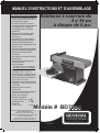
MANUEL D’INSTRUCTIONS ET D’ASSEMBLAGE
CARACTÉRISTIQUES
●● 0 à 45° d'inclinaison de la table
de travail peut être incliné pour le
polissage des onglets
●● Ponceuse à bande s’incline à
travailler à la fois horizontalement
et verticalement, meulage et
de polissage plat et surfaces
cambrées
●● Base en fonte robuste, assise
de bande en acier et disque
d'aluminium
●● Diamètre de 6 po de la plaque
d'appui du disque d’aluminium
●● Système de déclenchement
rapide permet changement facile
de la courroie.
●● Courroie est facilement ajustable
grâce à la molette d’alignement
●● Incluant une bande arrêt en
forme de L
●● Interrupteur de sécurité incluant
clé amovible
●● Table de travail du disque fait
d’aluminium avec
guide à onglets
Sableuse à courroie de
4 x 36 po
à disque de 6 po.
Spécifications
●● Moteur : 4 ampères,
375 Watts, 120 V ~ 60 Hz
●● Incluant guide à onglets 152 mm
(6 po.) disque de ponçage auto
adhérant et bande de sablage 4 x
36 po (102 x 914 mm)
●● Dimension de la table de travail
du disque : 6-1/4 x 8-7/8 po (159
x 225 mm)
●● Vitesse à vide du moteur :
3 450 tr/min
●● Table de la courroie de sablage :
16-1/2 x 4-7/8 x 2-3/8 po
(419 x 124 x 60 mm)
●● Sortie de poussière :
2-1/4 po (58.15 mm)
●● Certification ETL
●● Poids net :
3150598
37 lb (17 kg)
Modèle # BD7004
General International Power Products, LLC
6243 Industrial Parkway
Whitehouse, OH 43571 USA
General International Power Products Ltd.
117-6741 Cariboo Road
Burnaby, BC V3N 4A3 Canada
site Web : www.gipowerproducts.com
BD7004 man v.150311
Français
NOUS VOUS REMERCIONS
d’avoir choisi une machine de General International. Cette outil a été
soigneusement testée et inspectée avant de vous être expédiée, et
moyennant une utilisation et un entretien adéquats, elle vous procurera
un service fiable pendant de nombreuses années. Afin d’obtenir un
rendement optimal et une utilisation sans problème, et d’optimiser
votre investissement, veuillez prendre le temps de lire ce manuel avant
d’assembler, d’installer et d’utiliser l’unité.
Ce manuel vise à vous familiariser avec l’utilisation sécuritaire, les
fonctions élémentaires et les caractéristiques de cette scie ainsi qu’avec
le réglage, l’entretien et l’identification de ses parties et composantes. Il
n’est pas conçu pour remplacer un enseignement théorique sur le travail
ni pour offrir à l’utilisateur une formation en la matière. En cas de doute
concernant la sécurité d’une opération ou d’une procédure, demandez
l’aide d’une personne qualifiée avant d’entamer le travail.
Une fois que vous avez lu ces instructions, conservez ce manuel aux fins
de consultation ultérieure.
GARANTIE DE
GENERAL® INTERNATIONAL
Toutes les composantes des machines de General® International sont
soigneusement inspectées durant chacune des étapes de production, et
chaque unité est inspectée en profondeur une fois l’assemblage terminé.
Garantie Standard
Limitée de 2 ans
En raison de son engagement envers la qualité et la satisfaction du
consommateur, General® International accepte de réparer ou de remplacer
toute pièce qui, suite à l’examen, se révèle défectueuse quant aumatériel
et au fini d’exécution pour une période de 2 ans (24 mois) suivant la date
d’achat. Pour se prévaloir de la garantie, l’acheteur doit retourner toutes
les pièces défectueuses port payé à General® International.
Les réparations effectuées sans le consentement écrit de General®
International annuleront la garantie.
Clause de non-responsabilité
L’information et les caractéristiques présentées dans ce manuel se
rapportent à la machine telle qu’elle est sortie de l’usine au moment de
mettre sous presse. En raison de son souci d’amélioration constante,
General International se réserve le droit de modifier des composantes, des
pièces ou des caractéristiques de la machine si cela est jugé nécessaire,
sans préavis et sans obligation d’effectuer ces modifications sur les
machines déjà vendues. On prend soin de s’assurer à l’usine que les
caractéristiques et l’information présentées dans ce manuel correspondent
à la machine avec laquelle il est fourni.
Toutefois, en raison de commandes spéciales et de modifications
réalisées “hors de l’usine,” une partie ou la totalité de l’information
contenue dans ce manuel peut ne pas s’appliquer à votre machine. De
plus, comme il se peut que plusieurs générations de ce modèle d'outil et
plusieurs versions de ce manuel soient en circulation, il est possible que
ce manuel ne décrive pas exactement votre machine si vous possédez
une version antérieure ou ultérieure. Si vous avez des doutes ou des
questions, veuillez communiquer avec votre détaillant ou notre ligne de
soutien technique et mentionner le numéro de modèle et de série de votre
machine afin d’obtenir des éclaircissements.
Demande de Réclamation
Pour présenter une demande de réclamation en vertu de notre Garantie
Standard Limitée de 2 ans, ou en vertu de notre Garantie Limitée à Vie,
toute pièce, composante ou machinerie défectueuse doit être retournée,
port payé, à General® International, ou encore à un distributeur, un centre
de réparation ou tout autre emplacement situé près de chez vous et
désigné par General® International. Pour plus d’informations ou si vous
avez besoin d’aide pour remplir une demande de réclamation, contactez
notre département de service. USA : numéro sans frais (844) 877-5234
ou (419) 877-5234 / Canada : numéro sans frais (888) 949-1161 ou
(604) 420-2299 ou sur notre site Web : www.gipowerproducts.com.
Une copie de la preuve d’achat originale ainsi qu’une lettre (un formulaire
26
FRançais
de réclamation de garantie peut vous être fourni sur demande par
General® International ou par un distributeur agréé) spécifiant clairement le
modèle et le numéro de série de l’unité (si applicable), et faisant état de la
plainte ou du défaut présumé, doivent être jointes au produit retourné.
CONDITIONS ET EXCEPTIONS
Cette couverture ne s’applique qu’au premier acheteur. Un enregistrement
préalable de la arantie n’est pas requis. Par contre, une preuve d’achat –
soit une copie du coupon de caisse ou du reçu original, sur lequel figurent
la date et le lieu d’achat ainsi que le prix payé – doit être fournie lors de la
réclamation.
La Garantie ne couvre pas les défaillances, bris ou défauts qui, après
examen par General® International, sont considérés comme étant
directement ou indirectement causés par ou résultant de: une utilisation
incorrecte, un entretien inadéquat ou l’absence d’entretien, un usage
inapproprié ou abusif, la négligence, un accident, des dommages survenus
durant la manutention ou le transport, ou encore l’usure normale ou la
détérioration des pièces et composantes considérées, de façon générale,
comme étant des consommables.
Les réparations effectuées sans le consentement écrit de General®
International annuleront toute garantie.
LISEZ TOUTES LES INSTRUCTIONS
AVANT L’UTILISATION
CONSERVEZ CES INSTRUCTIONS
Avant d’essayer de faire fonctionner votre nouvel outil, veuillez lire
les instructions au complet. Vous aurez besoin de ces instructions
pour les avertissements de sécurité, les précautions, l’assemblage, le
fonctionnement, les procédures d’entretien, la liste des pièces et les
schémas des pièces. Gardez votre facture avec ces instructions. Écrivez
votre numéro de facture à l’intérieur de la page couverture. Gardez les
instructions ainsi que la facture dans un endroit sûr et sec pour référence
future.
Les avertissements, les précautions et les
instructions discutés dans ce manuel ne peuvent pas couvrir toutes les
conditions et les situations qui pourraient survenir. L’utilisateur se doit de
comprendre que le bon sens ainsi que la prudence sont des facteurs qui
ne peuvent être incorporés dans ce produit, mais peuvent être fournis
par l’utilisateur lui-même.
RegLES DE SÉCURITÉ ET
DIRECTIVES
L’objectif des symboles de sécurité est d’attirer votre attention sur les
risques potentiels. Les symboles de sécurité, ainsi que les explications les
accompagnant, nécessitent votre attention et votre compréhension. Les
avertissements de sécurité n’éliminent pas d’eux-mêmes tous les dangers.
Les instructions ou les avertissements qu’ils donnent ne sont pas un
remplacement aux mesures de prévention d’accident appropriées.
DANGER! Indique une situation à risque imminent, laquelle si elle n’est pas
évitée, causera de sérieuses blessures ou la mort.
AVERTISSEMENT! Indique une situation à risque imminent, laquelle si
elle n’est pas évitée, pourrait causer de sérieuses blessures ou la mort.
Attention: Indique une situation à risque imminent, laquelle si elle
n’est pas évitée, peut causer des blessures mineures ou des blessures
légères. Il peut aussi être utile de demeurer alerte au sujet des pratiques
non sécuritaires qui pourraient causer des dommages à la propriété.
150311
27
Français
AVERTISSEMENTS ET
PRÉCAUTIONS
Assurez-vous de lire, comprendre et suivre tous les avertissements et
consignes de sécurité dans le manuel de l'opérateur.
ZONE DE TRAVAIL
1.TENEZ LES ENFANTS ET AUTRES PERSONNES ÉLOIGNÉS
Tous les enfants doivent être tenus à l'écart de la zone de travail.
Ne les laissez pas utiliser des machines, des outils ou des rallonges
électrique. Les visiteurs peuvent être une distraction et sont difficiles à
protéger contre les blessures.
2.GARDER LE LIEU DE TRAVAIL PROPRE
et assurez-vous d'un éclairage adéquat est disponible. Les endroits
encombrés peuvent crée des blessures.
3.METTRE L'ATELIER L’ÉPREUVE DES ENFANTS
avec des cadenas, avec les interrupteurs principaux ou en retirant les
clés de démarrage.
4.ÉVITEZ LES ENVIRONNEMENTS DANGEREUX
Ne pas utiliser d'outils électriques dans des endroits humides ou
mouillés. Garder la zone de travail bien éclairé. Ne pas exposer les
outils électriques à la pluie. Ne pas utiliser l'outil en présence de
liquides ou gaz inflammables.
5.ENTREPOSAGE DES ÉQUIPEMENTS
Entreposer vos équipements dans un endroit sec pour empêcher la
rouille. Les équipements devraient aussi être entreposés dans un
endroit verrouillé ou garder hors de portée des enfants.
SÉCURITÉ PERSONNELLE
1.APPRENDRE LES APPLICATIONS ET LES LIMITES DE LA
MACHINE
ainsi que les risques spécifiques à cette machine. Suivez les
instructions de sécurité disponibles et les règles de sécurité
attentivement.
2.NE PAS TROP SE PENCHER
Garder une position correcte en tout temps.
3.DEMEURER ALERTE
Regardez ce que vous faites. Utilisez votre bon sens. Ne pas utiliser
l'outil lorsque vous êtes fatigué. Ne pas l'utiliser sous médication ou si
vous avez consommer de l'alcool ou d'autres drogues.
4.ÉVITEZ LES DISTRACTIONS DURANT LES SESSIONS DE travail.
5.PORTEZ DES VÈTEMENTS APPROPRIÉS.
Ne portez pas de vêtements amples, gants, bracelets, colliers, bijoux
lors de l'utilisation de l'outil. Porter un masque ou un dispositif de
protection pour les yeux, les oreilles, les voies respiratoires et pour le
corps comme indiqué dans le fonctionnement de l’appareil.
6.PORTEZ TOUJOURS DES LUNETTES DE SÉCURITÉ.
Utilisez également un masque anti- poussière si le sablage soulève de
la poussière, et des bouchons d'oreille pendant de longues périodes
de fonctionnement. Les lunettes ordinaires ont des verres résistant aux
chocs, ils NE SONT PAS des lunettes de sécurité.
7.PORTEZ UNE PROTECTION RESPIRATOIRE.
L'utilisation de cet outil peut produire et / ou répandre de la poussière,
ce qui peut entraîner des problèmes respiratoires graves et
permanents ou d'autres blessures. De nombreux types de bois sont
naturellement toxiques, surtout sous forme de poussière. Porter un
masque anti-poussière propre si le travail consiste à créer beaucoup
de poussière fine ou grossière. toujours utiliser NIOSH / OSHA
approuvé une protection respiratoire appropriée pour l’exposition à la
poussière. Diriger les particules loin du visage et du corps.
8.PORTEZ UNE PROTECTION AUDITIVE,
Spécialement si exposé à répétition.
9.ATTENTION AUX DÉCHARGES ÉLECTRIQUES
Éviter tout contact corporel avec des surfaces en mises à la terre. Par
exemple: tuyaux, radiateurs, cuisinières, réfrigérateurs. Quand votre
28
PORTEZ VOS
PRÉVOYANCE EST
MIEUX QUE DE
NE PAS VOIR
FRançais
corps est en mis à la terre le risque de choc électrique augmente.
Lorsque l'on travaille, il est possible d’avoir certains fils électriques
avec courant autour de vous, tenter de déterminer si il y a un danger
de choc. Ne touchez pas les parties métalliques DE L'OUTIL tout en
l'utilisant.
10.TOUJOURS DÉBRANCHER L’OUTIL AVANT DE FAIRE
L’ENTRETIEN
et changer les accessoires tels que bandes abrasives, les courroies,
des lames ou couteaux.
11.LAISSEZ LES GARDES EN PLACE
et en ordre de marche. Si un garde doit être enlevé pour l'entretien ou
le nettoyage, assurez-vous qu'il est correctement fixé avant d'utiliser à
nouveau l'outil.
12.VERIFIER QUE LES CLÉS ET MOLETTES DE RÉGLAGE SONT
RETIRÉES
avant la mise sous tension, laisser en place ces pièces peuvent
s'envoler au démarrage et entraîner des blessures.
13.ASSUREZ-VOUS QUE LE COMMUTATEUR EST EN POSITION
ARRET «OFF»
avant de brancher le cordon pour réduire le risque de départs
involontaires.
14.ASSUREZ-VOUS QUE LA MISE À TERRE EST OPÉRATIONELLE
Si l'outil est équipé d'une fiche à trois branches, il doit être branché
sur une prise électrique à trois pôles. Ne jamais enlever la troisième
branche.
15.NE JAMAIS MONTER SUR L'OUTIL
De graves blessures peuvent se produire si l'outil bascule ou si
l'abrasif est accidentellement en contact avec vous.
16.GARDER LES MAINS LOIN DES SURFACES ABRASIVES
et toutes les pièces mobiles. Ne pas enlever la sciure ou la poussière
avec mains. Utilisez une brosse.
17.UTILISATION SI POSSIBLE D’UN COLLECTEUR DE POUSSIÈRE
avec un couvercle pour réduire les risques pour la santé.
18.SECURISER VOTRE PIÈCE.
Utilisez des pinces ou un étau pour maintenir la pièce. Il est plus
sûr que d'utiliser vos mains et il libère les deux mains pour faire
fonctionner l'outil.
19.DÉBRANCHER LE CORDON D’ALIMENTATION
avant de faire des ajustements. Modification des pièces jointes
ou accessoires peuvent être dangereux si l'outil accidentellement
démarrait.
LA SÉCURITÉ DE L’OUTIL
1.ASSUREZ-VOUS QUE L’OUTIL
est à sa vitesse d’opération avant de présenter une pièce de bois pour
sa coupe.
2.NE PAS ALIMENTER TROP RAPIDEMENT.
L'outil a de meilleures performances et sera plus sécuritaire s’il
travaille à la vitesse pour lequel il a été conçu.
3.NE JAMAIS LAISSER LA MACHINE SOUS TENSION
4.NE PAS FORCER LA MACHINE.
Elle fera mieux son travail et plus sûrement à une vitesse pour laquelle
il a été conçu. Ne forcez pas un petit outil ou accessoire pour faire le
travail d'un plus grand outil industriel. Ne pas utiliser un outil pour un
usage pour lequel il n'a pas été prévu.
5.ENTRETENIR LES OUTILS AVEC SOIN.
Garder les outils affûtés et propres pour un meilleur rendement.
Suivre les instructions pour la lubrification et pour une performance
sécuritaire. Suivez les instructions pour la lubrification et pour le
changement des accessoires. Gardez les poignées sèches, propres
et exempt d'huile et de graisse.
150311
29
Français
6.ÉVITEZ TOUT DÉMARRAGE INVOLONTAIRE.
Assurez-vous que le commutateur est en position ARRÈT/OFF avant
de brancher. Ne pas transporter l'outil avec la source d'alimentation
branchée ou le doigt sur la gâchette.
7.NE PAS UTILISER L’OUTIL
si elle ne peut être allumé ou éteint. Faire réparer votre outil avant de
l'utiliser.
8.VÉRIFIEZ L’ÉTAT DES PIÈCES.
Avant d'utiliser cet outil, si une pièce est endommagée elle devrait
être soigneusement Vérifiés pour qu'il fonctionne bien et effectue le
travail prévue. Vérifier l'alignement des pièces mobiles, la combinaison
de pièces mobiles, des pièces brisées, support, et d'autres conditions
qui pourrait affecter le fonctionnement. Inspecter et resserrer les
boulons ou vis qui se sont relâches. Toute pièce endommagée doit être
correctement réparée ou remplacée par un centre de service autorisé,
sauf indication contraire ailleurs dans le manuel d'instruction. Faite
remplacer un interrupteur défectueux par un centre de service agréé.
Ne pas utiliser l'outil si le commutateur ne fonctionne pas correctement.
9.UTILLISEZ LES ACCESSOIRES RECOMMANDÉS.
L'utilisation d'accessoires non recommandés par Général International
peut entraîner un risque de blessure.
Service
1.INSPECTION ET ENTRETIENT RÉGULIER DE L’OUTIL.
Le faire réparer par un technicien agréé.
2.ENTRETENIR LES OUTILS AVEC SOIN.
Garder les outils propres pour un meilleur rendement. Suivre les
instructions pour la lubrification et pour des performances sécuritaires.
Suivez les instructions pour le changement des accessoires. Gardez
les poignées sèches, propres et exemptes d'huile et de graisse.
3.VÉRIFIEZ LES OUVERTURES DE VENTILLATION
Soit maintenus libres de tout débris.
4.SI LE CORDON EST ENDOMMAGÉ LE FAURE RÉPARER
que par un centre de service agréé.
5.SERVICE ET REPARATION doivent être effectuées par un
TECHNICIEN qualifié
à un centre de réparation agréé. Un outil mal réparé peux causer des
blessures ou des chocs.
6.PIÈCES DE REMPLACEMENT.
Lors de l'entretien, utilisez uniquement les pièces ou accessoires de
remplacement du fabricant.
7.LE FABRICANT NE SERA PAS RESPONSABLE
pour toutes les modifications apportées à l'outil, non plus pour tout
dommage résultant de de telles modifications.
INSTRUCTIONS DE
SÉCURITÉ SPÉCIFIQUES
À CETTE OUTIL
Chaque atelier étant unique, il est impossible de dresser une liste
exhaustive des mesures de sécurité. Le plus important des dispositifs
de sécurité d’une machine reste la connaissance que l’utilisateur a de
cette dernière. Faites preuve de bon sens et gardez toujours à l’esprit les
mesures de sécurité qui s’appliquent à la situation particulière de votre
atelier. En cas de doutes concernant la sécurité d’une opération que vous
êtes sur le point d’effectuer, ARRÊTEZ! N’entamez pas le travail avant
d’avoir vérifié auprès d’une personne qualifiée si l’opération peut être
effectuée de façon sécuritaire et quelle est la méthode la plus sûre pour
l’effectuer.
30
FRançais
ATTENTION! Pour éviter des erreurs qui pourraient causer des
blessures sérieuses ou permanente ne pas brancher la ponceuse
jusqu'à ce que les mesures suivantes ont été complété :
Assemblée et alignement
Connaitre l'utilisation et la fonction de l'interrupteur marche / arrêt,
bouton d’alignement de la courroie levier de tension de la courroie,
table de travail et molette d'inclinaison de la table de travail
Examen et la compréhension de toutes les consignes de sécurité et de
fonctionnement procédures opérationnelles de ce manuel.
Examen des méthodes de maintenance pour cette ponceuse.
8.LISEZ LES AVERTISSEMENTS SUR L’OUTIL.
9.ÉVITEZ TOUT DÉMARRAGE INVOLONTAIRE.
Assurez-vous que le commutateur est en position ARRET/OFF avant
de brancher.
10.VÉRIFIEZ ET ASSUREZ VOUS DE RETITREZ TOUTES CLÉS ET
CLÉS D’AJUSTEMENTS
avant de mettre l'outil en marche. Si vous laissez ces pièces elles
peuvent s'envoler et entraîner des blessures.
11.DEBRANCHER LE CORDON
d’alimentation avant de procéder aux réglages, changement de
pièces et d’accessoires. il peut être dangereux que l'outil démarre
accidentellement et cause des blessures.
12.NE PAS UTILISER CETTE MACHINE SANS QU’ELLE SOIT
TOTALLEMENT ASSEMBLÉE
et installée conformément aux instructions. Une machine
incorrectement assemblée peut provoquer des blessures graves.
REMARQUE : Si des pièces sont manquantes ou endommagées,
ne tentez pas de brancher le cordon d'alimentation et de mettre
l'interrupteur à ON jusqu'à ce que la pièce endommagée ou manquante
sont obtenus et sont correctement installés.
13.PLACEZ LA SABLEUSE
de sorte que ni l'opérateur, ni les spectateurs soit en ligne avec la
bande de sablage ou le disque abrasif.
14.POUR ÉVITER TOUTE BLESSURE DU AU MOUVEMENT DE
L’OPÉRATEUR :
• Toujours débrancher la ponceuse avant de la déplacer.
• Mettez la ponceuse sur une surface ferme, à niveau où il y a
beaucoup de place pour le soutien correct de la pièce à sabler.
• Installez la ponceuse afin qu'il ne bascule pas.
• Fixez la ponceuse à sa surface de travail, utiliser les fixations et la
méthode montré
15.NE JAMAIS MONTER SUR L'OUTIL.
De graves blessures peuvent se produire si l’outil bascule. Ne placez
rien au-dessus ou près de l'outil où quelqu’un pourrait monter debout
sur l'outil pour les atteindre.
16.OBTENIR DES CONSEILS
de votre superviseur, instructeur ou d'une autre personne qualifiée si
vous n’êtes pas complètement familiarisé avec le fonctionnement de
cette machine. Connaissance est synonyme de sécurité.
17.NE METTEZ LAMAIS LA MACHINE EN MARCHE AVANT
nettoyer la table ou la zone de travail de tous les objets (outils,
morceaux de bois, etc.). Les débris qui s’envoles sont dangereux.
18.NE JAMAIS METTRE LA PIÈCE À SABLER EN CONTACT AVEC LA
SABLEUSE AVANT DE METTRE LA CONTACT
Un rebond peut se produire.
19.FIXER LA MACHINE SUR UNE TABLE DE TRAVAIL.
Les vibrations peuvent faire glisser, se déplacer ou se renverser.
20.UTILISEZ UN SYSTÈME DE COLLECTE DE POUSSIÈRE.
Certains types de poussières de bois sont connus pour provoquer des
maladies ou autres problèmes de santé.
150311
31
Français
21.NETTOYEZ LA MACHINE ET DÉPOUSSIÉREUR
complètement lors du sablage de différents types de matériaux (bois,
en acier ou aluminium). Mêlant le bois et la poussière métallique
peut créer une explosion ou risque d'incendie. NE PAS PONCER ou
SABLER du magnésium. Le feu en résultera.
Mise en garde : Cette machine est conçue pour des opérations de
grand ébarbage. Lors de la finition des métaux, des étincelles ou des
fragments chaud peut causer un feu. Pour éviter cela :
Débranchez le tuyau du collecteur de la ponceuse.
Retirer toutes les traces de poussière de bois à l'intérieur de la
ponceuse.
Retirer toutes les traces de poussière de métal à l'intérieur de la
ponceuse avant de poncer bois de nouveau.
22.PRÉVENIR QUE LA PIÈCE SOIT EN CONTACT AVEC LA
SURFACE DE SABLAGE AVANT DE DÉMARRER L’OUTIL.
Une perte de contrôle de la pièce à usiner pourrait survenir.
23.MAINTENIR UNE DISTANCE MAXIMUM DE 1/16 po
(1,6 mm) entre la table ou de la butée arrière et le disque abrasif ou
de la courroie. La pièce peut être aspiré dans l'espace entre le disque
abrasif ou la courroie et la table.
24.INSPECTEZ VOTRE PIÈCE À SABLER
Assurez-vous qu'il n'y a pas de clous ou de corps étrangers dans le
cadre de la la pièce à poncer.
25.PLANIFIEZ VOTRE TRAVAIL POUR ÉVITER LES CHOCS DE
RECUL
lorsque vous présentez la pièce sur l'abrasif il est possible que la pièce
vous parte des mains.
26.ASSUREZ VOUS QU’IL N’Y A PAS DE DÉBRIS
entre la pièce a sabler et de ses supports.
27.LORS D’UN PONCAGE DE FORME IRRIGULIÈRE, PLANIFIER
VOTRE SUPPORT POUR LA PIÈCE
afin de ne pas glisser ou que la pièce vous parte des mains.
28.SOYEZ PRUDENT
avec de grandes ou de très petites pièces à sabler.
29.NE JAMAIS UTILISER POUR SABLER DES PIÈCES TROP PETITE
POUR TENIR
avec les mains.
30.UTILISATION DE SUPPORT SUPPLÉMENTAIRE
(tables, chevalets, blocs, etc.) pour une pièce suffisamment grande
pour basculer.
31.NE JAMAIS UTILISER UNE AUTRE PERSONNE COMME
SUBSTITUT À UNE TABLE EXTENSION
ou comme support supplémentaire pour une pièce à usiner qui est plus
longue ou plus large que la table de ponceuse.
32.LORSQUE VOUS SABLER SUR LE DISQUE,
appuyez toujours sur la Pièce contre le côté du disque qui va vers le
bas. Ponçage contre l’autre côté soit vers le haut pourrait endommager
la pièce ou encore vous la faire partir des mains et la projeter créant
un risque de blessures.
33.SABLER UNE SEULE PIÈCE
à la fois.
34.AVANT DE COMMENCER VOTRE TRAVAIL REGARDER LA
SABLEUSE EN FONCTION
• Si elle fait un bruit inconnu ou vibre beaucoup, arrêtez
immédiatement.
• Assurez-vous que le disque de ponçage tourne dans le sens
antihoraire. Sinon, arrêtez immédiatement.
• Arrêtez la ponceuse. Débranchez la ponceuse. Ne pas redémarrer
jusqu'à ce que le problème soit trouvée et corrigée.
35.ÉVITER LES OPÉRATIONS
maladroites avec vos main. Un glissement soudain pourrait causer une
déviation de la main vers le disque abrasif ou courroie. Tenir les doigts
éloignés de l'endroit où la courroie passe.
32
FRançais
36.SOUTENIR LA PIÈcE FERMEMENT
avec une guide d’onglets, ou sur la table de travail ou quand lors de
ponçage avec la courroie ponçage. Maintenez fermement la pièce.
La perte de contrôle de la pièce à sabler peut se traduire par des
blessures.
37.ÉVITEZ LES RETOURS DE PIÈCE
par ponçage dans la direction des flèches directionnelles sur la
machine. Pousser le matériau contre le côté de la rotation vers le bas
du disque ou contre la rotation vers l'avant de la courroie. La perte de
contrôle de la pièce à sabler peut entraîner des blessures.
38.DÉBRANCHEZ LA SOURCE D’ALIMENTATION,
éteindre l'interrupteur et retirer la clé de l'interrupteur de sécurité
en cas de non utilisation, avant l'entretien ou le réglage et lors du
changement de disque abrasif ou ceinture.
39.ÉTEINGREZ LA MACHINE,
débranchez l'appareil de la source d'alimentation et nettoyer la table et
la zone de travail avant de quitter la machine.
40.VERROUILLEZ L’INTÉRUPTEUR EN POSITION ARRET
«off» pour empêcher Utilisation non autorisée. Quelqu'un d'autre
pourrait accidentellement démarrer la machine et se causer des
blessures.
41.CONSERVEZ LES INSTRUCTIONS.
Consulter les fréquemment et utiliser les pour instruire les autres
utilisateurs. Si vous prêtez l'appareil, leur prêter également les
instructions.
42.NON-RESPECT DES INSTRUCTIONS D'EXPLOITATION , DE
SÉCURITÉ et LES PRÉCAUTIONS
dans le présent manuel Instruction peuvent entraîner BLESSURES
GRAVES. Lisez le manuel avant de commencer l’utilisation de l'unité.
43.Suivez les codes de câblage
des régions, ainsi que connexions electriques recommandées pour
prévenir les décharges ou électrocution.
CONSEIL DE SANTÉ : Certaines poussières créées par l’utilisation
d’outils électriques tels que sableuse, scie, meule et autre activité de
construction peuvent contenir des produits chimiques pouvant causer le
cancer ou des malformations à la naissance ainsi que des torts au
système reproducteur. Certains exemples de ses produits chimiques
sont :
─ le plomb des peintures à base de plomb,
─ la silice cristallisée provenant des briques et du ciment ainsi que
d’autres produits de maçonnerie et
─ l’arsenic et le chrome du bois de construction traité chimiquement. Vos
risques d’exposition varient selon la fréquence à laquelle vous effectuez
ce type de travail. Pour réduire votre exposition à ces produits
chimiques, travaillez dans un endroit bien ventilé et travaillez avec des
équipements de sécurité approuvés, tels que les masques
antipoussiéres spécialement conçus pour filtrer les particules
microscopiques.
AVERTISSEMENTS ÉLECTRIQUES
1.AVANT DE BRANCHER la machine
à une source électrique, assurez-vous que le voltage correspond à
celui qui est indiqué sur la plaque d’identification de la machine. une
source électrique, ayant un voltage plus élevé que celui qui est spécifié
pour la machine, peut causer de sérieuses blessures à l’opérateur
ainsi qu’endommager la machine. Si vous avez des doutes, ne
banchez pas la machine, et contactez un électricien qualifié.
2.Assurez-vous que vos doigts
ne touche pas les bornes du cordon d'alimentation au moment de
brancher ou débrancher la scie.
3.DES OUTILS MISE À LA TERRE doivent être branchés
dans une prise tripolaire dument installée. La mise à
terre crée un chemin de basse résistance qui conduit
l’électricité au sol prévoyant les choc si l’appareil a
un défectuosité électrique.
150311
33
Français
4.N’abusez pas le cordon d’alimentation.
Ne pas transportez ou tirer le cordon d’alimentation pour le
débrancher. Protégez le cordon des sources potentielles de
dommages: la chaleur, de l'huile et des solvants, des endroits
coupants ou des pièces mobiles. Remplacez immédiatement un
cordon endommagé.
5.En extérieur, utiliser Une rallonge d’extérieur.
Une rallonge classé pour une utilisation à extérieur doit être marqué
«WA» ou «W».
6.Cet outil est pour un usage intérieur.
Ne pas exposer les outils électriques à l'humidité. Pluie ou conditions
humide peuvent causer l’entré d’eau à l’intérieur de l’outil et crée un
choc électrique.
INSTRUCTIONS DE MISE À LA TERRE
En cas de court-circuit ou de défaillance électrique, la mise à la terre
diminue le risque de choc électrique. Le moteur de cette machine a été
conçu pour un courant de 120 volts, monophasé, et muni d’un cordon
à trois conducteurs et d’une fiche de mise à la terre à trois broches
s’insérant dans une prise à la terre, A. Ne retirez pas la troisième branche
de mise à la terre de la fiche pour l’insérer dans une fiche murale à deux
trous. Si vous utilisez un adaptateur B, il devra être relié à la vis métallique
du couvert de la boîte électrique.
Remarque : L'utilisation d'un adaptateur est illégal dans certaines
régions, y compris Canada. Vérifiez vos codes locaux. Si vous avez des
doutes ou si la fiche fournie ne correspond pas à votre prise de courant,
consultez un électricien qualifié avant de continuer.
RALLONGES ÉLECTRIQUES
N’utilisez que des rallonges à trois fils munies de fiches de type mise
à la terre triphasées et de prises à trois trous. Remplacez une rallonge
endommagée immédiatement.
Si vous devez utiliser une rallonge, assurez vous que le calibre du cordon
est adapté à l’intensité du courant électrique indiqué sur la plaque du
moteur de la machine. Une rallonge de calibre insuffisant causera une
chute de tension, entraînant une perte de puissance et une surchauffe.
Le tableau ci-dessous indique le calibre approprié à utiliser en fonction de
la longueur de la rallonge et de l’intensité nominale inscrite sur la plaque
signalétique. Plus le numéro du calibre est petit plus le fil est gros.
Longueur totale de la rallonge
Calibre en
ampères
Pieds
Mètres
Pieds
Mètres
Pieds
Mètres
Pieds
Mètres
25
8
50
15
100
30
125
40
3 à 10 A
ca. 18
ca. 16
ca. 14
ca. 14
10,1 à 12 A
ca. 16
ca. 16
ca. 14
ca. 14
12,1 à 16 A
ca. 14
ca. 12
Non recommandé
Utilisez seulement des rallonges homologuées UL ou CSA
ATTENTION! Ne laisser pas votre expérience avec votre sableuse
vous laisser tomber dans la négligence. Rappelez-vous qu'une fraction
de seconde d'inattention est suffisante pour causer de graves blessures.
IMPORTANT: Les mises en garde, les avertissements et les
instructions détaillées dans ce manuel ne peut pas couvrir toutes les
situations qui se produisent. il doit être compris par l'opérateur que le
bon sens et la prudence sont facteurs qui ne peuvent pas être intégrés
dans ce produit, mais doivent être fournis par l’opérateur.
34
FRançais
Assembly
Attention! Ne tentez pas d’assembler la sableuse, de brancher le
cordon d'alimentation ou appuyer sur l'interrupteur si des pièces sont
endommagées ou manquantes. Le non respect de cet avertissement
peut entraîner des blessures graves.
Vous aurez besoin de quelques outils pour assembler cet appareil (fig 2)..
REMARQUE : Il est important que l’équerre soit exacte.
SOMMAIRE
Séparez toutes les pièces de leur emballage et comparez soigneusement
avec la liste ci-dessous.(fig 3)
Remarque : Assurez-vous que toutes les pièces sont là avat de jeter
tout matériau d'emballage.
ITEM
i
PIÈCES DÉTACHÉES
Sableuse à disque et courroie
1
ii
Manuel du propriétaire
1
L
Table de travail
1
V
iii
Papier sablé du disque de type autocollant
1
Support de la table de travail
1
U
Garde du disque
1
Butée arrière
1
Guide d’onglet (non démontré)
1
I
QTÉ.
iv
Sac de quincaillerie:
■
Bouton
1
■
Rondelle plate 6,5 x 17,8 x 1,6 mm
5
■
Vis, ST4,2 x 9,5
2
■
Rondelle de blocage ext. M6
4
■
Écrou M6
3
■
Étiquette graduée
1
■
Vis à tête hex M6 x 1,0-14
1
ATTENTION! Pour votre propre sécurité, ne jamais débrancher la
prise à la source ou insérer la clé de l'interrupteur jusqu'à ce que toutes
les étapes de montage sont complétés et que vous ayez lu et compris le
manuel du propriétaire.
150311
35
●● Si la ponceuse à courroie / disque doit être utilisé dans un endroit
permanent, il se doit être solidement fixés à un établi ou à un support
spécial à cet effet.
●● Pour le montage est sur un établi des trous doivent être percés à
travers la surface d'appui en utilisant les dimensions illustrées (fig 5).
1.L'appareil doit être solidement boulonné à l'aide des 5/16 po vis et les
écrous hexagonaux (non inclus). La longueur de la vis doit être de 1-1 /
2 in. (38 mm), plus la épaisseur de la table.
2.Repérez et marquez les trous de la base
3.Percez deux trous de 3/8 de diamètre dans le plan de travail.
4.Placez la sableuse sur le plan de travail, en alignant les trous dans le
base (O & R, fig.4) avec les trous percés dans l'atelier.
5.Insérez les boulons et serrer les écrous hexagonaux.
FIXATION DE LA SABLEUSE À UNE
PLAQUE DE MONTAGE
Un autre procédé de montage consiste à attacher la sableuse à une
plaque de montage. La taille de la plaque devrait être suffisante pour
empêcher la sableuse de basculement lors de son utilisation.
1.Utilisez un morceau de contreplaqué d'au moins 3/4 po. d'épaisseur.
Bois à particule ou à copeaux peuvent se brisés sous la vibration
constante.
2.Suivez les instructions de montage sur un établi, ci-dessus, en
remplaçant l’établi par un contreplaqué 18 x 24 po (fig 5).
3.Utilisez vis à métaux à tête plate 5/16 po (non inclus), insérer
complètement dans le contreplaqué pour éviter balancement. Longueur
de la vis doit être 1-1/2 po. plus de l'épaisseur de la planche de
contreplaqué.
Mise en garde! Pour éviter toute blessure à cause du déplacement
de l'outil, utilisez des vis de 5/16 po. ou des boulons et écrous.
4.Ajouter les rondelles de blocage et des écrous hexagonaux (non inclus)
et serrer.
24 in. / 24 po (61 cm) minimum
18 in. / 18 po (46 mm) minimum
Français
MONTAGE DE LA SABLEUSE À UN ÉTABLI
fig 5
36
Sander base / Base de ponceuse
2 holes / 2 trous
diam : 3/8 in. / 3/8 po
2-21/32
in. / po
67.5 mm
3/4
in. / po
19 mm
13-7/16 in. / po
9/16
in. / po
14.3 mm
FRançais
Mise en garde! Pour éviter les blessures du aux déplacements de
l'outil, la surface d'appui où la sableuse est monté doit être vérifier
attentivement après le montage afin de s’assurer qu'aucun mouvement
n’aura lieu lors de l'utilisation. Si tout mouvement ou basculement sont
noté assurez vous de sécuriser la sableuse avant de vous en servir.
INSTALLATION DE SERRES TEMPORAIRES À L’ÉTABLI
Une troisième alternative est que la sableuse soit fixé directement à
une table de travail en utilisant deux ou plusieurs serre-joints sur la base
de l'appareil (au moins une serre sur chacun des coté (fig 6).
INSTALLATION ET DISQUE ABRASIF ET DU GARDE
1.Localisez le disque autocollant (V, fig.7) et retirer le papier protecteur.
2.Aligner les bords du disque avec le plateau de ponçage (W, fig.7) et
appuyez sur le disque fermement en place.
3.Placez le garde de disque (U, fig.7), dans le sac de pièces, deux vis à
tete Phillips M4.2 x 1.4-12 (a, Fig.7).
4.Placez le garde de protection contre le tiers inférieur du disque,
l'alignement aux trous, tel qu’illustré.
5.À l'aide d'un tournevis cruciforme, fixez le garde de protection à la
sableuse avec les deux vis, en appliquant une légère pression pour
enfiler les trous.
INSTALLATION DE LA BUTÉE ARRIÈRE
1.Localisez la butée arrière (I, fig 8) ) et la vis à tête hexagonale
M6 x 1,0 - 14 (b, fig 8), la rondelle de blocage (c, fig 8) et
la rondelle plate (d, fig 8).
2.Maintenez la butée arrière en position et le fixer avec une clé (e, fig.8)
comme représenté. Ne pas trop serrer.
INSTALLATION DE LA TABLE DE TRAVAIL
1.Repérez le support de la table de travail (f, fig.9) et, dans le sac de
quincaillerie, trois vis M6 x 1,0 à 14 de tête hexagonale (b, Fig.9), les
rondelles plates (c, fig.9) et les rondelles de blocage (d, Fig.9).
2.Placez le support de table de travail sur la face inférieure de la table de
travail, en alignant les trous comme indiqué.
3.Fixez le support de la table de travail à la table de travail avec les vis et
les rondelles comme indiqué.
4.Localisez les rondelles 1/4 po x 11/16 po x 0,6 po (6,5 x 17,8 x 1,6
mm) (c, fig.10) et bouton de verrouillage (N, fig.10) dans le sac de
quincaillerie.
5.Placez le support de table de travail (f, fig.10) contre la des trous sur le
côté gauche de la base correspondante, comme illustré, s’assurer que
la tige de 9,5 mm (~ 3/8 in.) diamètre (g, fig.10) soit aligné avec le trou
supérieur (h, fig.10).
6.Placez la rondelle sur la tige filetée du bouton et insérer l'arbre à travers
la fente dans le support dans le trou fileté (j, fig.10) dans la base.
Attention! Pour éviter de piéger une pièce ou vos doigts entre la
table (L, fig.11) et la surface de ponçage (V, fig.11), le bord de la table
doit être au maximum de 1/16 de pouce (1,5 mm) de la surface de
ponçage.
150311
37
Français
7.Desserrez les trois vis hexagonales (b, fig.11), qui retiennent la table de
travail au support de soutien et ajuster la table.
8.Utilisez le manuel (k, fig.12) de votre opérateur d'entretoise. Placez dix
pages de ce guide entre le disque de papier sablé et le bord de la table.
9.Tenez la table (L, fig.12) contre le manuel et serrer les trois vis à tête
hexagonales.
MONTAGE DE LA TABLE POUR COURROIE DE SABLAGE
VERTICAL
1.Retirez boulon d'arrêt arrière M6 x 1,0 à 14 vis hexagonale (b, fig.8),
la rondelle de blocage (c, fig.8) et la rondelle plate (d, fig.8)} et l'écran
arrière.
2.Retirez la table de travail de la ponceuse à disque en dévissant le
boulon de la table de travail.
Remarque : Le lit de la courroie peut être portée en position verticale
en desserrent la vis à tête hexagonale et puis en poussant le lit en la
position verticale.
3.Fixez la table aux trous auxiliaires (G, fig 13) à l'arrière côté du lit de
la courroie. Assurez-vous que la tige d'index (g, fig.13) va dans le trou
supérieur lorsque le lit de la courroie est dans la position verticale.
ÉQUERRAGE de la table de travaiL
Attention! Pour éviter toute blessure d’un démarrage accidentel,
assurez-vous que l'outil est débranché avant tout alignement soit tentée.
1.À l'aide d'une équerre (l, fig.14), ), vérifier l'angle entre la table de travail
(L, fig.14) et du disque de ponçage (V, fig.14).
Remarque : L’équerre doit être exacte. Si il y a doute revérifier.
2.Si la table n’est pas à 90° sur le disque, desserrez le bouton de
verrouillage de la table de travail (N,fig.14) et incliner la table.
3.Ajustez la table pour être exactement à l’équerre sur le disque et
resserrer bouton de verrouillage.
4.Fixez l'étiquette de gradation de l'angle de la table (m, fig.14) pour
indiquer 0º sur le coté de la sortie du port de poussière.
38
FRançais
INSTALLATION DE LA COURROIE ABRASIVE
TENSION
Attention! Pour éviter toute blessure du à un démarrage
accidentel, tournez le commutateur à arrêt, retirez la clé de sécurité de
l'interrupteur et retirez le cordon d’alimentation de la source de
puissance avant de retirer ou d'installer une courroie de ponçage.
5.Pour faciliter l'installation, desserrer le boulon de verrouillage du lit (J,
fig.15) et lever le lit un peu.
6.Imprimé sur le côté lisse (intérieur) de la courroie (F, fig.15), vous
trouverez une flèche directionnelle (q, fig.15). La bande de ponçage doit
être installée dans la direction de cette flèche pour assurer la jonction
de la bande ne se détachent pas.
7.Déplacez le levier de tension (C, fig.16) vers la droite (-), pour libérer la
tension de la courroie.
8.Placez la courroie sur le lit (E, fig.15), le tambour d'entraînement (n,
fig.15) et le tambour de tension (o, fig.15) avec la flèche directionnelle
représenté. Assurez-vous que la courroie est centrée sur les deux
tambours.
9.Déplacez le levier de tension (C, fig.16) à gauche (+) pour appliquer une
tension de la courroie.
10.Assurez-vous de serrer la vis à tête hexagonale quand le lit est a la
position souhaitée.
11.Branchez le cordon d'alimentation.
12.Mettre l'interrupteur à’’ on’’ et à’’ off’’ rapidement., Notez si la courroie
tend à se déplacer
13.Si elle n'a montré aucune tendance à se déplacer de côté, elle est
installée correctement.
LOCALISATION DE LA COURROIE
1.Si la bande abrasive se déplace vers l'avant (disques) du côté la
machine, tournez le bouton de centrage de la bande (D, fig.17) dans le
sens horaire de 1/4 de tour.
2.Si la bande abrasive se déplace vers l'arrière de la machine (en
l'éloignant de le disque de ponçage), tournez le bouton de centrage de
la bande dans le sens antihoraire de 1/4 de tour.
3.Mettez l'interrupteur on et off rapidement noter si la courroie tend de se
déplacer. Réajustez le bouton de centrage si nécessaire.
150311
39
Français
DESCRIPTION
FONCTIONNELLE
APPRENEZ À CONNAITRE VOTRE SABLEUSE À DISQUE
ET À COURROIE
A
Base
B
Couvert de courroie
C
Tensionneur de courroie
D
Bouton de centrage
E
Lit de courroie
F
Courroie de sablage 4 x 36 po
G
Trou de montage auxiliaire
H
Vis de la butée arrière
I
Butée arrière
J
Boulon à tête hexagonale
barrant le lit
K
Insertion pour poussière
L
Table de travail
M
Rainure pour guide d’onglet
N
Bouton de verrouillage de la
table
O
Trou de montage gauche
P
Cordon d’alimentation
Q
Port de poussière
R
Trou de montage droit
S
Commutateur
T
Clé de sécurité
U
Garde du disque
V
Papier circulaire auto adhérant
W
Plaque circulaire de sablage
Attention! Pour éviter toute blessure du à un démarrage
accidentel, tournez le commutateur à arrêt, retirez la clé de sécurité de
l'interrupteur et retirez le cordon d’alimentation de la source de
puissance avant de procéder aux ajustements.
C.LEVIER DE TENSION DE COURROIEdéplacer le levier vers la
droite libère le tension de la courroie; déplacer le levier vers la gauche
applique la tension de la courroie.
D.BOUTON DE CENTRAGEce bouton tourné dans le sens antihoraire
la courroie ira vers le disque; tournant dans le sens horaire la courroie
s’éloignera du disque.
G.TROU DE MONTAGE AUXILIAIREpermet a la table de travail d’être
installé pour un sablage utilisant la courroie en position verticale.
I. BUTÉE ARRIÈRE appuie la pièce sur la courroie de ponçage.
J.BOULON DE TETE HEX le lit permet au lit de la courroie devant être
porté à la position verticale.
N.LOQUET TABLE DE TRAVAIL d
esserrant le bouton permet à la table
de travail être inclinée pour le ponçage en biseau. L'indicateur de
l'échelle sur le support de la table. L'échelle de l'angle de biseau est
fixée à la base.
T.COMMUTATEUR DE SÉCURITÉ pivotez de droite à gauche pour
mettre la machine sous et hors tension. Lorsque la clé de sécurité (T,
fig.19) est enlevé, l'interrupteur ne peut pas etre mis en fonction.
Attention! Après l'arrêt, ne jamais laisser la machine sans
surveillance jusqu'à ce qu'il est venu à un arrêt complet.
40
!
FRançais
INSTRUCTIONS
D’OPÉRATION
PONCER EN BISEAU
La table de travail (L, fig.20) peut être inclinée de 0 ° à 45 ° pour le
ponçage en biseau. Desserrez le bouton de verrouillage de la table de
travail (N, fig.20) et incliner la table de travail de l’angle désiré comme
indiqué. Resserrer le bouton de verrouillage de la table de travail.
Attention! Pour éviter de piéger la pièce travaillée ou le bout des
doigts entre la table et la surface de ponçage, le table doit être
positionnée pour maintenir un maximum de 1/16 de pouce entre la table
et le surface de ponçage.
POSITIONNEMENT DU LIT DE LA COURROIE
Une douille hexagonale verrouille le lit dans position horizontale et
verticale.
POUR RÉGLER à LA POSITION VERTICALE
1.Retirez la butée arrière (I, fig 21).
2.Desserrer la vis de verrouillage à tête hexagonale (J, fig 21) .En utilisant
(Allen) clé hexagonale de 6 mm.
3.Placez le lit de la courroie (E, fig.22) verticalement comme indiqué et
resserrer la vis à la tête hexagonale (J, fig.22)..
PONCAGE de SURFACE SUR LA BANDE ABRASIVE
Attention! Pour éviter de piéger une pièce ou vos doigts entre la
table (L, fig.11) et la surface de ponçage (V, fig.11), le bord de la table
doit être au maximum de 1/16 de pouce (1,5 mm) de la surface de
ponçage.
1.Maintenir la pièce (t, fig.23) fermement avec les deux mains, en gardant
les doigts l'écart de la bande de ponçage (F, fig.23).
2.2. Maintenir l'extrémité contre la butée arrière (I, fig.23) et déplacer
le travail en face uniformément la bande de ponçage. Redoubler de
prudence lors du ponçage très pièces minces.
3.Pour le ponçage de longs morceaux, retirer la butée arrière.
4.Appliquez juste assez de pression pour permettre la courroie de
ponçage de faire son travail.
150311
41
Français
SABLAGE EN BOUT DE PIECE SUR LA COURROIE
ABRASIVE
1.Il est plus commode de sabler au bout de longues pièces (fig.24), avec
la courroie de ponçage (F, fig 24) en position verticale.
2.Voir positionnement le lit de la courroie dans les instructions pour régler
la lit de la courroie et de montage de la table de ponçage.
3.Déplacez la pièce uniformément sur toute la bande de ponçage. Pour
plus de précision, l'utilisation le guide d'onglet.
SABLAGE INCURVÉ
1.Toujours sabler à l'intérieur des bords incurvés d'une pièce (T) sur la
Fig.25, coté tambour de tension (o, fig.25) comme représenté, plutôt
que le tambour d'entraînement.
ATTENTION! Ne jamais tenter de sabler aux extrémités d'une pièce
sur le tambour coté tendeur. L'application de la pièce à l'extrémité
pourrait faire s’envolé la pièce et crée des blessures.
2.Toujours sabler à l’extérieures sur une pièce (t, fig.26) sur le disque (V,
fig.26), en gardant pour le côté gauche du centre du disque de ponçage
(u, fig.26) tel qu’indiqué.
Attention! Ne jamais tenter de sabler aux extrémités d'une pièce
sur le tambour coté tendeur. L'application de la pièce à l'extrémité
pourrait faire s’envolé la pièce et crée des blessures.
SABLEZ L’EXTREMITÉ DE PETITE SURFACE SUR LE
DISQUE
REMARQUE: Utilisation du guide d'onglet (v, fig.27) est recommandé
pour cette opération.
1.Toujours sablez extrémité extérieur de la pièce à usiner (t, fig.27) sur
le disque (V, fig.27), en gardant le côté gauche du centre du disque de
ponçage (u, fig.27), comme illustré. Toujours déplacer le travail sur le
côté gauche de la disque comme indiqué.
ATTENTION! Application de la pièce à usiner sur le côté droit du
disque pourrait faire s’envolé la pièce et crée des blessures.
Attention! Pour votre propre sécurité, éteindre le commutateur et
retirez le cordon de la source d'alimentation avant de régler votre
ponceuse.
REMARQUE : Utilisez une équerre (l, fig.28) pour la quadrature du
guide à onglets à la face du disque. Assurez-vous que l’équerrage est
exacte.
2.Si le guide d'onglet (v, fig.28) n’est pas exactement la place sur le
disque de ponçage, desserrez le bouton du guide à onglets et déplacer
le guide à onglets légèrement jusqu'à ce qu'il soit à l’équerre. Puis, sans
bouger le guide d'onglet, serrez le bouton.
42
FRançais
3.Toujours positionner la pièce à usiner à la gauche du centre du disque
de ponçage avec le disque en rotation antihoraire, comme indiqué.
4.Le tableau peut être incliné pour le travail en biseau.
ENTRETIEN
Attention! Pour votre propre sécurité, éteindre le commutateur et
retirez cordon d'alimentation de la source avant de régler, d'entretenir ou
lubrifier votre ponceuse à courroie / disque.
ATTENTION! Pour éviter l'électrocution ou d'incendie, toute réparation
électrique doivent être effectuées par un centre de réparation agréé.
●● Si le cordon d'alimentation est usé, coupé ou endommagé, le faire
remplacer immédiatement.
●● Souffler ou aspirer toute la poussière qui peut s'accumuler à l'intérieur
du moteur.
●● Une couche de cire automobile appliquée à la table de travail,
permettra un glissement plus facile.
●● Ne pas appliquer de la cire au lit de la courroie parce que la courroie
pourrait transmettre cette cire au tambours causant des glissements.
LubriFIcation
●● Les roulements à billes dans cette machine sont emballés avec de la
graisse à l'usine. Ils ne nécessitent aucune lubrification supplémentaire.
LUBRIFICATION DES ROULEMENTS DES MANCHONS
Roulements des extrémités (w, fig.29) doivent être lubrifiés avec de l'huile
30 ou l’équivalent après chaque tranche de 10 heures de fonctionnement.
ATTENTION! Pour éviter les blessures, éteindre l'interrupteur, retirer la
clé et enlever cordon d'alimentation avant le huilage.
1.Relâchez la tension en déplaçant le levier de tension (C, fig.29) vers la
droite.
2.Placez la bande de ponçage légèrement de chaque côté du tambour
(o, fig.29) à exposer le trou de forme ovale de huilage (x, fig.29) des
roulements.
3.Appliquer deux ou trois gouttes d'huile dans le trou de chaque côté,
comme indiqué. pas plus de trois gouttes d'huile. Trop d'huile peut
provoquer des glissements de la courroie.
4.Réglez l'alignement de la courroie comme décrit ci-dessus à
l'assemblée et Installation de la courroie.
150311
43
Français
COURROIE D'ENTRAÎNEMENT
Si la courroie d’entrainement est brisée ::
RETRAIT DU COUVERCLE
1.À l'aide d'un tournevis cruciforme (y, fig 30), retirer la vis situé au milieu
du couvercle (D, fig 30).
2.Retirez le couvercle.
INSTALLATION ET RÉGLAGE
3.Desserrez les trois vis (z, fig 31) pour permettre aux poulies pour
décaler suffisamment de placer la courroie autour d'eux.
4.Placez la nouvelle courroie d'entraînement (bb, fig.31) autour de la
poulie du moteur (aa, fig 31) et la poulie d'entraînement (cc, fig 31)
comme indiqué.
5.Serrer légèrement les trois vis.
6.Réglez la tension de la courroie en mettant une lame de tournevis plat
(dd, fig.32) dans le trou (ee, de fig 32) de réglage.
7.Poussez le tournevis pour augmenter la tension entre les poulies.
8.Serrez fermement les trois vis, en faisant attention de ne pas perturber
la courroie.
9.Testez la tension de la courroie en plaçant les doigts de chaque côté de
celle ci et presser les deux parties ensemble au milieu entre les poulies
(ff, fig.33). Il devrait y avoir un jeu de 1/4 po (6 mm).
REMARQUE : Serrement excessif sur la courroie d'entraînement
peut entraîner une augmentation du bruit et aussi surcharger le moteur.
Relâchement excessif de la courroie peut provoquer à une défaillance
prématurée.
REMPLACEMENT de couverture
1.Localisez le couvercle de la courroie d'entraînement et positionnez le à
l'intérieur des bords du boîtier de la courroie d'entraînement.
2.À l'aide d'un tournevis Phillips, réinstaller et serrer la vis. Ne pas trop
serrer.
44
FRançais
DÉPANNAGE
Attention! Pour votre propre sécurité, éteindre l'interrupteur et
retirez le cordon d'alimentation avant de trouver le problème de votre
ponceuse.
PROBLÈME
Moteur ne fonctionne pas
CAUSE PROBABLE
QUOI FAIRE
Commutateur défectueux
Remplacer les pièces défectueuses
avant d’utiliser à nouveau l’outil
Cordon d'alimentation défectueux
Remplacer les pièces défectueuses
avant d’utiliser à nouveau l’outil
Boîte d’ interrupteur défectueux
Remplacer les pièces défectueuses
avant d’utiliser à nouveau l’outil
Moteur brulé
Toute tentative de réparer ce
moteur peut créer un risque sauf
si la réparation se fait par un
technicien qualifié
Courroie d’entrainement trop serrée
Diminuer la tension de la
courroie. Voir Entretien courroie
d’entrainement, Installation
et ajustement
Application de trop de force sur la
pièce à usiner
Diminuer la pression sur la pièce à
usiner
Bruit excessif
Courroie d’entrainement trop serrée
Diminuer la tension de la
courroie. Voir Entretien courroie
d’entrainement, Installation
et ajustement
Courroie de sablage sort de son lit
Courroie non centrée
Ajustez la centrage. Voir
Assemblage, installation et
ajustement de la courroie
Bois brule durant le sablage
Le disque ou la courroie de sablage
sont vitrés de sève
Remplacez la courroie ou le disque
Diminuer la pression sur la pièce à
usiner
Machine ralentit lors du sablage
150311
45
Français
LISTE DES PiÈCES
No. de
réf.
No. de pièce
Description
Qté..
1
B/D4603006
Bouton
2
2
B/D4601015
Rondelle caoutchouc
1
3
B/D4601013
Rondelle à dents
extérieures
4
B/D4601001
5
GB/T819.1-2000
6
No. de
réf.
No. de pièce
Description
Qté..
40
GB/T818-2000
Vis à tête cylindrique M5
x 12
3
1
41
GB/T6170-2000
Écrou M6
3
42
B/D4603001D
Base
1
Lit de courroie
1
43
B/D4602009
Courroie d’entraînement
1
Vis cruciforme plat M5 x 35
1
44
GB/T819.1-2000
Vis cruciforme plat M5 x 10
3
GB/T70.1-2000
Boulon, hex M6 x 14
1
45
GB862.2-87
Rondelle à forêt conique
2
7
GB/T862.1
Rondelle à ressort 6
10
46
B/D4602005
Poulie d’entraînement
1
8
GB/T96-85
Rondelle 6
9
47
GB/T818-2000
3
9
B/D4601016
Support de travail
1
Vis à tête cylindrique M6
x 25
10
B/D4602007
Courroie de ponçage, 4 x
36 po
1
48
GB97.1-85
Rondelle 6
6
49
B/D4602004
Poulie de tension
1
11
GB/T862.1
Rondelle, hélicoïdal M5
5
50
GB/T819.1-2000
Vis, tête plate M5 x 25
3
12
GB/T818-2000
Vis à tête cylindrique M5
x8
3
51
B/D4601011
Support de roulement à
billes
1
13
B/D4602002-2
Tambour d’entraînement
1
52
B/D4601012
Couvert de courroie
1
14
GB/T80
Vis, à tete creuse M8 x 10
2
53
B/D4601008
Support de lit
1
15
B/D4601009
Capuchon de roulement
1
54
GB/T39-1988
Écrou carré M8
1
16
GB/T276
Roulement avec rondelle
en feutre
1
55
B/D4603002
Butée en caoutchouc
1
56
GB/T70.1-2000
Vis d’assemblage à tête
cylindrique à six pans
creux M8 x 25
1
17
B/D4601010
Espaceur de boîtier de
roulement
1
18
B/D4604002B
Boitier du commutateur
1
57
GB/T278-94
Roulement à billes
1
19
GB862.2-87
Rondelle à dents
extérieures 5
3
58
GB/T894.1
Bague de retenue 12
4
20
GB/T818-2000
Vis à tête cylindrique M5
x8
5
59
B/D4602003
Arbre de transmission
1
60
GB/T6177.1-2000
Écrou hex. à embase M5
1
21
B/D4603011-2
Guide à onglets
1
61
B/D4601006
Entretoise de guidage
1
22
HY7-4P
Interrupteur de verrouillage
1
62
B/D4601014
Ressort à indexage
1
23
GB/T6170-2000
Écrou hex M8
1
63
B/D4601003
Guide de tambour
1
24
GB845-85
Vis cylindrique cruciforme
M4,2 x 16
3
64
B/D4601002
Arbre porteur
1
65
B/D4602001
Tambour porteur
1
Couvercle, boîte de
commutateur
1
66
B/D4601005
Levier de tension
1
67
B/D4601004
Ressort de tension
1
Relais
1
25
B/D4604003A
68
B/D4601007
Levier entretoise
1
27
B/D4602008
Papier sablé 6 po
1
69
GB97.1-85
Rondelle M5
1
28
GB/T818-2000
Vis à tête cylindrique type
cruciforme M6 x 12
1
70
B/D4603012
Serre-câble
1
71
GB/T818-2000
Vis à tête cylindrique M4
x6
1
72
S1601012
Indicateur
1
73
4603011-1
Bloc glissièrre
1
74
4603011-3
Bouton
1
75
4603004B-3
Plaque gauche d’extrémité
de table
1
76
GB/T70.1-2000
Vis hex M6 x 20
3
77
4603004B-2
Plaque droite d’extrémité
de table
1
78
GB/T818-2000
Vis à tête cylindrique M5
x 10
2
26
29
GB/956.1
Rondelle à dents
extérieures 6
1
30
B/D4602006
Disque
1
31
GB845-85
Vis à tête cylindrique M4.2
x 9.5
5
32
B/D4603008
Garde du disque
1
33
B/D4603009A
Enveloppe de disques
1
34
4603003A-2
Couverture inférieure de
trappe-poussière
1
35
4603004B-1
Table
1
36
B/D4603005
Support de table
1
37
4603010
Boîtier
1
79
4603009C
Couvert de disque
1
38
B/D4604004B
Cordon d’alimentation avec
fiche
1
80
4603003A-1
Couverture supérieure de
trappe-poussière
1
39
YY7112A
Moteur
1
46
FRançais
Schema
150311
47
48
Français