1
FEATURES
• Cast-iron breaker system. Three “v” belts drive the cutterhead.
• Large control knob of variable speed feed system to increase or decrease speed when the planer is in operation.
• Metric and SAE graduation scale to indicate workpiece
thickness on the front of the machine.
• The anti-kickback finger system at the front of the machine
eliminates any risk of stock being forcibly ejected.
• A dust chute with its 6” outlet to receive a dust collector.
• Magnetic control with overload protection.
TABLE SIZES
MAXIMUM PLANING WIDTH
MAXIMUM PLANING THICKNESS
MINIMUM PLANING THICKNESS
MINIMUM PLANING LENGTH
MAXIMUM PLANING DEPTH
CUTTERHEAD DIAMETER
KNIVES
CUTTERHEAD SPEED
FEEDING SPEED (VARIABLE)
CUTS PER INCHE (25.4 mm)
MOTOR M2
M3
WEIGHT
SPECIFICATIONS ˇ
MODEL 30-460 / 30-460HC
25 1⁄4” x 28” (660 x 711 mm)
24” (610 mm)
8” (203 mm)
3⁄
16” (4.75 mm)
8” (203 mm)
5⁄
16” (8 mm)
3 1⁄8” (80 mm) / 3 5⁄16” (84 mm)
3 / HELICAL
4800 RPM
20 TO 38 FPM (6 TO 11.6 M/MIN)
62.5/20 FPM TO 33/38 FPM / --10 HP, 220 V, 3 Ph
10 HP, 600 V, 3 Ph
1015 LBS (460 kg)
SAFETY RULES
READ CAREFULLY BEFORE OPERATING THE MACHINE
1. Learn the machine’s applications and limitations,
as well as the specific potential hazards particular to
this machine. Follow available safety instructions and safety rules carefully.
13. Be sure planer blades are securely locked in the
machine.
2. Keep working area clean and be sure adequate
lighting is available.
15. Do not force the machine. It will do the job better and
be safer at a rate for which it was designed.
3. Do not wear loose clothing, gloves, bracelets, neck - laces, or ornaments. Wear face, eye, ear, respiratory
and body protection devices, as indicated for the
operation or environment.
16. Keep guards in place and in working order. If a guard
must be removed for maintenance or cleaning make
sure it is properly attached before using the tool again.
4. Keep hands well away from cutterhead and all
moving parts. Do not clear chips and sawdust away with hands. Use a brush.
5. Make sure the cutters are moving at operation
speed before planing.
6. Do not push the cutterhead to hard. The planer will
perform better and be safer working at the rate for which it was designed.
7. Whenever possible use a dust collector with shaving
hood to minimize health hazards.
8. Never leave the machine with the power on.
14. Use suitable support if stock is to long.
17. Be sure that key and adjusting wrenches have been
removed before turning power on.
18. Use only accessories designed for the machine.
19. Make sure tool is properly grounded. If tool is
equipped with three-prong plug, it should be plugged into a three-pole electrical receptacle. Never remove the third prong.
20. Always disconnect tool before servicing and when
changing accessories such as planer blades.
21. Make sure that switch is in «OFF» position before plugging in cord.
22. Place material firmly against the table.
9. Never use a power feeder with the planer.
10. Keep children away. Make sure that visitors are kept
at a safe distance from the work area.
11.Use recommended speed cutters accessory, and
workpiece material.
12. Never stand on tool. Serious injury could occur if
the tool is tipped or if the cutters are unintentionally
contacted.
23. Use ONLY recommended accessories. Use of acces- sories NOT recommended by General International may
result in a risk of injury.
24. Do not use this planer for other than it’s intended use.
If used for other purposes, General International disclaims
any real or implied warranty and holds itself harmless for
any injury, which may result from that use.
GENERAL ® INTERNATIONAL guarantee
All component parts of GENERAL INTERNATIONAL machinery are carefully inspected during all production stages and each
machine is thoroughly inspected upon completion of assembly. Because of quality, GENERAL INTERNATIONAL agrees to
repair or replace any genuine part or parts which, upon examination, proves to be defective in workmanship or material
within a period of 24 months from date of purchase.In order to obtain warrantee, all defective parts must be returned
prepaid to GENERAL INTERNATIONAL MFG. Co Ltd. Repairs made without our written authorization voids all guarantees.
24» INDUSTRIAL PLANER
VARIABLE FEED SPEED
30-460
GENERAL® INTERNATIONAL industrial planers are carefully tested and inspected
before shipment and if properly used will give perfect results. However, a reasonable amount of care and attention is necessary to ensure perfect performance and
accurate work. It is imperative that you take a few moments to familiarise yourself
with these instructions, as they will no doubt save you a lot of time and trouble.
UNPACKING AND CLEANUP
To ensure maximum performance from your GENERAL® INTERNATIONAL 24» industrial planer 30-460, clean it
properly; and install it accurately before use. As soon as you receive the planer, we recommend you follow these
procedures:
1. The 24» planer is shipped in one container mounted to a shipping skid. Remove the wooden crate from
around the machine. The planer is shipped with the motor, motor pulley and belts assembled to the machine.
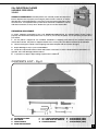
2. Finish removing the contents of the shipping crate and compare with the contents list.(Fig.2)
3. Report damage, if any to your local distributor.
4. Clean all rust protected surfaces with a mild solvent or kerosene. Do not use lacquer thinner; paint thinner, or
gasoline. These will damage painted surfaces.
5. To prevent rust, apply a light coating of paste wax to surface.9
CONTENTS LIST - Fig.2
A. CUTTERHEAD GUARD
B. DUST HOOD
C. SAFETY HANDLE
D. KNIFE SETTING GAUGE
E. 12 X 14MM OPEN END WRENCH
F. 10 X 8MM OPEN END WRENCH
G. T-HANDLE WRENCH
H. ALLEN WRENCH (4MM)
I. ALLEN WRENCH (5MM)
J. ALLEN WRENCH (6MM)
3
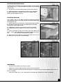
INSTALLATION
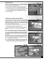
FIG. 3
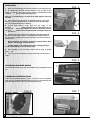
1. Remove the fastening bolts from the machine to the shipping skid.
2. Two lifting lugs are built into the machine, one of which is illustrated in (Fig.3,A). These lugs can be used to mechanically lift the
machine using a forklift and lifting straps.
Note: The second lifting lug is located at the back opposite end of the
machine.
3. Table can be lowered (Fig.3,B) to facilitate cleaning, loosen lock
knob (C) and turn handwheel (D) counter-clockwise until the table (B) is at the desired height for cleaning.
4. Loosen and remove screw from the top edge of the
machine
(Fig4,E). Raise the top cover as illustrated in (Fig.5,F)
this step will
expose the chipbreakers, and the cutterhead. Note: The
top cover
ofthemachineishingedtofacilitatecleaningandadjustment
procedures
5. Carefully remove the protective coating from the table, table rolls, infeed roll, anti-kickback fingers, cutterhead and cutterhead knives. This protective coating may be removed with a soft cloth moistened with kerosene.
FIG. 4
• Never attempt to use Gasoline, Acetone or Lacquer thinner, these
products will damage any painted areas.
• Caution: Extreme care should be taken when cleaning the knives,
as the cutterhead knives are extremely sharp.
6. After cleaning, cover the table surface with a layer of quality
paste wax.
7. Lower top cover and replace locking screw that was removed in
step 4.
FIG. 5
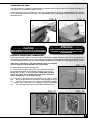
ASSEMBLING HANDWHEEL HANDLE
Thread handle assembly (A) Fig.6 into handwheel (B) and tighten locknut
(C).
ASSEMBLING CUTTERHEAD GUARD
Position the cutterhead guard (A) Fig.7, on the top cover of machine.
Align holes in cutterhead guard with holes in top cover and fasten with
(six) 6mm-button head screws (B) as illustrated in Fig.7◊
FIG. 6
4
FIG. 7
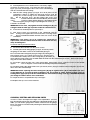
ASSEMBLING DUST HOOD
A dust hood with a 5» opening is supplied with your machine and is to be used when connecting the planer to a
dust collector or a central dust collection system.
Position dust hood (A) Fig.8, against the rear of the machine and on the top of cutterhead guard (B). Align the
holes and fasten the dust hood (A) Fig.9, to the cutterhead guard (B) using eight 6mm-button head screws (C) as
illustrated in Fig.9.
FIG. 8
•••••••• CAUTION! ••••••••
NEVER ATTEMPT TO CONNECT TO AN OUTLET WITH A
GREATER POWER SOURCE VOLTAGE THAN REQUIRED!
FIG. 9
•••••••• ATTENTION! ••••••••
ALWAYS VERIFY THAT THE MACHINE IS PROPERLY
GROUNDED TO AVOID ELECTRIC SHOCK TO THE
WORK OPERATOR!
ELECTRICAL CONNECTIONS & REQUIREMENTS
Before connecting the planer to the power source verify that the voltage supplied corresponds as specified on the
nameplate of the machine. A power source with greater voltage than needed can result in serious injury to the user
as well as damage the machine. If in doubt, contact a qualified electrician before connecting to the power source.
NOTE: Power cord and plug is not shipped with the planer. The standard
machine shipped wired for 220/440 or 575 volt operation.
FIG. 10
To wire the planer follow the following steps:
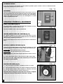
1. Loosen screw (A) Fig.10, and remove cover (B) from the terminal
box located at the back of the machine. Bring the power line up
through hole (C) Fig.11, in the terminal box. NOTE: Strain relief and
power cord clamps are not supplied with the machine. Remove the plastic shield (D) Fig.11, from terminal strip (E)
2. Connect the three power lines to terminals F,G, & K Fig.12, along
with the green ground wire to terminal H. After applying power to
the
machine, turn the power off to check if the machine is rotating
correctly. If the cutterhead is not rotating correctly, interchange
any two of the three power lines connected to terminals F,G & K.
FIG. 11
FIG. 12
5
CHANGING VOLTAGE
If you must reconnect your machine for 220 or 440-volt operation, please contact or have a certified electrician
connect the machine to the power source.
GROUNDING
FIG. 13
Machine must be properly grounded in order to avoid electric shock to
the work operator. The use of an extension cord is not recommended,
if necessary use a three-prong extension cord and outlet (immediately
replace the extension cord if worn out, cut or damaged). If in doubt
contact a qualified electrician.
OPERATING CONTROLS & ADJUSTMENTS
START / STOP SWITCH (Fig.13)
The power switch is located on the left side of the machine. Press the
green button «On» to start the machine (A)
Press the red button «Off» to stop the machine (B)
FIG. 14
LOCKING SWITCH IN THE «OFF» POSITION (Fig.14)
We suggest to padlock or use a pin to lock the start button (C) when
machine is not in use, this will prevent unauthorized use and additional
safety when the machine is turned «Off».
Insert a pin through the two holes in the start button as illustrated in
Fig.14.
RAISING & LOWERING THE TABLE (Fig.15)
Adjustment to the table height can be made by loosening lock knob
(A) and rotating the raising and lowering of table with handwheel (B).
FIG. 15
To raise table: turn the handwheel (B) clockwise.
To lower table: turn the handwheel (B) counter-clockwise.
Tighten lock knob (A), after table height adjustment is made in order to
lock in position.
The metric table height scale (C) will indicate the table height setting.
Note: For best results, setting of the table should always be made from
the bottom to upward position.
ADJSTING FEED SPEED (Fig.16)
1. The feed speed for the planer is variables from 20 to 38.7 FPM.
2. Use the speed selector knob (A); in order to change the feed speed.
3. Turn the speed selector knob clockwise to decrease the feed
speed. Turn counter-clockwise to increase feed speed.
Important: Never change the feed speed when machine is stopped;
change the feed speed only while the machine is running.
6
FIG. 16
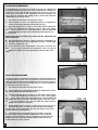
TABLE ROLLS (Fig.17)
The planer is equipped with two-table rolls (A); which aid in feeding the
stock. This will reduce friction between the stock and the table and will
rotate as the stock is fed through the planer.
1. To raise the table rolls, loosen lock lever (B) as illustrated in Fig.17
and pull control lever (C) upwards to the required height setting.
FIG. 17
2. To lower the table rolls, loosen locking lever (B) and push the
control lever (C) downwards to the required height setting.
3. After adjusting height of the table roll, tighten the lock lever (C) in
order to lock in position.
CHECKING AND ADJUSTING TABLE ROLL HEIGHT
It is not possible to give the exact dimensions on the proper height
setting of the table rolls because each type of wood has different
behavioral patterns. As a general rule, when planing rough stock,
the table rolls should be set high (.003» to .005») above the table
surface. When planing finish stock, the table rolls should be set low
(.001») above or level with the table surface.
FIG. 18
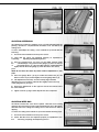
To verify and adjust the height of the table rolls, proceed as follows:
1. Disconnect the machine from the power source.
2. With the table rolls in the lowest position, place a straight edge (A) Fig.18, across both table rolls (B) or the left side of the table as
shown.
3. With a feeler gauge (B) Fig.19, measure the gap between the
table surface and the straight edge (A) near the infeed roll (C).
4. If adjustment to the infeed table roll is necessary, loosen the locknut (D) Fig.20; located under the table and below the infeed roll and
rotate adjustment nuts (E) as required to raise or lower the height of the infeed roll.
FIG. 19
NOTE: it will be necessary to raise the table in order to gain access to
the adjustment nuts. Tighten locknut (D) after adjustment is made.
5. Verify and adjust the height of the infeed table roll or the other
side of the table in the same manner.
6. To check the height of the outfeed table roll, proceed as follows: with a feeler gauge (B) Fig.21, measure the gap between the table
surface and the straight edge (a) near the outfeed roll(F).F
FIG. 20
FIG. 21
7
7. If an adjustment to the outfeed table roll is necessary loosen lock- nut (G) Fig.22, located under the table below the outfeed table roll (F). Rotate the adjustment nuts (H) as required; in order to raise or
lower the height of the outfeed roll (F).
FIG. 22
NOTE: it will be necessary to raise the table in order to gain access to the
adjustment nuts. Tighten locknut (G) once adjustments are completed.
8. Verify and adjust the height of the outfeed table roll on the other
side of the table in the same manner.
ANTI-KICKBACK FINGERS (FIG.23)
FIG. 23
A series of anti-kickback fingers (A), are provided on the infeed end of
the planer to prevent kickback of the workpiece during planing operations. These anti-kickback fingers operate by gravity and no adjustment
is required. It is necessary, however to inspect them occasionally to
make sure they are free of gum and pitch and that they are operated
independently and freely.
WARNING: When inspecting or cleaning the anti-kickback fingers;
make sure the machine is turned «OFF» and disconnected from the
power source.
VERIFY AND ADJUST DRIVE BELT TENSION (FIG.24)
FIG. 24
Proper belt tension is correct when there is approximately 1/4» deflection, using light finger pressure on the drive belts (A) Fig.24, midway
between pulleys. If adjustments are required proceed as follows:
1. Disconnect the machine from the power source.
2. Loosen and tighten the two adjustment nuts (C), in order to move
motor plate up or down as needed to increase or decrease the
drive belt tension. Tighten both adjustment nuts (C) against plate
(D) once adjustments are completed.
3. Close both side panels.
•••••••• CAUTION! ••••••••
KNIVES ARE EXTREMELY SHARP, PLEASE PROCEED WITH CAUTION WHEN REPLACING OR REMOVING!
CHECKING, RESETTING AND REPLACING KNIVES
When checking, resetting and replacing knives, proceed as follows:
1. Disconnect the machine from the power source.
2. Remove the locking screw and raise top cover (A) Fig.25, to reveal cutterhead (B)
3. Carefully place knife setting gauge (C) Fig.26 & 27, in order to
position the gauge on the radius section of the cutterhead (B).
When set correctly, knife (D) Fig.26 & 27, should slightly contact the
bottom of the insert section(E) Fig.27 of knife gauge (C) which is
set at .070». Verify the remaining knives in the same manner.
8
FIG. 25
4. If an adjustment to one or all three knives is necessary, slightly
loosen the 12 locking screws, 10 of which are shown in Fig.26 &
Fig.27 (F) loosen just enough to relieve stress in the cutterhead (B)
and do not disturb the knife setting.
FIG. 26
5. With the knife setting gauge (C) Fig.26 & 27 still in place on the
cutterhead, continue to adjust the knife that must be reset by
turning the 12 knife locking screws CLOCKWISE until knife locking
bar (G) becomes loose. The lifter springs and screws (not
shown)
located under the knife will automatically raise the knife
until it
comes in contact with the gauge (C). Then tighten up the
knife locking bar (G) Fig.26 & Fig.27, by turning the ten screws (F)
COUNTER - CLOCKWISE.
IMPORTANT: At this time, only tighten the knife locking bar (G) just
enough to hold the knife (D) in position inside the cutterhead slot.
6. If other knives need adjustment, repeat step 5.
7. After all the knives are positioned in the cutterhead with the
knife
locking screws tighten and , turn each of the 12 locking screws
(F)
Fig.26, COUNTER-CLOCKWISE until the knives are secure in the
cutterhead.
FIG. 27
IMPORTANT: If the knives are to be removed for sharpening or
replacement, extreme caution must be taken as the knives are very
sharp and dangerous.
To remove: Knives proceed as follows:
8. Disconnect the machine from the power source .
9. Carefully place knife setting gauge (C) Fig.26, in order to position
the gauge on the radius section of the cutterhead (B) Fig.27.
10. Loosen the knife locking bar (G) Fig.26 & Fig.27, by turning the 12
knife locking screws; 10 of which are shown in (F). Turn the screws
CLOCKWISE and carefully remove the locking bar (G) and knife (D) along with the springs and screws located under the knife from the cutterhead (not shown) . Remove the remai-
ning knives in the same manner.
11.Thoroughly clean the knife slots, knife locking bars, and locking screws. Verify the screws; if the threads
appear worn or stripped, or if the heads are damaged replace immediately.
12. Carefully replace the springs and screws (not shown) knives (D) Fig.27, and the knife locking bars (G) into the three slots in the cutterhead (B).
IMPORTANT: When replacing the knife locking bars (G) Fig.27 against knives (D) as illustrated in the cross
section diagram. Be sure that the knife locking bars (G) are installed as shown, with the locking screws (F)
holding knives (D) properly inside the cutterhead slots. Turn all knife locking screws(F), COUNTER-CLOCKWISE
just enough to hold the knives in the cutterhead.
13. Adjust the knives as explained in Step 3 through 7.
14. Replace the top cover on the machine.
FIG. 28
CHECKING, RESETTING AND REPLACING KNIVES
In order to check and adjust the height of the chipbreaker , pressure
bar, infeed and outfeed rolls and adjust the cutterhead parallel to the
table, you will need a gauge block made of hard wood. The gauge
block can easily be constructed by following the dimensions illustrated
to you in Fig.28.
O
9
ADJUSTING CHIPBREAKERS
The chipbreakers (A) Fig.29, are located on the top of the planer and
extend downward around the front of the cutterhead. The chipbreakers
will raise as stock is fed through the planer and «breaks or cuds» the
wood chips. The bottom of the chipbreakers must be parallel to the
knives and set .40» below the cutting circle. To check and adjust the
chipbreakers, proceed as follows:
FIG. 29
1. Disconnect the machine from the power source.
2. Make certain the knives are adjusted properly as explained in
section «Checking, Replacing and Resetting Knives».
3. Place the gauge block (B) Fig.30, on the table surface and directly under the cutterhead as illustrated. Using a .040» feeler gauge
(C)
Fig.30, position on top of the gauge block, raise the table until
cutterhead knife (D) touches the feeler gauge when the knife is at
its lowest point.
NOTE: Do not move the table any further until the adjustment has
been completed.
FIG. 30
4. Move gauge block (B) Fig.31, directly under the chipbreaker (A)
as illustrated. The bottom of the chipbreakers (A) Fig.31, should slightly touch the gauge block (B).
5. If an adjustment to the chipbreaker is necessary, loosen the two
hex nuts (E) Fig.29, and turn the adjustment screws (F) until the
chipbreaker slightly touches the gauge block at both sides of the
table.
FIG. 31
ADJUSTING PRESSURE BAR
The pressure bar is located directly behind the cutterhead and rides on
the planed surface of the stock, pressing the stock downwards on the
table. The pressure bar must be parallel to the knives and in contact to
the table and set .010» below the cutting circle. To verify and adjust the
pressure bar, proceed as follows:
1. Disconnect the machine from the power source.
2. Verify that the knives are adjusted properly as explained in section «Checking, Adjusting and Replacing Knives».
3. Position the gauge block (B) Fig.32, on the table surface directly
under the cutterhead as illustrated. Use a .010» feeler gauge
(C)
Fig.32, place on the top of the gauge block, raise the table until
the cutterhead knife (D) touches the feeler gauge when the knife is
at
its lowest point. Do not move the table any further until the
adjustment has been completed.
4. Move gauge block (B) Fig.33, under the pressure bar (D) as
illustrated. The bottom of the pressure bar (D) Fig.33 should slightly
touch the top of the gauge block (B). Verify the opposite end of the pressure bar in the same manner.
5. If an adjustment to the height of the pressure bar is necessary;
loosen lock nut (E) Fig.34, and turn adjustment screw (F) until the
bottom of the pressure bar (D) Fig.33 slightly touches the top of the gauge block (B). Repeat the adjustment at the other end of the
pressure bar in the same manner.
10
FIG. 32
FIG. 33
ADJUSTING OUTFEED ROLL
The outfeed roll continues to feed the stock out of the machine after the
planing operation is completed and should be set at .030» below the
cutting circle.
FIG. 34
FIG. 35
To check and adjust the setting of the outfeed roll, proceed with the
following:
1. Disconnect the machine from the power source.
2. Verify that the knives are adjusted properly as explained in
«Checking, Adjusting and Replacing Knives».
3. Place the gauge block (A) Fig.35 on the table, directly under
the
cutterhead (B). Using a .030» feeler gauge (C) place on the top
of
the gauge block (A), raise the table until the cutterhead knife
slightly touches the feeler gauge (A) when the knife is at its lowest
point.
NOTE: Do not move the table any further until the adjustment is complete.
FIG. 36
4. Place the gauge block (A) Fig.36, under the outfeed roll (D). The
bottom of the roll (D) should slightly touch the gauge block (A).
5. If an adjustment is necessary, loosen locknut (E) Fig.37 and turn
adjustment screw (F) until the outfeed roller slightly touches the top of the gauge block (A) Fig.36.
6. Repeat the adjustment on the opposite end of the outfeed roll in
the same manner.
7. Tighten locknuts (E) Fig.37 after adjustments are completed.
ADJUSTING INFEED ROLL
FIG. 37
The infeed roll feeds the stock into the planer while the stock is being
surfaced. The infeed roll must be positioned uniformly across the planer
and 040» below the cutting the cutting circle of the feed stock without
slipping.
To check the setting of the infeed roll, proceed with the following steps:
1. Disconnect the machine from the power source.
2. Check that the knives are adjusted properly as explained in section «Checking, Adjusting and Replacing Knives «.
11
3. Place the gauge block (A) Fig.38 on the table, directly under the
cutterhead (B). Use a .040» feeler gauge (C) and place on top
of
the gauge block (A), raise the table until the cutterhead knife
slightly touches the feeler gauge (A) when the knife is at its lowest
point. Note: Do not remove the table any further until the adjustment is complete.
FIG. 38
4. Place the gauge block (A) Fig.39, under infeed roll (D). The bottom of the roller (D) should slightly touch gauge block (A).
5. If adjustments are necessary, loosen locknut (E) Fig.40, and turn
adjustment screw (F) until the infeed roll slightly touches the top of
the gauge block (A).
6. Repeat the adjustments on the opposite end of the infeed roller in
the same manner.
7. Tighten locknuts (E) Fig.40, after adjustments are completed.
FIG. 39
LEVELLING THE TABLE
The table is set parallel to the cutterhead at the factory and no further
adjustment should be necessary.
To check if the table is level with the cutterhead, proceed with the following steps:
1. Disconnect the machine from the power source.
2. Check if the cutterhead knives are correctly set as explained in
«Checking, Adjusting and Replacing Knives».
3. Verify that the table is set parallel to the cutterhead by placing a
gauge block (A) Fig.41 directly under the cutterhead on the left
hand side of the table as illustrated. Raise the table until the gauge block (A) Fig.41, slightly touches the cutterhead.
FIG. 40
4. Carefully move the gauge block (A) Fig.42, to the right hand side
of the table directly under the cutterhead. The distance from the
table to the cutterhead should be identical.
5. If the table is not parallel to the cutterhead, lower boot (B) Fig.43,
which is located underneath the table. NOTE: Table elevating hand-
wheel must be unlocked when making this adjustment.
6. Loosen lock screw (C) Fig.43, and with large pliers (D) turn adjust
ment sleeve (E) as required until table is parallel with the cutterhead. Tighten lock screw (C) after adjustment is completed and replace boot (B).
Ã
12
NOTE: The same adjustment can also be made on the other side of the planer if necessary.
FIG. 41
FIG. 42
ADJUSTING TABLE HEIGHT SCALE
The table height scale indicates the distance the table is from the cutting
circle (depth of cut). To verify and adjust the pointer, proceed with the
following steps:
FIG. 43
1. Run a piece of wood through the planer and stop the machine.
2. Measure the thickness of the planed end of the stock as illustrated
in Fig.44. If adjustment is required, loosen screw (A) Fig.45, adjust
pointer (B) and re-tighten screw (A).
ADJUSTING TABLE GIBS
In he unlikely event of the table developing unwanted movement
during planing operations, the table can be checked and adjusted by
following these steps:
1. With the table in the locked position, and a feeler gauge; measure the gap between table gib (A) Fig.46 and table bracket (B). When
set properly the gap should be .005»
2. If adjustment is required, loosen the three locknuts (C), and turn
three adjustment screws (D) Fig.46, as necessary to set the correct
gap.
FIG. 44
3. Check and adjust the gap on the other side of the table in the
same manner. After adjustments are completed, tighten the six locknuts,
three of which are illustrated in (C) Fig.46.
4. Raise and lower the table to its fullest range and check to see if
the table moves up and down without binding.
FIG. 45
FIG. 46
MAINTENANCE
•
Disconnect the machine from the power source.
•
Planer knives must be sharpened when use after numerous projects.
• Periodic lubrication should be performed with grease or machine oil to assure the durability and accuracy of the use of machine.
•
Always dust off dirt, chips, or any other particles left behind after operations have been completed.
13
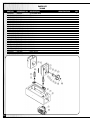
PARTS LIST
30-460
14
PART N0.
REFERENCE NO. DESCRIPTION
30460-A01
30460-A02
30460-A03
30460-A04
30460-A05
30460-A06
30460-A07
30460-A08
30460-A09
30460-A10
30460-A11
30460-A12
30460-A13
30460-A14
30460-A15
30460-A16
30460-A17
30460-A18
30460-A19
30460-A20
30460-A21
30460-A22
C003016
C003017
G002008
S284008
S137005
C002024
S273042
T004034
S277006
C034031
C067064
C015017
S282009
S274006
S201006
C051080
P026003
S213014
P031001
P031006
C078003
C081004
(L) COLUMN BASE
(R) COLUMN BASE
ELEVATING SCREW
SPRING WASHER
SCREW
BASE
NUT
MOTOR ASS’Y
NUT
SHAFT
SPROCKET SHAFT
HUB
WASHER
SPRING WASHER
SCREW
BUSHING
HANDWHEEL
SET SCREW
HANDLE
KNOB
BOOT
DEPTH SCALE
SPECIFICATION
10.2 x 18.8 x 3.9 x 3.0T
M10-P1.5 x 30L
M10-P1.5
M12-P1.75
6.4 x 13 x 1.0T
6.1 x 12.2 x 2.7 x 1.5T
M6-P1.0 x 25L
M8-P1.25 x 10L
5/16» x 2» L
3/8» x 90L
QTY
1
1
1
28
16
1
12
1
2
1
1
1
3
3
3
1
1
1
1
1
2
1
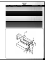
PARTS LIST
30-460
PART N0.
REFERENCE NO. DESCRIPTION
30460-B01
30460-B02
30460-B03
30460-B04
30460-B05
30460-B06
30460-B07
30460-B08
30460-B09
30460-B10
30460-B11
30460-B12
!
30460-B13
G003013
C007001
T013027
C020003
C051019
S284014
S136007
S136003
S213006
S273041
C015022
S282011
S136004
WORK TABLE
TABLE GUIDE
ROLLER
GUIDE
COLLOR
SPRING WASHER
SCREW
SCREW
SCREW
NUT
SUPPORT
WASHER
SCREW
SPECIFICATION
QTY
1
1
4
1
1
6
6
1
1
1
2
2
1
15
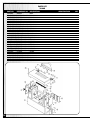
PARTS LIST
30-460
16
PART N0.
REFERENCE NO. DESCRIPTION
30460-C01
30460-C02
30460-C03
30460-C04
30460-C05
30460-C06
30460-C07
30460-C08
30460-C09
30460-C10
30460-C11
30460-C12
30460-C13
30460-C14
30460-C15
30460-C16
30460-C17
30460-C18
30460-C19
30460-C20
30460-C21
30460-C22
30460-C23
30460-C24
30460-C25
30460-C26
30460-C27
30460-C28
30460-C29
30460-C30
30460-C31
Â
30460-C32
T001034
S284008
S203006
C015029
C015096
C046073
C015032
C015097
T010015
S273042
S203008
C060007
C053022
T011007
C060012
C042035
C046055
C034023
S273041
S202009
C060009
C053023
T009032
C046016
S213014
T009034
C060014
S246004
P054010
O056011
C034021
C060040
CUTTERHEAD ASS’Y
SPRING WASHER
SCREW
BRACKET (L)
BRACKET (R)
SHAFT
BRACKET (L)
BRACKET (R)
INFEED ROLLER ASS’Y
NUT
SCREW
SPRING WASHER
SPECIAL WASHER
BEARING BLOCK
SPRING
PRESSURE BAR
SCREW
STUD (125mm)
NUT
SCREW
SPRING
SPECIAL WASHER
CHIPBREAKER ASS’Y
PIN
SET SCREW
ANTI-KICKBACK ASS’Y
SPRING
SCREW
KNIFE
LOCKING BAR
STUD
;
SPRING
SPECIFICATION
10.2 x 18.4 x 3.7 x 2.5T
M10-P1.5 x 30L
19.05 x 678L
M10-P1.5
M10-P1.5 x 40L
6.35 x 62L
M10-P1.5 x 125L
M8-P1.25
M8-P1.25 x 40L
3/8» x 45L
M8-P1.25 x 10L
M5-P0.8 x 16L
24»
24»
M10-P1.5 x 90L
QTY
1
14
16
1
1
2
1
1
1
14
4
2
4
1
2
1
2
2
2
2
2
6
1
2
2
1
6
6
3
3
2
2
PARTS LIST
30-460
PART N0.
REFERENCE NO. DESCRIPTION
30460-D01
30460-D02
30460-D03
30460-D04
30460-D05
30460-D06
30460-D07
30460-D08
30460-D09
30460-D10
30460-D11
30460-D12
30460-D13
30460-D14
30460-D15
30460-D16
30460-D17
30460-D18
30460-D19
30460-D20
{
30460-D21
G006011
S282011
S284008
S137005
T017006
S137004
S277005
C067017
S026126
S298074
C039004
S298008
S293043
T004035
S282010
S284007
S202006
C023069
S282009
S284006
S201004
GEAR BOX ASS’Y
WASHER
SPRING WASHER
SCREW
LINK ASS’Y
SCREW
NUT
CHAIN GEAR
BALL BEARING
RETAINING RING
SHAFT
EXT. RETAINING RING
NUT
VARIABLE FEED PULLEY ASS’Y
WASHER
SPRING WASHER
SCREW
SUPPORT
WASHER
SPRING WASHER
SCREW
SPECIFICATION
10.5 x 25 x 2T
10.2 x 18.4 x 3.7 x 2.5T
M10-P1.5 x 30L
M10-P1.5x 25L
M10-P1.5
6203ZZ 17 x 40 x 12
40 x 1.95
17 x 1.15
M12-P1.75
8.4 x 16 x 1.5T
8.2 x 15.4 x 3.2 x 2.0T
M8-P1.25 x 25L
6.4 x 13 x 1.0T
6.1 x 12.2 x 2.7 x 1.5T
M6-P1.0 x 16L
QTY
1
8
6
4
1
3
2
1
1
1
1
1
1
1
4
4
4
1
2
2
2
17
PARTS LIST
30-460
18
PART N0.
REFERENCE NO. DESCRIPTION
30460-E01
30460-E02
30460-E03
30460-E04
30460-E05
30460-E06
30460-E07
30460-E08
30460-E09
30460-E10
30460-E11
30460-E12
30460-E13
30460-E14
30460-E15
30460-E16
30460-E17
30460-E18
30460-E19
30460-E20
30460-E21
30460-E22
30460-E23
30460-E24
30460-E25
30460-E26
T020038
C073079
C061001
S284014
S136005
C061002
S136008
S273041
C078011
S284006
S201011
C023051
C077024
C073082
P027003
C073010
C073017
C074214
C039005
C053021
S284009
S138009
S273043
S326003
S3216009
S202019
BASE
TOP COVER
TOP COVER BRACKET
SPRING WASHER
SCREW
HINGE
SCREW
NUT
CHIP DISCHARGE COVER
SPRING WASHER
LOCKING SCREW
DUST CHUTE
DUST HOOD
(L) COVER
SAFETY HANDLE
(R) BASE COVER
(R) COVER
REAR COVER
BUSHING
WASHER
SPRING WASHER
SCREW
NUT
BAFFLE SEAL
SEAL
STUD
SPECIFICATION
8.5 x 15.6 x 3.2 x 2.5T
M8-P1.25 x 30 L
M8-P1.25x50L
M8-P1.25
6.1 x 12.2 x 2.7 x 1.5T
M6-P1.0 x 45L
12.2 x 21.5 x 4.2 x 3.0T
160mm
QTY
1
2
4
4
2
2
2
1
38
38
1
1
1
2
1
1
2
2
4
2
2
2
1
1
PARTS LIST
30-460
PART N0.
REFERENCE NO. DESCRIPTION
30460-F01
30460-F02
30460-F03
30460-F04
Ü
30460-F05
C015094
T016008
S284014
S202006
T003003
PLATE
LEVEL GEAR
SPRING WASHER
SCREW
LEVEL SCREW
SPECIFICATION
QTY
8.5 x 15.6 x 3.3 x 2.5T
1
1
10
10
2
19
PARTS LIST
30-460
20
PART N0.
REFERENCE NO. DESCRIPTION
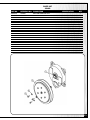
30460-G01
30460-G02
30460-G03
30460-G04
30460-G05
30460-G06
30460-G07
30460-G08
30460-G09
30460-G10
30460-G11
@
30460-G12
T012029
C017014
C057006
S273043
S282011
P028001
S214006
S273042
C070003
S282008
S202002
P031004
TABLE WHEEL
HUB
LEVER
NUT
WASHER
LOCK LEVER
SET SCREW
NUT
POINTER
WASHER
SCREW
KNOB
SPECIFICATION
M12-P1.75
10.5 x 25 x 2.0T
M10-P1.5 x 30L
M10-P1.5
5.3 x 10 x 1T
M5-P0.8 x 10L
QTY
1
1
1
1
1
1
6
6
1
1
1
1
PARTS LIST
30-460
PART N0.
REFERENCE NO. DESCRIPTION
30460-H01
30460-H02
30460-H03
30460-H04
T014002
T015008
S284007
S136004
REDUCER GEAR BOX ASS’Y
GEAR PULLEY ASS’Y
SPRING WASHER
SCREW
SPECIFICATION
QTY
8.2 x 15.4 x 3.2 x 2.0T
M8-P1.25 X25l
1
1
1
1
21
PARTS LIST
30-460
22
PART N0.
REFERENCE NO. DESCRIPTION
30460-I01
30460-I02
30460-I03
30460-I04
30460-I05
30460-I06
30460-I07
30460-I08
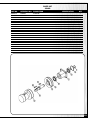
30460-I09
30460-I10
30460-I11
30460-I12
30460-I13
30460-I14
30460-I15
30460-I16
C011023
C009054
S026048
C009053
C010026
S284006
S135003
C010028
C064124
S003179
C053003
S284008
S137021
C064128
S003180
S137004
CUTTERHEAD
(R) SUPPORT
BEARING
(L) SUPPORT
(R) SUPPORT
LOCK WASHER
SCREW
(L) COVER
PULLEY
KEY
WASHER
SPRING WASHER
SCREW
PULLEY
KEY
SCREW
SPECIFICATION
6008ZZ, 40 x 68 x 15
6.1 x 12.2 x 2.7 x 1.5T
M6-P1.0 X 20L
8 x 8 x 65L
48 x 11 x 5.0T
10.2 x 12.2 x 3.7 x 2.5T
M10-P1.5 x 20L
8 x 8 x 70L
M10-P1.5 x 25L
QTY
1
1
4
1
1
6
6
1
1
1
2
2
1
1
1
1
PARTS LIST
30-460
PART N0.
REFERENCE NO. DESCRIPTION
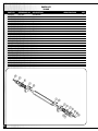
30460-J01
30460-J02
30460-J03
30460-J04
30460-J05
30460-J06
30460-J07
C009021
P051001
S043005
C035001
C028001
S267168
C037002
SUPPORT
BEARING
THRUST BEARING
SHAFT
GEAR
SPRING PIN
COLLAR
SPECIFICATION
19.05 x 22.2 x 25 x 18L
(2904) 20 x 35 x 10
5 x 40L
QTY
1
1
1
1
1
1
1
23
PARTS LIST
30-460
24
PART N0.
REFERENCE NO. DESCRIPTION
30460-K01
30460-K02
30460-K03
30460-K04
30460-K05
30460-K06
30460-K07
30460-K08
30460-K09
30460-K10
30460-K11
@
30460-K12
P041008
C064125
S214006
C063003
S282011
S284008
S137019
S273042
C049001
C034030
S282012
S273043
MOTOR
MOTOR PULLEY
SET SCREW
MOTOR BRACKET
WASHER
SPRING WASHER
SCREW
NUT
BRACKET
ADJ.SCREW
WASHER
NUT
SPECIFICATION
QTY
3HP 1PH
1
1
2
1
3
6
6
6
1
1
2
4
M10-P1.5 x 30L
10.5 x 25 x 2T
10.2 x 18.4 x 3.7 x 2.5T
M10-P1.5 x 45L
M10-P1.5
13 x 21 x 2.5T
M12-P1.75
PARTS LIST
30-460
PART N0.
REFERENCE NO. DESCRIPTION
30460-L01
30460-L02
30460-L03
30460-L04
30460-L05
30460-L06
30460-L07
30460-L08
30460-L09
30460-L10
30460-L11
C009067
S026042
S026123
S298080
C047078
S298015
S004172
C064129
S212001
S003077
P050001
HOUSING
BEARING
BEARING
RETAINING RING
PULLEY SHAFT
RETAINING RING
KEY
PULLEY
SCREW
KEY
VARIABLE PULLEY
SPECIFICATION
6006ZZ 30 x 62 x 16
6205ZZ 25 x 52 x 15
52 x 2.2
25 x 1.35
8 x 8 x 30L
M6-P1.0 x 10L
6 x 6 x 40
QTY
1
1
1
1
1
1
6
6
6
6
1
25
PARTS LIST
30-460
26
PART N0.
REFERENCE NO. DESCRIPTION
30460-M01
30460-M02
30460-M03
30460-M04
30460-M05
30460-M06
30460-M07
30460-M08
Æ
30460-M09
C042009
C060008
S282010
S136004
C048037
C015095
S284009
S204004
C015031
CHIP BREAKER
SPRING
SPRING WASHER
SCREW
SHAFT
SUPPORT (L)
SPRING
SCREW
SUPPORT (R)
SPECIFICATION
8.4 x 15.5 x 1.6T
M8-p1.25 x 25L
12.2 x 21.5 x 4.2 x 3.0T
M12-P1.75 x 30L
Ä
QTY
12
12
12
12
2
1
4
4
1
PARTS LIST
30-460
PART N0.
REFERENCE NO. DESCRIPTION
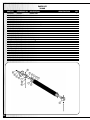
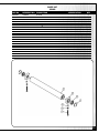
30460-N01
30460-N02
30460-N03
30460-N04
C046073
C052077
C045012
C052014
FINGER ROD
FINGER
COLLAR
BUSHING
SPECIFICATION
QTY
19.05 x 678L
1
47
47
2
27
PARTS LIST
30-460
28
PART N0.
REFERENCE NO. DESCRIPTION
30460-O01
30460-O02
30460-O03
30460-O04
30460-O05
30460-O06
30460-O07
30460-O08
30460-O09
30460-O10
30460-O11
30460-O12
30460-O13
30460-O14
30460-O15
30460-O16
C039027
C038006
S318021
C051023
S213001
C009017
C009049
P051002
C067014
S003073
S282049
S284008
S137021
C034022
S273042
S319012
INFEED SHAFT
INFEED ROLL
RUBBER BUSHING
BUSHING
SET SCREW
BEARING BLOCK (R)
BEARING BLOCK (L)
BEARING
SPROCKET
KEY
WASHER
SPRING WASHER
SCREW
STUD (165mm)
NUT
Ü
OIL CAP
SPECIFICATION
M8-P1.25 x 12L
30 x 36 x 38L
6 x 6 x 25L
11 x 38 x 2T
10.2 x 18.4 x 3.7 x 2.5T
M10-P1.5 x 20L
M10-P1.5 x 165L
M10-P1.5
QTY
1
24
96
2
4
1
1
2
1
1
1
1
1
2
2
2
PARTS LIST
30-460
PART N0.
REFERENCE NO. DESCRIPTION
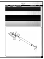
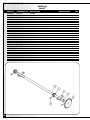
30460-P01
30460-P02
30460-P03
30460-P04
30460-P05
30460-P06
30460-P07
30460-P08
30460-P09
30460-P10
30460-P11
@
30460-P12
C039028
C009017
C009049
P051002
C067015
S003073
S282049
S284008
S137021
C034087
S273042
S1319012
OUTFEED ROLLER
BEARING
BEARING
BEARING
SPROCKET
KEY
WASHER
SPRING WASHER
SCREW
STUD (105mm)
NUT
OIL CAP
SPECIFICATION
30 x 36 x 38L
6 x 6 x 25L
11 x 38 x 2T
10.2 x 18.4 x 3.7 x 2.5T
M10-P1.5 x 20L
M10-P1.5 x 105L
M10-P1.5
QTY
1
1
1
2
1
1
1
1
1
2
2
2
29
PARTS LIST
30-460
30
PART N0.
REFERENCE NO. DESCRIPTION
30460-Q01
30460-Q02
30460-Q03
30460-Q04
30460-Q05
30460-Q06
30460-Q07
30460-Q08
30460-Q09
30460-Q10
30460-Q11
30460-Q12
30460-Q13
30460-Q14
30460-Q15
C006054
C015018
S201004
C017013
C046076
S267168
C051008
S213015
C046010
C049011
C049010
C051022
S282010
S284014
S136003
TABLE
SUPPORT
SCREW
ROD
SPRING PIN
ARM
BUSHING
SET SCREW
SHAFT
LINK SHORT
LINK LONG
ADAPTER
WASHER
SPRING WASHER
°
SCREW
SPECIFICATION
QTY
M6-P1.0 x 16L
1
1
3
2
2
2
2
2
1
1
1
4
4
4
4
5 x 40L
M8-P1.25 x 8L
8.4 x 15.5 x 1.6T
8.5 x 15.6 x 3.3 x 2.5T
M8-P1.25 x 20L
PARTS LIST
30-460
PART N0.
REFERENCE NO. DESCRIPTION
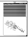
30460-R01
30460-R02
30460-R03
30460-R04
30460-R05
30460-R06
30460-R07
C040039
C009008
S026132
S298080
C051020
S273042
S137020
ROLLER
SUPPORT
BEARING
C-RING
COLLAR
NUT
Ü
SCREW
SPECIFICATION
6205ZZ 25 x 52 x 15
52 x 2.2
M10-P1.5
M10-P1.5 x 75L
QTY
1
2
2
2
2
2
2
31
PARTS LIST
30-460
32
PART N0.
REFERENCE NO. DESCRIPTION
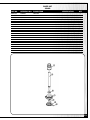
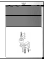
30460-S01
30460-S02
30460-S03
30460-S04
30460-S05
30460-S06
30460-S07
30460-S08
30460-S09
30460-S10
C029003
C039003
S137003
S026135
C031001
S026126
C009022
C067016
S003169
S298019
GEAR
GEAR SHAFT
SCREW 10x206cm
BALL BEARING
GEAR HOUSING
BALL BEARING
GEAR HOUSING PLATE
SPROCKET
KEY
RETAINING RING
SPECIFICATION
M10-P1.5 X20L
6206ZZ 30x62x16
6203ZZ 17x40x12
8 x 8 x 20L
30 x 1.75
QTY
1
1
4
1
1
1
1
1
1
1
PARTS LIST
30-460
PART N0.
REFERENCE NO. DESCRIPTION
30460-T01
30460-T02
30460-T03
30460-T04
30460-T05
30460-T06
30460-T07
30460-T08
30460-T09
30460-T10
30460-T11
30460-T12
30460-T13
30460-T14
C009005
S026129
S026132
C0029007
C064017
C064016
C060020
C051013
S136006
S273041
S00380
S282011
S284007
S136004
HOUSING
BALL BEARING
BALL BEARING
PINION GEAR
PULLEY
PULLEY
SPRING
COLLAR
SCREW
NUT
KEY
WASHER
SPRING WASHER
SCREW
SPECIFICATION
6204ZZ 20 x 47 x 14
6205ZZ 25 x 52 x 15
M8-P1.25 X 50L
M8-P1.25
6 x 6 x 55L
10.5 x 25 x 2.0T
8.2 x 15.4 x 3.2 x 2.0T
M8-P1.25 x 25L
QTY
1
1
1
1
1
1
6
6
6
6
1
1
1
1
33
PARTS LIST
30-460s
34
PART N0.
REFERENCE NO. DESCRIPTION
30460-U01
30460-U02
30460-U03
30460-U04
30460-U05
30460-U06
C015015
P051001
C039026
C028002
S267166
C067018
SUPPORT
BEARING
SHAFT
GEAR
PIN
SPROCKET
SPECIFICATION
19.05 x 22.2
19.05 x 662L
5 x 30L
QTY
2
2
1
2
3
1
PARTS LIST
30-460
PART N0.
REFERENCE NO. DESCRIPTION
30460-V01
30460-V02
30460-V03
30460-V04
30460-V05
30460-V06
30460-V07
30460-V08
30460-V09
30460-V10
30460-V11
C066004
P051001
C052016
S137005
C049018
C015030
C051024
S282011
S284008
S137004
C06001
WHEEL
BEARING
BUSHING
SCREW
LINK
LINK SUPPORT
BUSHING
WASHER
SPRING WASHER
SCREW
SPRING
SPECIFICATION
19.05 x 22.2 x 25 x 18L
M10-P1.5 x 30L
10.5 x 25 x 2.0T
10.2 x 18.4 x 3.7 x 2.5T
M10-P1.25 x 25L
QTY
1
1
1
1
1
1
1
2
2
1
1
35
PARTS LIST
30-460
36
PART N0.
REFERENCE NO. DESCRIPTION
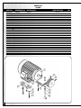
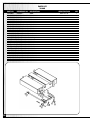
30460-W01
30460-W02
30460-W03
30460-W04
30460-W05
30460-W06
30460-W07
30460-W08
30460-W09
30460-W10
30460-W11
30460-W12
30460-W13
30460-W14
30460-W15
30460-W16
30460-W17
30460-W18
30460-W19
C085001
S284020
S224101
S3114011
S273100
S314012
S224102
S311008
S312003
S282008
S225002
S313001
S225006
S328001
S329003
S317023
S224001
S283004
S317012
SWITCH BOX
SPRING WASHER
RD HD SCREW
SWITCH
SPACER
SWITCH COVER
SCREW
MAGNETIC SWITCH
JUNCTION BOX
WASHER
SCREW
TERMINAL STRIP
SCREW
TIE MOUNTS
CABLE TIE
BUSHING
SCREW
TEETH WASHER
STRAIN RELIEF CLAMP
SPECIFICATION
4.1 x 7 x 1.7 x 1.0T
5/32» - 32NC x 6L
5/32» - 32NC
5/32» - 32NC x 12L
5.3 x 10 x 1.0T
M5-P0.8 x 10L
30A
M5-P0.8 x 20L
20 x 20 x 2
2.5 x 150L
M4-P0.7 x 6L
QTY
1
4
2
1
2
1
2
1
1
4
8
1
2
3
5
3
1
3
3
NOTES
37
30-460
8360, Champ-d’Eau, Montreal (Quebec)
Canada H1P 1Y3
Tel.: (514) 326-1161
Fax : (514) 326-5555
www.general.ca
IMPORTANT: When ordering replacement parts, always give the model number, serial number of
the machine and part number. Also a brief description of each item and quantity desired.