1
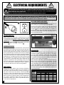
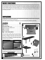
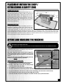
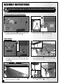
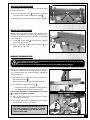
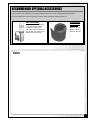
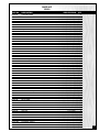
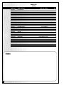
SETUP & OPERATION MANUAL
FEATURES
6" X 108" VERTICAL EDGE BELT SANDER
Tables can be adjusted up or down for full
belt use.
Front table can be inclined left or right.
Innovative hinged dust hood accommodates oversized stock.
Easy adjustment of abrasive belt tension
with one knob only.
Graphite backing reduces belt friction for
longer belt life.
Single knob tracking control.
Auxiliary table allows curved sanding.
Heavy steel base ensures a solid stable
platform while sanding.
Dynamically balanced 7’’ rubber drive
roller and crowned 3’’ idler roller to ensure
solid belt tracking.
Magnetic 2-step safety switch to prevent
unwanted or unintentional start-up is
equipped with an extra-large easy access
stop panel and a lock-out key to prevent
unauthorized use of the sander.
SPECIFICATIONS
BELT SIZE
6" X 108" (152 x 2743 MM)
FRONT TABLE SIZE (L X W)
7 3⁄4” x 37’’ (197 x 940 MM)
AUXILIARY TABLE SIZE (L X W)
11 3⁄4” x 19’’ (299 x 483 MM)
DUST CHUTE OUTLET
4" (102 MM)
BELT SPEED
3150 FPM
BASE DIMENSIONS (L X W)
42” x 16 1⁄2” (1067 x 419 MM)
MOTOR
M1 2 HP, 220 V, 1 PH, 14 A
M2 2 HP, 220 V, 3 PH, 6 A
M3 2 HP, 600 V, 3 PH, 2.5 A
WEIGHT
462 LBS (210 KG)
MODEL
#15-010 M1
VERSION 2_REVISION 1 - JUNE 08/10 (19115210)
© Copyright General® International 06/2010
GENERAL® INTERNATIONAL
8360 Champ-d’Eau, Montreal (Quebec) Canada H1P 1Y3
Telephone (514) 326-1161 • Fax (514) 326-5555 • www.general.ca
THANK YOU
for choosing this General® International model 15-010 6" X 108"
Vertical Edge Belt Sander. This sander has been carefully tested and inspected before shipment and if properly used and maintained, will provide you with years of reliable service. To
ensure optimum performance and trouble-free operation, and to get the most from your
investment, please take the time to read this manual before assembling, installing and operating the unit.
The manual’s purpose is to familiarize you with the safe operation, basic function, and features
of this sander as well as the set-up, maintenance and identification of its parts and components. This manual is not intended as a substitute for formal woodworking instruction, nor to
offer the user instruction in the craft of woodworking. If you are not sure about the safety of
performing a certain operation or procedure, do not proceed until you can confirm, from
knowledgeable and qualified sources, that it is safe to do so.
Once you’ve read through these instructions, keep this manual handy for future reference.
Disclaimer: The information and specifications in this
manual pertain to the unit as it was supplied from the
factory at the time of printing. Because we are committed to making constant improvements, General®
International reserves the right to make changes to
components, parts or features of this unit as deemed
necessary, without prior notice and without obligation to
install any such changes on previously delivered units.
Reasonable care is taken at the factory to ensure that
the specifications and information in this manual corres-
ponds with that of the unit with which it was supplied.
However, special orders and “after factory” modifications may render some or all information in this manual
inapplicable to your machine. Further, as several generations of this model of sander and several versions of
this manual may be in circulation, if you own an earlier
or later version of this unit, this manual may not depict
your machine exactly. If you have any doubts or questions contact your retailer or our support line with the
model and serial number of your unit for clarification.
GENERAL® & GENERAL® INTERNATIONAL WARRANTY
All component parts of General®, General® International and Excalibur by General
International ® products are carefully inspected during all stages of production and each unit
is thoroughly inspected upon completion of assembly.
Limited Lifetime Warranty
Because of our commitment to quality and customer satisfaction, General® and General®
International agree to repair or replace any part or component which upon examination,
proves to be defective in either workmanship or material to the original purchaser for the life
of the tool. However, the Limited Lifetime Warranty does not cover any product used for professionnal or commercial production purposes nor for industrial or educational applications.
Such cases are covered by our Standard 2-year Limited Warranty only. The Limited Lifetime
Warranty is also subject to the “Conditions and Exceptions” as listed below.
Standard 2-Year Limited Warranty
All products not covered by our lifetime warranty including products used in commercial,
industrial and educational applications are warranted for a period of 2 years (24 months) from
the date of purchase. General® and General® International agree to repair or replace any
part or component which upon examination, proves to be defective in either workmanship or
material to the original purchaser during this 2-year warranty period, subject to the “conditions
and exceptions” as listed below.
To file a Claim
To file a claim under our Standard 2-year Limited Warranty or under our Limited Lifetime
Warranty, all defective parts, components or machinery must be returned freight or postage
prepaid to General® International, or to a nearby distributor, repair center or other location
designated by General® International. For further details call our service department at 1-888949-1161 or your local distributor for assistance when filing your claim.
Along with the return of the product being claimed for warranty, a copy of the original proof
of purchase and a “letter of claim” must be included (a warranty claim form can also be used
and can be obtained, upon request, from General® International or an authorized distributor)
clearly stating the model and serial number of the unit (if applicable) and including an explanation of the complaint or presumed defect in material or workmanship.
CONDITIONS AND EXCEPTIONS:
This coverage is extended to the original purchaser only. Prior warranty registration is not
required but documented proof of purchase i.e. a copy of original sales invoice or receipt
showing the date and location of the purchase as well as the purchase price paid, must be
provided at the time of claim.
Warranty does not include failures, breakage or defects deemed after inspection by General®
or General® International to have been directly or indirectly caused by or resulting from:
improper use, or lack of or improper maintenance, misuse or abuse, negligence, accidents,
damage in handling or transport, or normal wear and tear of any generally considered consumable parts or components.
Repairs made without the written consent of General® Internationallwill void all warranty.
TABLE OF CONTENTS
SAFETY RULES . . . . . . . . . . . . . . . . . . . . . . .5
MAINTENANCE . . . . . . . . . . . . . . . . . . . . . .14
Periodic maintenance . . . . . . . . . . . . . . . . .14
ELECTRICAL REQUIREMENTS . . . . . . . . . . . . . .6
Required maintenance . . . . . . . . . . . . . . . .14
Electrical connections . . . . . . . . . . . . . . . . . . . . . . .6
Grounding instructions . . . . . . . . . . . . . . . . . . . . . . .6
Circuit capacity . . . . . . . . . . . . . . . . . . . . . . . . . . . . .6
Check power connection for polarity . . . . . . . . . .6
Extension cords . . . . . . . . . . . . . . . . . . . . . . . . . . . . .6
Replacement of the sanding belt . . . . . . . . . . . . .14
Replacement of the graphite coating on the
platen . . . . . . . . . . . . . . . . . . . . . . . . . . . . . . . . . . . .15
Steel platen adjustment . . . . . . . . . . . . . . . . . . . . .16
Spring fatigue compensation adjustment . . . . . .16
Lubrication . . . . . . . . . . . . . . . . . . . . . . . .16
IDENTIFICATION OF MAIN PARTS AND COMPONENTS . . . . . . . . . . . . . . . . . . . . . . . . . . . .7
RECOMMENDED OPTIONAL ACCESSORIES . . . .17
BASIC FUNCTIONS . . . . . . . . . . . . . . . . . . . .8
PARTS LIST AND DIAGRAMS . . . . . . . . . . . . .18
UNPACKING . . . . . . . . . . . . . . . . . . . . . . . .8
CONTACT INFORMATION . . . . . . . . . . . . . . . .22
List of contents . . . . . . . . . . . . . . . . . . . . . . . . . . . . . .8
PLACEMENT WITHIN THE SHOP / ESTABLISHING
A SAFETY ZONE . . . . . . . . . . . . . . . . . . . . . . .9
LIFTING AND HANDLING THE MACHINE . . . . . . .9
ASSEMBLY INSTRUCTIONS . . . . . . . . . . . . . .10
Reposition the auxiliary table mounting bracket .10
Install the tables . . . . . . . . . . . . . . . . . . . . . . . . . . . .10
Install the dust hood/end guard . . . . . . . . . . . . . .11
Connecting to a dust collector . . . . . . . . . . . . . . .11
BASIC ADJUSTMENTS & CONTROLS . . . . . . . .11
Connecting to a power source . . . . . . . . . . . . . . .11
Magnetic safety switch . . . . . . . . . . . . . . . . . . . . . .12
Overload protection/Circuit breaker . . . . . . . . . .12
Front table height adjustment . . . . . . . . . . . . . . . .12
Front table inclination adjustment . . . . . . . . . . . .13
Auxiliary table height adjustment . . . . . . . . . . . . .13
Sanding belt tracking adjustment . . . . . . . . . . . . .13
RULES FOR SAFE OPERATION
To help ensure safe operation, please take a moment to learn the machine’s applications and limitations, as well as potential hazards. General® International disclaims any real or implied warranty and holds itself harmless for any injury that
may result from improper use of its equipment.
1. Do not operate the sander when tired, distracted,
or under the effects of drugs, alcohol or any medication that impairs reflexes or alertness.
2. The working area should be well lit, clean and free
of debris.
3. Keep children and visitors at a safe distance when
the sander is in operation; do not permit them to
operate the sander.
4. Childproof and tamper proof your shop and all
machinery with locks, master electrical switches
and switch keys, to prevent unauthorized or unsupervised use.
5. Stay alert! Give your work your undivided attention. Even a momentary distraction can lead to serious injury.
6. Fine particulate dust is a carcinogen that can be
hazardous to health. Work in a well-ventilated area
and wear eye, ear and respiratory protection
devices.
7. Do not operate this sander without an adequate dust collection system properly installed and
running. Operating this sander without adequate
dust collection can lead to equipment malfunction
or dangerous situations for the operator or other
individuals in the workshop.
8. Do not wear loose clothing, gloves, bracelets, necklaces or other jewelry while the sander is in operation. Wear protective hair covering to contain long
hair and wear non-slip footwear.
9. Be sure that adjusting wrenches, tools, drinks and
other clutter are removed from the machine and/or
the feed table surface before operating.
10. Keep hands well away from the sanding belts and
all moving parts. Use a brush, not hands, to clear
away sanding dust.
11. Be sure sanding belts are securely installed on the
sanding drums.
13. Do not push or force the workpiece into the sander.
The machine will perform better and more safely
when working at the feed rate for which it was
designed.
14. Avoid working from awkward or off balance positions. Do not overreach and keep both feet on floor.
15. To minimize risk of injury in the event of workpiece
kickback, never stand directly in-line with the sanding belt or in the potential kickback path of the
work piece.
16. Keep guards in place and in working order. If a
guard must be removed for maintenance or cleaning, be sure it is properly re-attached before using
the tool again.
17. Never leave the machine unattended while it is running or with the power on.
18. Use of parts and accessories NOT recommended
by GENERAL® INTERNATIONAL may result in equipment malfunction or risk of injury.
19. Never stand on the machine. Serious injury could
occur if the sander is tipped over or if the sanding
belt is unintentionally contacted.
20. Always disconnect the tool from the power source
before servicing, changing accessories or sanding
belts, or before performing any maintenance or
cleaning, or if the machine will be left unattended.
21. Make sure that switch is in “OFF” position before
plugging in the power cord.
22. Make sure the tool is properly grounded. If equipped with a 3-prong plug it should be used with a
three-pole receptacle. Never remove the third
prong.
23. Do not use the sander for other than its intended use. If used for other purposes, GENERAL® INTER
NATIONAL disclaims any real implied warranty and
holds itself harmless for any injury, which may result
from that use.
12. Do not operate the sander if the sanding belts are
damaged or badly worn.
5
ELECTRICAL REQUIREMENTS
BEFORE CONNECTING THE MACHINE TO THE POWER SOURCE, VERIFY THAT THE VOLTAGE OF YOUR POWER SUPPLY CORRESPONDS
WITH THE VOLTAGE SPECIFIED ON THE MOTOR I.D. NAMEPLATE. A POWER SOURCE WITH GREATER VOLTAGE THAN NEEDED CAN
RESULT IN SERIOUS INJURY TO THE USER AS WELL AS DAMAGE TO THE MACHINE. IF IN DOUBT, CONTACT A QUALIFIED ELECTRICIAN
BEFORE CONNECTING TO THE POWER SOURCE.
THIS TOOL IS FOR INDOOR USE ONLY. DO NOT EXPOSE TO RAIN OR USE IN WET OR DAMP LOCATIONS.
NOTE: VOLTAGE REQUIREMENTS AND AMPERAGE DRAW FOR M2 & M3 3-PHASE MOTORS MAY NOT BE FULLY
DESCRIBED IN THIS MANUAL. FOR COMPLETE ELECTRICAL REQUIREMENTS REFER TO THE MOTOR I.D. NAME PLATE ON
THE MACHINE. IF IN DOUBT CONSULT A LICENSED QUALIFIED ELECTRICIAN BEFORE PROCEEDING.
CHECK POWER CONNECTION FOR POLARITY
After the wires have been connected it is necessary to
check if they are connected for proper polarity.
Press the start (green) button. The sanding belt should
move left to right as observed from the front of the
machine
. If the sanding belt direction of rotation is
incorrect, press the stop (red) button and disconnect the
sander from power. Switch any two of the three wires at
L1, L2, L3 (for M2 and M3).
ELECTRICAL CONNECTIONS
Both a manual circuit breaker (or similar device) as well
as an electrical plug (similar to the one shown) are recommended and should be installed by a qualified
electrician. Use locally approved wire that includes a
separate grounding wire , and a 3 prong grounding
type plug
with a matching receptacle .
GROUNDING INSTRUCTIONS
In the event of an electrical malfunction or short circuit,
grounding reduces the risk of electric shock to the operator. The motor of the “M1” model of this machine is
wired for 220V single phase operation. As with many stationary industrial type machines, because each installation situation is unique, this sander is supplied without
a plug. The installation of an appropriate plug must be
performed by a qualified electrician. The machine must
be connected to an electrical source using a power
cord that has a grounding wire, which must also be
properly connected to the grounding prong on the
plug. The outlet must be properly installed and grounded and all electrical connections must be made in
accordance with all local codes and regulations.
CIRCUIT CAPACITY
Make sure that the wires in your circuit are capable of
handling the amperage draw from your machine, as
well as any other machines that could be operating on
the same circuit. If you are unsure, consult a qualified
electrician. If the circuit breaker trips or the fuse blows
regularly, your machine may be operating on a circuit
that is close to its amperage draw capacity. However, if
an unusual amperage draw does not exist and a
power failure still occurs, contact a qualified technician
or our service department.
6
EXTENSION CORDS
The use of an extension cord is not generally recommended for 220V equipment. If you find it necessary,
use only 3-wire extension cords that have 3-prong
grounding plug and a matching 3-pole receptacle that
accepts the tool’s plug. Repair or replace a damaged
extension cord or plug immediately.
Make sure the cord rating is suitable for the amperage
listed on the motor I.D. plate. An undersized cord will
cause a drop in line voltage resulting in loss of power
and overheating. The accompanying chart shows the
correct size extension cord to be used based on cord
length and motor I.D. plate amp rating. If in doubt, use
the next heavier gauge. The smaller the number, the
heavier the gauge.
TABLE - MINIMUM GAUGE FOR CORD
AMPERE
RATING
<5
6 TO 10
10 TO 12
12 TO 14
TOTAL LENGTH OF CORD IN FEET
220 VOLTS 50 FEET 100 FEET 200 FEET 300 FEET
------->
------->
------->
------->
18
AWG
16
16
14
18
16
14
12
16
16
14
12
14
12
* NR
* NR
* NR = Not Recommended
6" X 108" VERTICAL EDGE BELT SANDER
15-010 M1
IDENTIFICATION OF MAIN PARTS AND COMPONENTS
SANDING BELT TRACKING ADJUSTMENT
KNOB
SANDING BELT TENSION ADJUSTMENT
KNOB
AUXILIARY TABLE
TOP COVER
SANDING BELT
FRONT TABLE
END GUARD/DUST HOOD
MOTOR ASSEMBLY
ON/OFF SWITCH
FRONT TABLE HEIGHT ADUSTMENT KNOB
FRONT TABLE HEIGHT LOCK KNOBS
BASE
AUXILIARY TABLE HEIGHT ADJUSTMENT
LOCKING LEVER
7
BASIC FUNCTIONS
This 6" x 108" vertical edge belt sander has been designed for sanding or polishing (removing kerf or pencil marks)
on small workpieces, such as chair legs or cabinet doors. This sander is not intended (and should not be used) to
sand any material other than wood. The front table can be inclined left or right for sanding irregular workpieces
and the auxiliary/end table can be used for sanding round or curved surfaces. Both tables are height adjustable,
allowing you to use different sections of the belt depending on the height of the workpiece for an even wearing of
the sanding belt surface.
UNPACKING
Carefully unpack and remove the sander and its components from the shipping crate and check for damaged or
missing items as per the list of contents below.
Note: Please report any damaged or missing items to your General International distributor immediately.
LIST OF CONTENTS
QTY
SANDER ..........................................................................1
FRONT TABLE* ................................................................1
AUXILIARY TABLE* ..........................................................1
DUST HOOD/END GUARD* ..........................................1
TABLE HEIGHT ADJUSTIMENT KNOB ..............................1
4 MM ALLEN KEY ...........................................................1
5 MM ALLEN KEY ...........................................................1
6 MM ALLEN KEY ...........................................................1
12 -14 MM OPEN END WRENCH ..................................1
8 - 10 MM OPEN END WRENCH ...................................1
* The front table, auxiliary table and dust hood/end
guard are stored inside the sander cabinet to prevent
damage in shipping. Unscrew the 8 bolts using the 10
mm wrench supplied and remove the back panel.
Remove the components from the ca-binet and reinstall
the back panel, positioning it with the louvers facing
downward. (See picture below)
*
REAR VIEW
INSIDE VIEW
*
*
The plastic protective film on the front table must be
peeled off (see picture below). The plastic coating on the
auxiliary table is not to be removed.
8
PLACEMENT WITHIN THE SHOP /
ESTABLISHING A SAFETY ZONE
PLACEMENT WITHIN THE SHOP
This machine should be installed and operated only on a
solid, flat and stable floor that is able to support the
weight of the sander (453 lbs - 206 kgs) and the operator.
Using the dimensions shown as a guideline, plan for placement within your shop that will allow the operator to
work unencumbered and unobstructed by foot traffic
(either passing shop visitors or other shop workers) or
other tools or machinery.
ESTABLISHING A SAFETY ZONE
For shops with frequent visitors or multiple operators, it is
advisable to establish a safety zone around shop machinery. A clearly defined “no-go” zone on the floor
around each machine can help avoid accidents that
could cause injury to either the operator or the shop visitor. It is advisable to take a few moments to either paint
(using non-slip paint) or using tape, define on the floor the limits or perimeter of each machines safety zone. Take
steps to ensure that all operators and shop visitors are aware that these areas are off limits whenever a machine is
running for everyone but the individual operating the unit.
LIFTING AND HANDLING THE MACHINE
THIS MODEL 15-010 SANDER IS VERY HEAVY.
TO LIMIT THE RISK OF SERIOUS INJURY OR DAMAGE TO THE MACHINE, READ AND FOLLOW ALL RECOMMENDATIONS BELOW.
A forklift with steel cable or a hydraulic hand pallet truck
will be required to lift the sander.
Note: Before lifting the sander, unscrew the hex head wood
screws securing the machine to it’s shipping crate
, using
the supplied 14 mm open end wrench or a 14 mm socket
wrench.
The four 1/2” Hex. bolts and nuts
are for bolting the sander
to the floor, for optional permanent installation.
SAFETY RULES FOR MACHINE LIFTING
1.
Any equipment used to lift this machine should have
a rated capacity in excess of 453 lbs (206 kgs).
2.
If using a steel cable, make sure it is strong enough
so it won’t break during the lifting.
3.
The forklift must only be driven by a licensed driver.
4.
The forks of forklift must protrude beyond the underside of the machine.
5.
Pay special attention to the balance of the machine while lifting. (The motor side is much heavier)
6.
Have another person help guide the way when lifting the machine.
7.
Lower the machine slowly and carefully. Do not let the machine drop or jolt onto the floor.
9
ASSEMBLY INSTRUCTIONS
SERIOUS PERSONAL INJURY COULD OCCUR IF YOU CONNECT THE MACHINE TO THE POWER SOURCE BEFORE YOU HAVE COMPLETED THE INSTALLATION AND ASSEMBLY STEPS. DO NOT CONNECT THE MACHINE TO THE POWER SOURCE UNTIL INSTRUCTED TO DO
SO.
REPOSITION THE AUXILIARY TABLE MOUNTING BRACKET
REAR FACE VIEW
1.
Unscrew the upper bolt
using the supplied 14
mm wrench and remove the auxiliary table mounting bracket. Remove the lower bolt .
2.
Re-install the mounting bracket as shown in
with the rubber pads
against the sander.
,
INSTALL THE TABLES
1.
3.
10
Remove the two lock knobs
located in front of
the sander, then thread the table height adjustment
knob
into the front table mounting bracket as
shown in .
Unscrew and remove the two lock knobs
then remove the top cover .
2.
4.
Install the front table
on the front table mounting bracket and re-install the two lock knobs
to
secure the table in place.
Insert the auxiliary table rod
bracket
as shown in .
into the table
INSTALL THE DUST HOOD/END GUARD
1.
Unscrew and remove the two hex bolts and washers
located on both sides of the drive roller.
2.
Install the dust hood/end guard, aligning the slots
of the dust hood mounting bracket with the holes
in the brackets on the sander as shown in , then
secure in place using the washers and hex head
bolts previously removed.
CONNECTING TO A DUST COLLECTOR
DO NOT OPERATE THIS SANDER WITHOUT AN ADEQUATE DUST COLLECTION SYSTEM PROPERLY INSTALLED AND RUNNING.
OPERATING THIS SANDER WITHOUT ADEQUATE DUST COLLECTION CAN LEAD TO EQUIPMENT MALFUNCTION OR DANGEROUS
SITUATIONS FOR THE OPERATOR OR OTHER INDIVIDUALS IN THE WORKSHOP.
The 4" diameter dust outlet on the dust hood/end guard
allows for connection to a dust collector (not included).
Be sure to use appropriate sized hose and fittings (not
included) and check that all connections are sealed
tightly to help minimize airborne dust.
Note: Minimum recommended dust collection CFM requirements for this sander is 1100 CFM.
If you do not already own a dust collection system
consider contacting your General® International distributor for information on our complete line of dust
collection systems and accessories or visit our Web Site
at www.general.ca.
ALWAYS TURN ON THE DUST COLLECTOR BEFORE STARTING THE SANDER AND ALWAYS STOP THE SANDER BEFORE TURNING OFF THE DUST COLLECTOR.
BASIC ADJUSTMENTS & CONTROLS
CONNECTING TO A POWER SOURCE
TO AVOID RISK OF SHOCK OR FIRE DO NOT OPERATE THE
UNIT WITH A DAMAGED POWER CORD OR PLUG. REPLACE
DAMAGED CORD OR PLUG IMMEDIATELY.
TO AVOID UNEXPECTED OR UNINTENTIONAL START-UP,
MAKE SURE THAT THE POWER SWITCH ON THE SANDER IS
IN THE OFF POSITION BEFORE CONNECTING TO A POWER
SOURCE.
SWITCH OFF
Once the assembly steps have been completed plug the
power cord into an appropriate outlet. Refer back to the
section entitled “ELECTRICAL REQUIREMENTS” and make
sure all requirements and grounding instructions are followed. When sanding operations have been completed
unplug the sander from the power source.
11
ON/OFF MAGNETIC POWER SWITCH
This model 15-010 M1 is equipped with a Magnetic 2-step
safety switch to prevent unwanted or unintentional start-up
and unauthorized use of the saw. The switch assembly is
equipped with a GREEN “START” button A, an extra-large
easy access RED stop panel B, and a lock-out key C.
A
To start the molder: Insert the lock-out key C and press on
the GREEN “START” button A.
To stop the molder: Press on the RED “STOP” panel, B. Once
the RED “STOP” panel has been pressed, the saw can only
be started by pressing once again on the RED “STOP” panel
to release the green button, then by pressing on the green
button.
B
C
OVERLOAD PROTECTION/CIRCUIT BREAKER
The magnetic safety switch on this sander is equipped with an overload protection feature. To prevent an electrical
overload from damaging the motor, in the event of a spike in line voltage or amperage draw, the internal overload
protector will automatically be tripped, thereby cutting off power to the motor.
To reset the overload protection switch after it has been tripped proceed as follows:
TO AVOID UNEXPECTED OR UNINTENTIONAL START-UP BE CERTAIN THAT THE POWER SWITCH HAS BEEN SET TO THE OFF POSITION
BEFORE RE-SETTING THE CIRCUIT BREAKER.
SWITCH OFF
1. Set the power switch on the sander to the off position and disconnect the machine from the
power source.
Note: If the sander is permanently connected to a circuit (hard-wired), set the wall panel circuit breaker or
main circuit interrupter to the off position.
2. Unscrew the 2 screws
(on top and bottom of the
control box front cover) then remove the front cover
and press the blue reset button .
3. Reinstall the control box cover.
4. Reconnect the sander to the power source.
5. You can now restart the sander by pushing on the
green button ON.
FRONT TABLE HEIGHT ADJUSTMENT
Adjusting the height of the table allows an even wearing
of the sanding belt surface by allowing you to use different sections of the belt depending on the height of the
workpiece. To raise or lower the table:
1. Loosen the two lock knobs
then turn the height
adustment knob
until the table is at the desired
height.
2. Tighten the two lock knobs to secure the table in position.
Tip: To maximize belt usage when working with shorter work pieces, periodically adjust the table height to systematically make use of various portions of the belt. For example: a series of 2” tall workpieces can be separated into
3 smaller batches with each batch being sanded with the table set at different heights to use in sequence the lower,
middle or upper portion of the belt.
12
FRONT TABLE INCLINATION ADJUSTMENT
The front table can be inclined left or right for sanding
irregular workpieces.
1. Loosen the two lock knobs
and raise or lower one
end of the table by hand either left or right
.
2. Re-tighten the lock knobs to lock the table in position.
AUXILIARY TABLE HEIGHT ADJUSTMENT
Adjusting the height of the auxiliary table allows an even
wearing of the sanding belt surface by allowing you to
use different sections of the belt depending on the height
of the workpiece.
1. Loosen the locking lever
table mounting bracket.
located on the auxiliary
2. Raise or lower the auxiliary table by hand
tighten the locking lever.
and
SANDING BELT TRACKING ADJUSTMENT
DO NOT ATTEMPT TO PERFORM ANY ADJUSTMENT WHILE THE MACHINE IS RUNNING. ALWAYS TURN OFF AND UNPLUG THE SANDER
BEFORE PERFORMING ANY ADJUSTMENT.
KEEP HANDS WELL AWAY FROM THE SANDING BELT AND ALL MOVING PARTS WHEN THE SANDER IS RUNNING.
Though not essential, proper belt tracking (having the
belt running straight as evenly on the drums as possible)
can prolong belt life and avoid having the belt slip off
during operation.
1. Turn the sander on for 5-10 seconds to visually confirm the belt tracking .
If the belt is not tracking straight, adjust as follows.
2. Turn the tracking adjustment knob
:
• Counter-clockwise to adjust the tracking upward;
• Clockwise to adjust the tracking downward.
Note: If further adjustment is required, tighten the lock nuts
to obtain more spring compression.
AUXILIARY TABLE UNDERSIDE VIEW
3. Turn on the machine for 5-10 seconds to visually
confirm the belt tracking.
4. As needed, repeat this adjustment process until the
belt is tracking evenly on the drums.
Note: Belt tracking adjustments may be necessary after changing or replacing a sanding
belt, to counterbalance for unevennesses between sanding belts.
13
MAINTENANCE
MAKE SURE THE SANDER HAS BEEN TURNED OFF AND UNPLUGGED FROM THE POWER SOURCE BEFORE PERFORMING ANY
MAINTENANCE.
PERIODIC MAINTENANCE
•
Keep the machine CLEAN and FREE OF DUST. Vacuum or brush off any loose debris and wipe down the machine
and the tables occasionally with a damp rag.
•
Drums must always be kept clean. Dirt on drums will cause poor tracking and belt slippage.
•
Periodically inspect the ON/OFF switch, power cord, plug and other parts for damage.
DO NOT OPERATE THE SANDER WITH A DAMAGED SWITCH, POWER CORD, PLUG, OR OTHER PARTS. REPLACE A DAMAGED PART
IMMEDIATELY.
REQUIRED MAINTENANCE
REPLACEMENT OF THE SANDING BELT
Sanding belt should be replaced when worn out.
Standard size (6" by 108") replacement belts can be purchased in a variety of grits from your General® International
dealer under the following parts numbers:
•
#15-011 6” x 108” Sanding Belt 80 Grit
•
#15-012 6” x 108” Sanding Belt 100 Grit
•
#15-013 6” x 108” Sanding Belt 120 Grit
or (depending on availability) from your local tool, abrasives or sharpening supply dealer. These are standard sizes
that should be readily available in most areas. The use of any other size is not recommended and can lead to serious injury and/or damage to the machine.
Replace an installed, worn sanding belt as follows:
1.
14
Unlock the two dust hood latches
drive roller.
to access the
2.
Flip the first section of the dust cover up
the entire cover back .
, then flip
AUXILIARY TABLE UNDERSIDE VIEW
3.
Unscrew and remove the two lock knobs
then remove the top cover .
4. Loosen the two lock nuts , then turn the tension
adjustment knob
clockwise until the sanding belt
is loose enough to be removed.
Tip: To extend belt life and avoid premature breakage, take note
of the direction arrows
printed on the inside of the sanding
belt to make sure you install the belt in the correct direction.
AUXILIARY TABLE UNDERSIDE VIEW
5.
Remove the worn sanding belt and install a new
one onto the drums.
6. Turn the tension adjustment knob counter-clockwise
until the sanding belt is tight around the drums,
then tighten the two lock nuts
to lock the adjustment knob.
Note: Belt tracking adjustments may be necessary after changing or replacing a sanding belt, to counterbalance for
unevennesses between sanding belts. If needed, refer back to section “Sanding Belt Tracking Adjustment”.
Helpful hint on sanding belt tension: Determining correct belt tension is somewhat subjective. It is learned
through experience and is somewhat dependant on personal preference. A properly tensioned belt will
last longer and be much less likely to break prematurely. If the belt is too loose, it will slip off during operation. A belt that is too tight will break prematurely. Make a sanding test and readjust if needed.
REPLACEMENT OF THE GRAPHITE COATING ON THE PLATEN
The graphite coating on the platen
will wear and over
time require replacement. Every 3 years (approx.) in small
shop settings and up to 10 years in home shop settings,
the graphite coating will begin to show visible signs of
wear and will need to be peeled off (using a solvent
based stripper) and removed. A replacement graphite
coated paper strip should be glued (with contact
cement) onto the platen in it’s place.
Note: Most retail outlets that sell stationary power tools and
abrasives products do stock graphite replacement strips for
most popular sizes of sanders.
Note: You first will have to remove the two knobs
and
the retaining plate
. Put them back in place
after the replacement coating has been glued for a better adhesion.
15
STEEL PLATEN ADJUSTMENT
The steel platen
should protrude 1/8” to 1/4”
(approx.) past the motor drive roller
and idle roller
in order to be in complete contact with the abrasive belt.
The steel platen is initially set at the factory but, due
to vibrations, over time, may need to be re-adjusted.
1. Turn off and unplug the sander from the power
source.
2. Remove the sanding belt. If needed, refer back to
section “Replacement of the sanding belt”.
LEFT SIDE VIEW
3. Use a straightedge or a combination square to
measure the clearance between the steel platen
and the drive roller
, and between the steel
platen and the idle roller
. If the width of the
gaps is more than 1/8” to 1/4” (approx.) or if the
width of both gaps is not more or less the same,
re-adjust the steel platen as follows:
RIGHT SIDE VIEW
1/8” – 1/4”
4. Loosen the two hex head bolts
using the supplied 14 mm wrench or a 14 mm socket wrench,
then tap on one or both sides of the steel platen to
move it either forward or backward
until you
obtain a gap of 1/8” to 1/4” (approx.) between
the steel platen and each of the two rollers.
5. Retighten the two hex head bolts then reinstall
the sanding belt.
LARGER VIEW
SPRING FATIGUE COMPENSATION ADJUSTMENT
Over time, repeated adjustment of the sanding belt
tension knob
will cause spring
fatigue. If you
don’t obtain proper tension by only adjusting the tension knob, loosen the nut , then turn the adjustment
screw
clockwise. Retighten the nut.
Note: Turn the screw in 1 turn increments, recheck
and adjust again as needed.
LUBRICATION
NOTE: The motor and all bearings are sealed and permanently lubricated – no further lubrication is required.
Keep the tension mechanism hinge (located at the rear of the sander, beside the spring adjustment screw
lubricated. Reapply lubricant on top of pin
(see picture above) as needed.
Note: Use any dry lubricant, available at any hardware store.
16
) well
RECOMMENDED OPTIONAL ACCESSORIES
Here are some of the optional accessories available from your local General International dealer.
For more information about our products, please visit our website at www.general.ca
DUST COLLECTORS
Dust collectors contribute to
a cleaner more healthful
workshop environment.
We offer a wide selection of
top quality dust collectors to
suit all your shop needs.
SANDING BELTS
STANDARD SIZE
(6" BY 108")
#15-011 - 80 Grit
#15-012 - 100 Grit
#15-013 - 120 Grit
Notes
17
DIAGRAM
01
02
59
03
86
05
07
08
192
193
196
195
194
09
07
83
19
12
59
03
20
07
15
13
17
06 78 81
11
12
14
18
154
16
157
28
29
31
29
34
24
45
30
32
33
27
RULES
07
SAFE
TY
70
RULE
S
158
12
21
AFETY
35
37
38
DE SÉC
URITÉ-S
80
CONSI
GNES
58a
12
36
68
10
84
66
23
39
07
07
41
21
21
12
85
07
09
21
25
73
45
72
74
75
156
61
HA
UT
12
40
E TEN
NG
VO
LTA
GE
ER
67
DA
SIO
N-H
IGH
SER.NO.:
AMP.:
H.P:VOLT:
MOD.NO.:
CSA:
H.Z:DATE:
PHASE:
RPM/TR-MN:
07
155
51
52
46
47
48
49
63
22
07
50
54
42
43
70
64
154
71
57
07
53
56
65
82
18
PARTS LIST
15-010
PART NO.
DESCRIPTION
15010-01
15010-02
15010-03
15010-05
15010-06
15010-07
15010-08
15010-09
15010-10
15010-11
15010-12
15010-13
15010-14
15010-15
15010-16
15010-17
15010-18
15010-19
15010-20
15010-21
15010-22
15010-23
15010-24
15010-25
15010-27
15010-28
15010-29
15010-30
15010-31
15010-32
15010-33
15010-34
15010-35
15010-36
15010-37
15010-38
15010-39
15010-40
15010-41
15010-42
15010-43
15010-45
15010-46
15010-47
15010-48
15010-49
15010-50
15010-51
15010-52
15010-53
15010-54
15010-56
15010-57
15010-58A
15010-59
15010-61
AUXILIARY TABLE
END STEEL PLATE
SELF-TAPPING SCREW
TABLE MOUNTING BRACKET
LOCK KNOB
WASHER
HEX HEAD BOLT
ADJUSTMENT KNOB
SPRING HOLDER
HEX HEAD BOLT
HEX NUT
SPRING
PLATE COVER
SOCKET HEAD BOLT
IDLER ROLLER BRACKET
SOCKET HEAD BOLT
FRONT TABLE
FRONT STEEL PLATE
TABLE SUPPORT
HEX HEAD BOLT
HEX HEAD BOLT
HINGE HOLDER
SPRING ADJUSTING BLOCK
SPRING
LOCK KNOB
C-RING
BEARING
TOP COVER
IDLER ROLLER
SANDING BELT
TOP COVER SUPPORT
PULLEY SHAFT
STEEL PLATEN
GRAPHITE COATING
C-RING
HINGE PIN
FRONT TABLE MOUNTING BRACKET
BASE
TABLE HEIGHT ADJUSTING KNOB
HEX HEAD BOLT
FLAT WASHER
FLAT WASHER
BACK PANEL
LOCK KNOB (SMALL)
RETAINING PLATE
SOCKET HEAD BOLT
DRIVE ROLLER
HEX HEAD BOLT
HEX NUT
SET SCREW
MOTOR
KEY
DUST HOOD
MAGNETIC SWITCH
FLAT WASHER
ROUND HEAD BOLT
SPECIFICATION
1/2”-12NCX25X61
3/8”X20X2
3/8”-16NCX2-1/2”
3/8”-16NC
3/8”-16UNCX1”
3/8”- 16UNCX5/8”
5/16”-18NCX18X38
1/2”-12NCX200X61
1/4”-20UNC-3/8’
1/2”-12UNCX6”
1/2”-12UNC
5/16”
7X7X70
M4 X0.7
QTY
1
1
8
1
2
24
2
2
1
1
19
1
2
2
1
4
1
1
2
9
2
1
2
1
2
1
2
1
1
1
2
1
1
1
1
1
1
1
1
8
8
4
1
4
2
1
1
4
4
1
1
1
1
1
8
2
19
PARTS LIST
15-010
Notes
20
PART N0.
DESCRIPTION
15010-63
15010-64
15010-65
15010-66
15010-67
15010-68
15010-70
15010-71
15010-72
15010-73
15010-74
15010-75
15010-78
15010-80
15010-81
15010-82
15010-83
15010-84
15010-85
15010-86
15010-154
15010-155
15010-156
15010-157
15010-158
15010-192
15010-193
15010-194
15010-195
15010-196
FLAT WASHER
POWER CORD
MOTOR CORD
WARNING LABEL
WARNING LABEL
NAME PLATE
STRAIN RELIEF
LABEL
STOP
HEX HEAD BOLT
WASHER
HEX NUT
FLAT WASHER
FLAT WASHER
HEX HEAD BOLT
HEX HEAD BOLT
RUBBER PAD
SPACER
SPACER
LOCKING LEVER
LOCK WASHER
LABEL
SET SCREW
HEX NUT
WARNING LABEL
OPEN END WRENCH
OPEN END WRENCH
ALLEN KEY
ALLEN KEY
ALLEN KEY
SPECIFICATION
5/16”-18UNCX2-1/2”
5/16”X23X2T
5/16”-18UNC
1/2”X32MMX3T
3/8”X23MMX3T
3/8"-16UNCX1”
39MMX29X3T
1/2” –12UNCX30MM
3/8”
5/16”-18UNCX1-1/4”
5/16”-18UNC
12/14
8/10
4
5
6
MM
MM
MM
MM
MM
QTY
1
1
1
1
1
1
4
1
1
2
2
6
2
2
4
10
2
1
1
1
4
1
4
4
1
1
1
1
1
1
Notes
21
MODEL 15-010 M1
8360 Champ-d’Eau, Montreal (Quebec) Canada H1P 1Y3
Fax: (514) 326-5565 -
Tel.: (514) 326-1161
Fax: (514) 326-5555 -
Parts & Service /
Order Desk
[email protected]
www.general.ca
IMPORTANT
When ordering replacement parts, always give the model number, serial number of the machine and
part number. Also a brief description of each item and quantity desired.