1
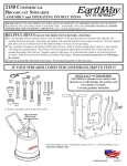
9049 Tyler Blvd. • Mentor, Ohio 44060
Phone (440) 974-8888 • Fax (440) 974-0165
Toll-Free Fax 800-841-8003
Assembly Instructions
IB100B Heavy-Duty Carbon Steel
Walk Behind Salt Spreader
Check contents of box against the parts list to make sure
all components are included. When ordering replacement or
spare parts refer to the parts list for part numbers.
TOOLS NEEDED FOR ASSEMBLY
• (2) 10mm Wrenches
• (2) 1/2 in Wrenches
Attaching the Handle, Linkage Plate Assembly, and Lower
Linkage – Figures 2 – 6
A. Remove contents from box and place the preassembled
portion of the spreader upright on its wheels
B. Slide the Handle onto the spreader frame & line up the holes
C. Carefully insert the Lower Linkage into the Restrictor Plate
underneath the Hopper as shown. (The Lower Linkage has
two bent ends & the Upper Linkage has one threaded end)
D. Insert the other end of the Lower Linkage into the front
hole on the Linkage Plate Assembly
E. Attach the Linkage Plate Assembly and Handle to the
Frame using two M6x40 bolts as shown. Figure 6 shows the
lower linkage assembled (for reference).
NOTE: The Lower Linkage must be attached to the restrictor and the Linkage Plate Assembly before the Assembly
is attached to the frame. If the Linkage Plate Assembly is
attached to the Frame without the Lower Linkage, the Lower
Linkage will be very difficult to assemble and may cause the
restrictor plate to be broken during assembly
Operation
1. Before filling Hopper, ensure that the Restrictor Plate is
fully closed and the screen is in place.
2. Move and tighten the stop bolt to the desired setting.
3. Begin moving forward with the spreader.
4. Pull the Control Handle back to the stop bolt to open
Restrictor Plate and allow material to flow.
5. Before stopping, push the Control Handle fully forward to
stop flow.
Maintenance
1. The Hopper and Spinner should be completely emptied
and cleaned before storage.
2. The Spreader should be washed and dried before storage.
3. Check that the Restrictor Plate and Linkage move freely.
Clear out any debris between the Restrictor Plate & the Hopper.
4. Check that there is no debris in the Gears & that they
move freely.
5. Check torque of all fasteners on a monthly basis.
Attach Control Handle Assembly, Upper Linkage, & Rear
Deflector – Figure 7 & 8
F. Mount the Control Handle Assembly to the Handle using
two M6x40 bolts as shown.
G. Insert the Upper Linkage into the Control Handle as shown.
H. Thread one Jam Nut so that the Restrictor Plate underneath the Hopper is fully open when the Control Handle is at
"30". Assemble the second jam nut in this position to lock the
linkage in place.
I. Verify that the Restrictor Plate may be fully closed by
pushing the Control Handle forward.
J. Using two M6x20 bolts, attach the rear deflector.
Final Assembly
A. Check And Tighten All Fasteners – Make sure the Pinion
and Gear mesh well and turn freely when pushing and pulling the unit.
B. Place the Screen in the hopper.
C. Install the Rain Cover on the hopper.
Operation Notes:
1. The spreader is designed to be operated at a brisk walking
pace (approx. 3mph). Walking slower or faster will alter the
distribution pattern & amount of the material, as will the moisture content of the material & other environmental factors.
2. Grease may be applied to the Pinion & Large Drive Gear
as desired.
WARNING
When filling hopper, make certain there are no large objects within
the material. Objects larger than the openings in the Screen may
cause the spreader to clog or even damage the drive system. Never
leave material in the hopper when not in use.
1
Figure 1 - Contents of Box
Control Handle
Assembly
Figure 2
Linkage Plate Assembly
Screen
Handle Assembly
Upper
Linkage
Step B: Slide
Handle Onto Frame
And Line Up Holes
Preassembled
Spreader
Lower Linkage
Rain Cover And Hardware Kit Are Not Shown
Figure 3
Figure 4
Step C:
Insert Lower Linkage Into Restrictor
Plate. This End To Be Installed
Down Into Control Plate And Then
Rotated To This Position
Hopper Assembly Not
Shown for Clarity
Step D:
Place Control Plate
Assembly Over End of
Lower Linkage as
Shown in Inset
2
opposite view,
assembled
Figure 5
Figure 6
Step E
Attach Control Plate Assembly
To Frame Using M6x40 Bolts
Rod To Be Flat (Parallel
With Ground)
This End Of Rod To
Be Facing Upward
Figure 7
F. Attach Control Handle
Assembly to Frame Using
M6x40 Bolts
Figure 8
G. Remove Control
Handle from Assembly,
Insert Upper Linkage into
Control Handle, Reattach
Control Handle
I. Set the Restrictor
Plate Fully Open and
the Control Handle to
"30" (as shown)
First Jam Nut
H. Thread First Jam Nut onto
Upper Linkage and Insert Linkage
into Control Plate Assembly
J. Attach Rear Deflector
Using M6x20 Bolts
Secure Linkage with Second Jam Nut and Tighten
3
9049 Tyler Blvd. • Mentor, Ohio 44060
Phone (440) 974-8888 • Fax (440) 974-0165
Toll-Free Fax 800-841-8003
20
14
9
16
18
10
15
19
11
21
12
2
15
3
13
Parts List (for all figures)
ITEM
IB100B
QTY
4
DESCRIPTION
13021435
1
Frame
23010874
1
Handle
3 3013399
1
Hopper Assembly
-3008732 Hopper
- 3012702 Restrictor Plate Assembly
4 3015355
1
Spinner Shaft Assembly
5 3012696
1
Spinner Disc
63012692
1
Bushing
7 3008142
1
Deflector Assembly
8 3011734
1
Rear Deflector Assembly
9 3009160
1
Control Handle Assembly
10 3010878
1
Linkage Plate Assembly
11 3010880
1
Upper Linkage
12 3010879
1
Lower Linkage
133014857
2
Wheel
143021432
1
Axle
15 3012680
1
Drive Gear
16 3010871
2
Hopper Support Bracket
173008813
1
Screen
18 3012695
1
Spinner Shaft Support
19 3012704
2
Axle Bushing
203024674
3
E-Clip
21 3007873
1
Agitator Pin
- 3015357
1
Hardware Bag
- 3007993
1
Rain Cover
1
5
6
7
8
FULL ONE YEAR Warranty
Manufacturer will repair, or at manufacturer’s discretion will replace
any part of this salt spreader which proves to be defective in workmanship or material under normal use for a period of one year from
the date of delivery to the original purchaser. Any cost incurred
in returning the product to the supplier is the responsibility of the
consumer.
Exclusions
Manufacturer shall not be liable for special, incidental, or consequential damages, or for damages resulting from lack of necessary maintenance, from misuse, abuse, acts of God, or alteration of the product.
Some states do not allow the exclusion or limitation of incidental or
consequential damages, so the above limitation or exclusion may not
apply to you.
4
3024702 Rev A