1
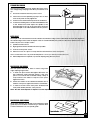
SETUP & OPERATION MANUAL FEATURES Extra large, heavy cast-iron table with a smooth, ground surface finish. 3/4” WOOD SPINDLE SHAPER Two (2) spindle speeds, with reverse. Aluminum Independent left and right fences feature precision micro-adjustment. Two (2) spindles included: 1/2" (Item #40215) & 3/4" (Item #40-220). T-slot miter gauge for better workpiece control. Industrial motor protected against dust by a totally enclosed cabinet. Fence system / cutter head guard includes a cutter guard, spring hold-downs and a built-in 4” dust collection outlet. 1/4” & 1/2” router bit adapters included. Magnetic 2-step safety switch to prevent unwanted or unintentional start-up is equipped with an extra-large easy access stop panel and a lock-out key to prevent unauthorized use of the machine. SPECIFICATIONS TABLE SIZE 27” x 25” (686 x 635 mm) TABLE HEIGHT 34” (864 mm) SPINDLE OPENING DIAMETERS 7”, 3 1/2” & 3” (177, 89 & 76 mm) SPINDLES DIAMETERS 1/2” & 3/4” (13 & 19 mm) SPINDLE TRAVEL 3” (76 mm) SPINDLE SPEEDS 8000 & 10 000 RPM FENCE SIZES (ALUMINUM) 3” x 11”(76 x 279 mm) DUST CHUTE OUTLET 4” (102 mm) OVERALL DIMENSIONS (L X W X H) 21 1/4” x 17 1/4” x 42 1/2” (540 x 438 X 1080 mm) MOTOR 3 HP, 220 V, 1 PH MODEL #40-250 M1 WEIGHT NET: 326 LBS (148 kg) SHIPPING: 343 LBS (156 kg) VERSION 2_RE0VISION 1 - December 14/11 © Copyright General® International 12/2011 GENERAL® INTERNATIONAL 8360 Champ-d’Eau, Montreal (Quebec) Canada H1P 1Y3 Telephone (514) 326-1161 • Fax (514) 326-5555 • www.general.ca THANK YOU for choosing this General® International model 40-250 M1 3/4" spindle shaper. This shaper has been carefully tested and inspected before shipment and if properly used and maintained, will provide you with years of reliable service. For your safety, as well as to ensure optimum performance and trouble-free operation, and to get the most from your investment, please take the time to read this manual before assembling, installing and operating the unit. The manual’s purpose is to familiarize you with the safe operation, basic function, and features of this shaper as well as the set-up, maintenance and identification of its parts and components. This manual is not intended as a substitute for formal woodworking instruction, nor to offer the user instruction in the craft of woodworking. If you are not sure about the safety of performing a certain operation or procedure, do not proceed until you can confirm, from knowledgeable and qualified sources, that it is safe to do so. Once you’ve read through these instructions, keep this manual handy for future reference. Disclaimer: The information and specifications in this manual pertain to the unit as it was supplied from the factory at the time of printing. Because we are committed to making constant improvements, General® International reserves the right to make changes to components, parts or features of this unit as deemed necessary, without prior notice and without obligation to install any such changes on previously delivered units. Reasonable care is taken at the factory to ensure that the specifications and information in this manual corres- ponds with that of the unit with which it was supplied. However, special orders and “after factory” modifications may render some or all information in this manual inapplicable to your machine. Further, as several generations of this model of shaper and several versions of this manual may be in circulation, if you own an earlier or later version of this unit, this manual may not depict your machine exactly. If you have any doubts or questions contact your retailer or our support line with the model and serial number of your unit for clarification. GENERAL® & GENERAL® INTERNATIONAL WARRANTY All component parts of General®, General® International and Excalibur by General International ® products are carefully inspected during all stages of production and each unit is thoroughly inspected upon completion of assembly. Limited Lifetime Warranty Because of our commitment to quality and customer satisfaction, General® and General® International agree to repair or replace any part or component which upon examination, proves to be defective in either workmanship or material to the original purchaser for the life of the tool. However, the Limited Lifetime Warranty does not cover any product used for professional or commercial production purposes nor for industrial or educational applications. Such cases are covered by our Standard 2-year Limited Warranty only. The Limited Lifetime Warranty is also subject to the “Conditions and Exceptions” as listed below. Standard 2-Year Limited Warranty All products not covered by our lifetime warranty including products used in commercial, industrial and educational applications are warranted for a period of 2 years (24 months) from the date of purchase. General® and General® International agree to repair or replace any part or component which upon examination, proves to be defective in either workmanship or material to the original purchaser during this 2-year warranty period, subject to the “conditions and exceptions” as listed below. To file a Claim To file a claim under our Standard 2-year Limited Warranty or under our Limited Lifetime Warranty, all defective parts, components or machinery must be returned freight or postage prepaid to General® International, or to a nearby distributor, repair center or other location designated by General® International. For further details call our service department at 1-888949-1161 or your local distributor for assistance when filing your claim. Along with the return of the product being claimed for warranty, a copy of the original proof of purchase and a “letter of claim” must be included (a warranty claim form can also be used and can be obtained, upon request, from General® International or an authorized distributor) clearly stating the model and serial number of the unit (if applicable) and including an explanation of the complaint or presumed defect in material or workmanship. CONDITIONS AND EXCEPTIONS: This coverage is extended to the original purchaser only. Prior warranty registration is not required but documented proof of purchase i.e. a copy of original sales invoice or receipt showing the date and location of the purchase as well as the purchase price paid, must be provided at the time of claim. Warranty does not include failures, breakage or defects deemed after inspection by General® or General® International to have been directly or indirectly caused by or resulting from; improper use, or lack of or improper maintenance, misuse or abuse, negligence, accidents, damage in handling or transport, or normal wear and tear of any generally considered consumable parts or components. Repairs made without the written consent of General® Internationallwill void all warranty. TABLE OF CONTENTS Rules for safe operation . . . . . . . . . . . . . . .5 Electrical requirements . . . . . . . . . . . . . . .6 Grounding instructions . . . . . . . . . . . . . . . . . . . . . . .6 Circuit capacity . . . . . . . . . . . . . . . . . . . . . . . . . . . . .6 Extension cords . . . . . . . . . . . . . . . . . . . . . . . . . . . . .6 Identification of main parts and components . . . . . . . . . . . . . . . . . . . .7 Unpacking . . . . . . . . . . . . . . . . . . . . . . . . .8 List of contents . . . . . . . . . . . . . . . . . . . . . . . . . . . . . .8 Placement within the shop / Establishing a safety zone . . . . . . . . . . . . .9 Clean up . . . . . . . . . . . . . . . . . . . . . . . . . .9 Assembly instructions . . . . . . . . . . . . . . .10 Basic adjustments & controls . . . . . . . .11-12 Connecting to a power source . . . . . . . . . . . . . . .11 On/off magnetic power switch . . . . . . . . . . . . . . .11 Forward/reverse switch . . . . . . . . . . . . . . . . . . . . . .11 Speed change and belt adjustment . . . . . . . . . .11 Spindle raising and lowering . . . . . . . . . . . . . . . . .12 Changing spindles . . . . . . . . . . . . . . . . . . . . . . . . .12 Operation instructions . . . . . . . . . . . . .12-13 Changing cutters . . . . . . . . . . . . . . . . . . . . . . . . . . .12 Table insert . . . . . . . . . . . . . . . . . . . . . . . . . . . . . . . .12 Operating controls for the fence . . . . . . . . . . . . . .13 Workpiece hold down adjustment . . . . . . . . . . . .13 Protection guard adjustment . . . . . . . . . . . . . . . . .13 Fence adjustment . . . . . . . . . . . . . . . . . . . . . . . . . .13 Tool changing . . . . . . . . . . . . . . . . . . . . . . . . . . . . .14 Before operating . . . . . . . . . . . . . . . . . . . . . . . . . . .14 Cutter rotation . . . . . . . . . . . . . . . . . . . . . . . . . . . . .14 Grain direction . . . . . . . . . . . . . . . . . . . . . . . . . . . . .14 Straight edge shaping . . . . . . . . . . . . . . . . . . . . . .15 Depth of cut . . . . . . . . . . . . . . . . . . . . . . . . . . . . . . .15 Edge shaping: long boards . . . . . . . . . . . . . . . . . .15 Edge shaping: short boards . . . . . . . . . . . . . . . . .15 End shaping . . . . . . . . . . . . . . . . . . . . . . . . . . . . . . .16 Shaping sides . . . . . . . . . . . . . . . . . . . . . . . . . . . . . .16 Shaping contoured edges with rub collar . . . . .16 Enclosed edge shaping . . . . . . . . . . . . . . . . . . . . .17 Templates . . . . . . . . . . . . . . . . . . . . . . . . . . . . . . . . .17 Multi-pieces templates . . . . . . . . . . . . . . . . . . . . . .17 Securing a template to the workpiece . . . . . . . .18 Horizontal toggle clamp . . . . . . . . . . . . . . . . . . . . .18 Protection . . . . . . . . . . . . . . . . . . . . . . . . . . . . . . . . .18 Special cuts . . . . . . . . . . . . . . . . . . . . . . . . . . . . . . .18 Stacked cutters . . . . . . . . . . . . . . . . . . . . . . . . . . . . .19 Butt joints . . . . . . . . . . . . . . . . . . . . . . . . . . . . . . . . . .19 Tenoning . . . . . . . . . . . . . . . . . . . . . . . . .20 Parts list & diagrams . . . . . . . . . . . . . .21-23 RULES FOR SAFE OPERATION To help ensure safe operation, please take a moment to learn the machine’s applications and limitations, as well as potential hazards. General® International disclaims any real or implied warranty and holds itself harmless for any injury that may result from improper use of its equipment. 1. Do not operate the shaper when tired, distracted, or under the effects of drugs, alcohol or any medication that impairs reflexes or alertness. 12. Make sure the cutting tool is running at full operating speed before feeding the work piece. 2. The working area should be well lit, clean and free of debris. 13. Always use clean, properly sharpened cutters. Dirty, dull, bent, cracked or otherwise damaged cutters or bits are unsafe and can lead to accidents. 3. Keep children and visitors at a safe distance when the shaper is in operation; do not permit them to operate the shaper. 14. Feed the stock into the cutter or bit against the rotation direction of the cutter or bit. Never run the stock between the fence and the cutter. 4. Childproof and tamper proof your shop and all machinery with locks, master electrical switches and switch keys, to prevent unauthorized or unsupervised use. 15. Keep guards in place and in working order. If a guard must be removed for maintenance or cleaning be sure it is properly re-attached before using the tool again. 5. Stay alert! Give your work your undivided attention. Even a momentary distraction can lead to serious injury. 16. Never leave the machine unattended while it is running or with the power on. 6. Fine particulate dust is a carcinogen that can be hazardous to health. Work in a well-ventilated area and whenever possible use a dust collector. Wear face, eye, ear, respiratory and body protection devices. 7. Do not wear loose clothing, gloves, bracelets, necklaces or other jewelry while the molder is in operation. Wear protective hair covering to contain long hair and wear non-slip footwear. 17. Use of parts and accessories NOT recommended by GENERAL INTERNATIONAL may result in equipment malfunction or risk of injury. 18. Never stand on machinery. Serious injury could result if the tool is tipped over or if the cutting tool is unintentionally contacted. 19. Always disconnect the tool from the power source before servicing or changing accessories such as cutters, or before performing any maintenance or cleaning, or if the machine will be left unattended. 8. Be sure that adjusting wrenches, tools, drinks and other clutter are removed from the machine and/or the table surface before operating. 20. Make sure that the switch is in the “OFF” position before plugging in the power cord. 9. Keep hands well away from knives and all moving parts. Use a brush, not hands, to clear away chips and dust. 21. Make sure the tool is properly grounded. If equipped with a 3-prong plug it should be used with a three-pole receptacle. Never remove the third prong. 10. Use recommended speed, cutters or bits, accessories and work piece material. 22. Do not use this shaper for other than its intended use. If used for other purposes, GENERAL INTERNATIONAL disclaims any real implied warranty and holds itself harmless for any injury, which may result from that use. 11. Be sure the cutters are securely locked in the cutterhead before starting the machine. 5 ELECTRICAL REQUIREMENTS BEFORE CONNECTING THE MACHINE TO THE POWER SOURCE, VERIFY THAT THE VOLTAGE OF YOUR POWER SUPPLY CORRESPONDS WITH THE VOLTAGE SPECIFIED ON THE MOTOR I.D. NAMEPLATE. A POWER SOURCE WITH GREATER VOLTAGE THAN NEEDED CAN RESULT IN SERIOUS INJURY TO THE USER AS WELL AS DAMAGE TO THE MACHINE. IF IN DOUBT, CONTACT A QUALIFIED ELECTRICIAN BEFORE CONNECTING TO THE POWER SOURCE. THIS TOOL IS FOR INDOOR USE ONLY. DO NOT EXPOSE TO RAIN OR USE IN WET OR DAMP LOCATIONS. EXTENSION CORDS C A B GROUNDING INSTRUCTIONS In the event of an electrical malfunction or short circuit, grounding reduces the risk of electric shock to the operator. The motor of this machine is wired for 220V single phase operation and is equipped with a 3-conductor cord A and a 3-prong grounded plug B to fit a matching grounding type receptacle C. DO NOT MODIFY THE PLUG PROVIDED ! If it will not fit your recepta- cle, have the proper receptacle installed by a qualified electrician. CHECK with a qualified electrician or service person if you do not completely understand these grounding instructions, or if you are not sure the tool is properly grounded. CIRCUIT CAPACITY Make sure that the wires in your circuit are capable of handling the amperage draw from your machine, as well as any other machines that could be operating on the same circuit. If you are unsure, consult a qualified electrician. If the circuit breaker trips or the fuse blows regularly, your machine may be operating on a circuit that is close to its amperage draw capacity. However, if an unusual amperage draw does not exist and a power failure still occurs, contact a qualified technician or our service department. 6 The use of an extension cord is not generally recommended for 220V equipment. If you find it necessary, use only 3-wire extension cords that have 3-prong grounding plug and a matching 3-pole receptacle that accepts the tool’s plug. Repair or replace a damaged extension cord or plug immediately. If you find it necessary to use an extension cord with your machine make sure the cord rating is suitable for the amperage listed on the motor I.D. plate. An undersized cord will cause a drop in line voltage resulting in loss of power and overheating. The accompanying chart shows the correct size extension cord to be used based on cord length and motor I.D. plate amp rating. If in doubt, use the next heavier gauge. The smaller the number, the heavier the gauge. TABLE - MINIMUM GAUGE FOR CORD AMPERE RATING <5 6 TO 10 10 TO 12 12 TO 16 TOTAL LENGTH OF CORD IN FEET 220 VOLTS 25 FEET -------> -------> -------> -------> 50 FEET 100 FEET 150 FEET 18 AWG 16 16 14 18 16 14 12 16 16 14 12 14 12 * NR * NR * NR = Not Recommended 3/4" spindle shaper 40-250 M1 IDENTIFICATION OF MAIN PARTS AND COMPONENTS B C A D K J I E F G H ABCD- WORKPIECE HOLD DOWN GUARD GUARD LOCK KNOB GUIDE FENCE EFGH- FORWARD/REVERSE SWITCH MOTOR ACCESS DOOR MAGNETIC SAFETY SWITCH CABINET I- SPINDLE HEIGHT HANDWHEEL J- TABLE EXTENSION K- MAIN TABLE 7 UNPACKING Carefully unpack and remove the shaper and its components from the box and check for damaged or missing items as per the list of contents below. NOTE: Please report any damaged or missing items to your General International distributor immediately. A B C D E J H F I G K P N O Q R M S L T HEAD LIST OF CONTENTS. . . . . . . . . . . . . . . . . . . . . . . . . . . . . . . . . . . . . . . . . . QTY ABCDEFGHIJKLM- SAFETY GUARD. . . . . . . . . . . . . . . . . . . . . . . . . . . . . . 1 GUARD . . . . . . . . . . . . . . . . . . . . . . . . . . . . . . . . . . . . 1 PLATE GUARD . . . . . . . . . . . . . . . . . . . . . . . . . . . . . . . 1 TENSION SPRING PLATE . . . . . . . . . . . . . . . . . . . . . . . 4 FENCE. . . . . . . . . . . . . . . . . . . . . . . . . . . . . . . . . . . . . 2 GUARD LOCK LEVER . . . . . . . . . . . . . . . . . . . . . . . . . 2 FENCE LOCK LEVER . . . . . . . . . . . . . . . . . . . . . . . . . . 2 FENCE RETAINER . . . . . . . . . . . . . . . . . . . . . . . . . . . . 2 TABLE SLOT RETAINER. . . . . . . . . . . . . . . . . . . . . . . . . 2 PUSH STICK . . . . . . . . . . . . . . . . . . . . . . . . . . . . . . . . . 2 WASHER . . . . . . . . . . . . . . . . . . . . . . . . . . . . . . . . . . . 2 MITER GAUGE . . . . . . . . . . . . . . . . . . . . . . . . . . . . . . 1 BAR . . . . . . . . . . . . . . . . . . . . . . . . . . . . . . . . . . . . . . . 2 TABLE & CABINET ALREADY MOUNTED 8 U V W x y LIST OF CONTENTS. . . . . . . . . . . . . . . . . . . . . . . . . . . . . . . . . . . . . . . . . . QTY NOPQRSTUVWXY- KNOB . . . . . . . . . . . . . . . . . . . . . . . . . . . . . . . . . . . . . 2 ROUTER ADAPTER (1/2” & 1/4) . . . . . . . . . . . . . . . . . 2 SPINDLE 1/2” . . . . . . . . . . . . . . . . . . . . . . . . . . . . . . . 1 SPINDLE 3/4” . . . . . . . . . . . . . . . . . . . . . . . . . . . . . . . 1 WASHER . . . . . . . . . . . . . . . . . . . . . . . . . . . . . . . . . . . 2 PIN . . . . . . . . . . . . . . . . . . . . . . . . . . . . . . . . . . . . . . . 1 DRAW BAR . . . . . . . . . . . . . . . . . . . . . . . . . . . . . . . . . 1 HANDLE . . . . . . . . . . . . . . . . . . . . . . . . . . . . . . . . . . . 1 ALLEN KEY 3 MM . . . . . . . . . . . . . . . . . . . . . . . . . . . . 1 ALLEN KEY 4 MM . . . . . . . . . . . . . . . . . . . . . . . . . . . . 1 WRENCH 12/14 MM . . . . . . . . . . . . . . . . . . . . . . . . . 1 MULTIPLE WRENCH. . . . . . . . . . . . . . . . . . . . . . . . . . . 1 PLACEMENT WITHIN THE SHOP / ESTABLISHING A SAFETY ZONE THIS MODEL 40-250 M1 3/4” SPINDLE SHAPER IS HEAVY. DO NOT OVER-EXERT. THE HELP OF AT LEAST ONE ASSISTANT OR A HOIST WILL BE NEEDED FOR THE FOLLOWING STEP. TO LIMIT THE RISK OF SERIOUS INJURY OR DAMAGE TO THE MACHINE, ANY EQUIPMENT USED TO LIFT THIS MACHINE SHOULD HAVE A RATED CAPACITY IN EXCESS OF 326 LBS (148 KG). PLACEMENT WITHIN THE SHOP This machine should be installed and operated only on a solid, flat and stable floor that is able to support the weight of the molder and the operator. Using the dimensions shown as a guideline, plan for placement within your shop that will allow the operator to work unencumbered and unobstructed by foot traffic (either passing shop visitors or other shop workers) or other tools or machinery. 42 ½ ” ESTABLISHING A SAFETY ZONE For shops with frequent visitors or multiple operators, it is advisable to establish a safety zone around shop machinery. A clearly defined “no-go” zone on the floor around each machine can help avoid accidents that could 21 ¼ ” 17¼” cause injury to either the operator or the shop vi-sitor. It is advisable to take a few moments to either paint (using non-slip paint) or using tape, define on the floor the limits or perimeter of each machines safety zone. Take steps to ensure that all operators and shop visitors are aware that these areas are off limits whenever a machine is running for everyone but the individual operating the unit. CLEAN UP The protective coating on the table, prevents rust from forming during shipping and storage. Remove it by rubbing with a rag dipped in kerosene, mineral spirits or paint thinner. Important: Dispose of potentially flammable solvent-soaked rags according to manfacturer’s safety recommendations. A putty knife, held flat to avoid scratching the surface, may also be used to scrape off the coating followed by clean-up with solvent. Note: Avoid rubbing the molder’s painted surfaces, as many solvent-based products will remove paint. Tip: To prevent rust, apply a light coating of paste wax or use regular applications of any after-market surface protectant or rust inhibitor. 9 ASSEMBLY INSTRUCTIONS For your convenience this shaper is shipped from the factory partially assembled and requires only minimal assembly and set up before being put into service. B A C Place the guard on the table and tightened by two lock lever screws, A. D E Place the plate guard on top of guard and tightened by two knobs, D. Install the safety guard to front of plate guard and tightened by two knobs, E. in proper position. G Install two bars to the retainer and use the tension spring plate to go through the retainer and tightened by knob, G. 10 Apart the lock lever, B, and T screw from the hardware bag, and assemble these two parts to go through the hole on the bracket, screw it clockwise and leave some space, then slide the fence, C, through the T screw till to proper position and tightened by lock lever. F Place two bars on the hole of bracket and tightened by hex screw, F . H I Insert the T screw on retainer, H, to go through the table t-slot and move to proper position and tightened by knob. Insert the tension spring plate to go through the retainer and tighten the bolt, I. BASIC ADJUSTMENTS & CONTROLS CONNECTING TO A POWER SOURCE Once the assembly steps have been completed, plug the power cord into an appropriate outlet. Refer back to the section entitled “ELECTRICAL REQUIREMENTS” and make sure all requirements and grounding instructions are followed. When cutting operations have been completed unplug the saw from the power source. SWITCH OFF TO AVOID UNEXPECTED OR UNINTENTIONAL START-UP, MAKE SURE THAT THE POWER SWITCH ON THE SAW IS IN THE OFF POSITION BEFORE CONNECTING TO A POWER SOURCE. STOP TO AVOID RISK OF SHOCK OR FIRE DO NOT OPERATE THE UNIT WITH A DAMAGED POWER CORD OR PLUG. REPLACE DAMAGED CORD OR PLUG IMMEDIATELY. ON/OFF MAGNETIC POWER SWITCH This model 40-250 M1 is equipped with a Magnetic 2step safety switch to prevent unwanted or unintentional start-up and unauthorized use of the saw. F O R W A R D / R E V ER S E S WIT C H A The switch assembly is equipped with a GREEN “START” button A, an extra-large easy access RED stop panel B, and a lock-out key C. B To start the shaper: Insert the lock-out key C and press on the GREEN “START” button A. C To stop the shaper: Press on the RED “STOP” panel, B. Once the RED “STOP” panel has been pressed, the saw can only be started by pressing once again on the RED “STOP” panel to release the green button, then by pressing on the green button. FORWARD/REVERSE SWITCH When reverse rotation needs to be used; power must be switched OFF" and press the reverse button. TO PREVENT UNWANTED OR UNAUTHORIZED START-UP OR USAGE, REMOVE THE LOCK-OUT KEY AND STORE IT IN A SAFE PLACE, OUT OF THE REACH OF CHILDREN, WHENEVER THE SAW IS NOT IN USE. SPEED CHANGE AND BELT ADJUSTMENT The 40-250 Shaper has been designed with 2 speed pulley 8000 RPM & 10000 RPM. Follow these procedures to change speed and adjust the proper belt tension. 1. Disconnect machine from power source. 2. Open the base door. 3. Turn lock handle, A, counter clockwise to release belt tension. 4. Move the belt to the other groove, B. 5. Push handle bar, C, to get proper belt tension. 6. Tighten the lock handle, A. 7. Close door. A B C 11 SPINDLE RAISING AND LOWERING B Adjust the main shaft to the up or down position. 1. Loosen the front hand wheel, A. 2. Turn the Hand wheel, B, to the desired height. 3. Tighten the hand wheel, A. SPINDLE ASSEMBLY CHANGING SPINDLES A 3/4" and 1/2” spindle assemblies are supplied with your shaper. The assemblies are locked in a tapered seat with a draw bar and nut. To change spindles One wrench must be placed on the flats on top of the spindle and the second wrench on the draw bar nut, this allows the spindle to loosen. Turn the nut two times; tap gently upwards with a wooden block, this will loosen the spindle from the taper. Remove nut and lift out the spindle. FLAT AT TOP OF SPINDLE DRAW BAR NUT OPERATION INSTRUCTIONS CHANGING CUTTERS All spindle sizes are equipped with a safety lock nut, lefthand threads are found above the large spindle nut. To mount or change cutter, first remove the safety lock nut: Remove the spindle nut by placing one wrench on the spindle nut and another wrench on the flats on top of the spindle. Safety lock nut must be replaced before starting work operations. AVAILABLE: Item #40-225: 1” optional arbor Item #40-230: 1 1/4” optional arbor TABLE INSERT 40-250 spindle shaper has been designed with three spindle inserts. The 3 table inserts have an opening of 7" (178 mm), 3 1/2" (89 mm) and 3" (76 mm). 12 SPINDLE SAFETY LOCK NUT SPINDLE NUT SPACER OPERATING CONTROLS FOR THE FENCE Depending on the type of work you are shaping, either side of the fence can be moved freely. Fence can be moved by loosening wing screws, A, proper setting can be achieved by turning knob, B. The turning knob, B, is with scale for accurate setting. Wing screws, A, must be then tightened to fix in position. A C Each fence half should be adjusted as close to cutter head as possible. To position fence closer to cutter head, loosen handle, C. Fence plate, D, must be moved to correct position. Then tighten the handle, C. WORKPIECE HOLD DOWN ADJUSTMENT B D PROTECTION GUARD ADJUSTMENT A Loosen knob, A, turn tension plate to desired angle, then tighten the bolt. B Loosen two knobs to slide protector, B, to desired height. FENCE ADJUSTMENT The fence is fixed the position before shipment, following the instruction for when need to do the minor fence adjustment. D E 1. Loosen the screw, A, and turn set screw, B, for adjust the fence to proper position then tighten screw, A. (Improper position, F) C 2. Loosen the screw, A, and turn set screw, D, set screw for adjusting the fence to proper position then tighten screw, A. (Improper position, G) Bracket G F B Fence H Fence I Fence 4. Loosen the screw, A, and adjust set screw, C, for adjusting the fence to proper position then tighten screw, A. (Improper position, I) Fence 3. Loosen the screw, A, and adjust set screw, E, for adjusting the fence to proper position then tighten screw, A. (Improper position, H) A Bracket Bracket Bracket 13 TOOL CHANGING When changing tools, the process demands lots of attention and extra precautions, keep in mind the following procedures. 1. Spacers, cutters and collars mounted on the spindle shaft must be in a fixed position. There must be no move ment, space or touching between parts. 2. Counter bores and holes of collars, cutters or spacers must be in perfect condition with no rust or flaws. 3. Before installing the collars, cutters and spacers on the spindle they must be cleaned properly. 4. The cutter must always be mounted as low as possible on the spindle. 5. Always check before starting the shaper that all parts on the spindle are locked in position. BEFORE OPERATING The main drive motor should run for a few seconds, to make sure that it is performing in the proper rotation. Looking down at the spindle, it should be rotating counter-clockwise this is the proper position. Machine should stay on for a short period of time to make sure that all moving parts are properly positioned with no excessive vibration. If any adjustments are required disconnect machine from the power source before properly adjusting. ALL WORK OPERATORS MUST READ AND UNDERSTAND THE MANUAL BEFORE STARTING ANY WORK OPERATIONS ON THE SHAPER ! ALL SHAPER OPERATIONS MUST BE USED WITH THE PROPER GUARDS, AND ANY OTHER SAFETY REQUIREMENTS TO INSURE SAFETY OF THE OPERATOR! CUTTER ROTATION COUNTER CLOCKWISE SETUP Cutter must be positioned as work piece must be fed from right to left. CLOCKWISE SETUP Cutter must be positioned as work piece must be fed from left to right. GRAIN DIRECTION The work piece should always be shaped in the same direction as the grain (if possible). When cut against the wood grain, woods as redwood, fir and oak will leave a rough, or slightly splintered edge. WHEN DEEP CUTS ARE REQUIRED, THEY WILL NEED STRONG POWER AND A PUSHING FORCE IN ORDER TO CONTROL THE CUT. DEEP CUTS CAN ALSO CAUSE THE WOOD TO SPLIT OR SPLINTER, THIS MAY LEAD TO LOSS OF CONTROL OR INJURES TO THE WORK OPERATOR. WHEN A FINISHED EDGE IS NOT TO YOUR SATISFACTION, CUT A FEW MORE TIMES WITH NO MORE THAN 1/16" DEEP. PRE-CUT STOCK ON BAND SAW 1/16" WHENEVER POSSIBLE. THE TRAILING BOARD EDGE WILL SPLINTER WHEN SHAPING ACROSS THE GRAIN. THE BEST SOLUTION WOULD BE TO CUT THE BOARD 1 /4" OVERSIZE IN WIDTH SHAPE THE BOARD AND SIMPLY TRIM OFF THE EXCESS. 14 STRAIGHT EDGE SHAPING The work piece must always be against the fence to perform straight edge shaping, follow these procedures to set up: 1. Disconnect machine from the power source. 2. Fence faces must be parallel, properly in line or offset If necessary, and securely tightened. 3. Cutter must be rotated and inspected for clearance. 90° 4. Position the leading face of a cutter head blade at 90° to the infeed fence and adjust the spindle to the desired height of the cut. At the same time check the desired depth of cut with the blade in the 90° position. DEPTH OF CUT The depth of cut is the distance from the outside circumference edge of the collar which the work rides against to the outside edge of the cutter. The depth of the cut is determined by the position of the fence relative to the cutter head or by the use of shaper collars. 1. Spindle must be locked. 2. Right guard should be installed wherever possible. 3. Connect to the power source. 4. Make a test cut on a piece of scrap with the same thickness as the work piece. Note: To determine if the cut, profile and depth are correct you will only need a short cut. 5. Make adjustments if required, or proceed shaping using the work piece. EDGE SHAPING: LONG BOARDS The work piece must be at least 12 inches long when edge shaping long boards. 1. To hold work piece down and against the fence use the hold-downs and horizontal clamps. If the work piece is too wide for the horizontal clamps, clamp a scrap board to the table to keep the work piece against the fence. 2. Check the rotation of the cutterhead, and be sure to feed the work piece against the ration of cutterhead. 3. To make a smooth cut the work piece should be fed slowly and steadily with firm, even pressure. Note: The rate feed depends on depth of cut and experience of operator. EDGE SHAPING: SHORT BOARDS STOCK When edge shaping short boards, never attempt to hand guide any stock less than 12 inches long, or narrower than 3 inches without the use of a special guide. Special Guide 15 END SHAPING Scrap When end shaping narrow stock at least one half of the work piece end must be in contact with either the outfeed or infeed fence. NEVER ATTEMPT TO SHAPE A NARROW PIECE WITHOUT A SPECIAL GUIDE, THE WORK PIECE MAY STAR ROCKING INTO THE CUTTER HEAD CAUSING MINOR OR MAJOR INJURY TO THE WORK OPERATOR. SHAPING SIDES Workpiece ON-EDGE SHAPING 4th CUT 1st CUT 2st CUT Wide stock 3rd CUT When shaping across the grain, some woods are more likely to chip out or splinter. It is recommended to shape cross grain sides first. Any chipping that does occur will be removed by the subsequent cut with the grain. High fence Using the existing bolts in the fence, attach a taller shop-made fence when the shaper fence does not support firmly support taller stock. Note: To avoid interference with mounting screw, make sure the bolt holes are on your shop-made tall fence are countersunk. SHAPING CONTOURED EDGES WITH RUB COLLARS A To shape contoured edges the fence assembly should be removed. In order to control the work piece and limit the depth of cut an anti-friction collar must be used, A. Cutter The purpose of the collar is to ride against the work piece, at the same time the collar establishes the depth of cut, B. The collar can be positioned above or below the cutters. The ring guard should be used whenever possible. Depth of cut Anti-friction collar Collar C At least 1/8” edge thickness When work piece is not contoured all around, start the cut as shown in D. Small size materials need a special shaping jig, E. Cutter 16 B Cutter Note: The collar requires at least 1/8" of surface edge to ride against, the entire edge cannot be shaped, C. However the use of a pattern or template will permits the shaping of the entire edge. When work piece needs to be shaped alt around the perimeter, hold firmly and press the work straight into the cutter until the collar established depth of cut. While holding firmly, keep feeding the work so the point of contact on the edge is always 90° to the collar. Collar Workpiece D Collar Workpiece edge 90° START POSITION Feed Remove entire fence assembly; place jig carefully at the desired depth of cut, clamp to table securely. It is important with arc and circle shapes that the work piece must be roughly cut to desired size and curve of the finished piece, before being shaped. The curve of the jig must match the work piece exactly. The work piece must be firmly attached to the jig. This operation should always be in use of a ring guard or a similar safety device over the cutter head. NEVER ATTEMPT TO SHAPE FREEHAND. OPERATOR SHOULD NEVER RACE HANDS NEAR THE CUTTERS OR CUTTERHEAD ! KEEP HANDS AT A DISTANCE OF 12" AWAY FROM ANY CUTTING DEVISES. E Feed Use the guard! Clamp ENCLOSED EDGE SHAPING Inside edge work piece are shaped the same way as outside edges. When the whole edge needs to be shaped, the operator must use a pattern. The work piece must be placed on table before starting the motor. The operator must shape the whole work piece by feeding into the cutters. Feed NEVER ATTEMPT TO PERFORM THIS PROCEDURE WITHOUT A RING GUARD OR A SIMILAR SAFETY DEVICE OVER CUTTERHEAD ! OPERATION MUST BE AWARE AT ALL TIMES OF THE FEED DIRECTION ! OPERATION MUST NOT BE LEFT UNATTENDED! Hand hold Guide pin 1. Use a firm grip to ease the edge into the cutters untilstopped by the collar. 2. Keep pushing straight while turning and feeding the work piece, continue until the cut is finished. Turn power switch in the off position and remove the work piece only once the cutters have come to a complete stop. Feed NEVER PERFORM ENCLOSED EDGE SHAPING WHEN THERE IS LESS THAN 12" OF WOOD MATERIAL ALL AROUND THEOPENING ! THE ONLY TIME THIS CAN BE DONE IS IF THE WORK PIECE IS ATTACHED TO A LARGER WOOD BASE! NEVER PERFORM ENCLOSED HAPING WHEN WORK PIECE OPENING IS MALLER THAN TWICE THE DIAMETER IN ANY DIRECTION. TEMPLATES MULTI-PIECED TEMPLATES Template Workpiece A template serves as guide for the cutter. The template must be made of scrap material thick enough to provide a solid bearing edge against a collar, recommended size 3/4". When the work piece requires all-around shaping, the template, may be built from various sections fixed together. 17 SECURING A TEMPLATE TO THE WORK PIECE Various methods are used to secure template to the work piece. The operator should select the best method to secure the template to the work piece based on the size, shape, and constriction of the template and work piece. Handles Handles Workpiece Dowels “C” Clamps "C" clamps can be used to securely hold a template when the work piece is large enough to surpass the front of table, while still leaving space for the desired cut. The work piece may be placed against the template using dowels as anchor points and wooden blocks to help the operator in guiding the work piece through the cut. HORIZONTAL TOGGLE CLAMP Toggle clamp Horizontal toggle clamp are useful when the regular "C" clamps cannot allow the freedom of movement required in shaping. No additional hand pressure is necessary for the operator to control the work piece. Anchor points like dowels are necessary with this setup. Workpiece PROTECTION The operators should take precautions to protect themselves, and all others around the work area and the machine itself for improper use. Never leave machine unattended while it is running, the operator needs to be very focused and attentive, and not looking elsewhere or carrying on conversation while using the machine. Carelessness or inattention will result in serious injuries and damages. SPECIAL CUTS The illustrations in this section show the profile or section views made by the cutters. The most efficient cutters are carbide tipped to ensure cleaner cuts and longer cutter life. Small cutters may be solid carbide, some use inserts. Since there is such various choices, the operator is limited only by his experience and imagination. 18 STOCK Cutter collar STACKED CUTTERS A variety of timesaving and interesting cuts can be made in a single setup by stacking the cutters, A. When stacking cutters extra care should be taken. Check that cutters have no flaw nicks, or just. Cutters must cleaned and perfectly balanced before placing in the stacked poisiton. A Cutter Stock Stock Collar Sash cutter Groove cutter Door shaping requires two operations, demonstrates sash cut for the first operation. When the stock is flipped over and the sash cutter with a 1/4" groove cutter to complete the cut. Collar First shaping cut with the sash cutter for the matching door stile sash. Sash cutter Flip over cut Same cut with the stock flipped over. Rabbet cut Collar Stub spindle Groove cutter First shaping out, for a window sash stile using a sash cutter, collar, and a 1/2" groove cutter. BUTT JOINTS GLUE BUTT JOINT: To perform a glue butt joint, both fences must be kept inline and adjusted for a depth of cut, A. Both cuts on the work pieces are part-edge cuts that do not reduce the width of material during cutting procedures. When shaping the work pieces, one must be ted top-side up, and the other is fed bottom-side up. TONGUED JOINT: similar to the glue joint, both fences are kept in-line for the tongued joint and must be adjusted for 1/4" depth of cut with no reduction in stock width. With this joints, both work pieces are fed with the same side up, B. DROP LEAF JOINT: A drop leaf joint work piece is shaped using a Drop Leaf Bead cutter, the table work piece is shaped with d Drop Leaf Cove cutter. This joint type, the whole edge of both work pieces are shaped the same side up and allows 1/16" reduction in width. Adjust the infeed fence to reduce the work piece width by 1/16" and adjust the outfeed-fence to compensate for stock removed, C. Both cuts needed for a window sash rail end. The first operation at top is a rabbet cut made with a groove cutter. The second operation is performed with a stub spindle and button head screw. A B C 19 TENONING Figure A demonstrates the tenoning fixture which shows a miter gauge equipped with a hold-down for shaping the ends of narrow work piece. A Miter gauge can also be adapted to cut square and centered tenons at the ends of leg for table, chairs etc. Secure leg to the jig and position for cut, B. A First cuts must be made with the same jig setting and spindle height. When the first several cuts have been made, reposition the leg on the jig for each succeeding cut. Miter gauge Note: If legs are tapered. Use a wedge to set the side facing the cutter to 90 degrees vertical, C. B C Clamp Miter gauge NOTE: 20 Leg Wedge Cutter Hold down Taper leg CABINET QUILL 61 67 68 69 63 24 25 25 46 62 40 66 54 42 64 65 59 54 60 45 14 26 46 13 26 27 56 28 79 46 55 54 29 14 15 53 58 57 51 49 15 13 52 25 30 31 32 33 15 13 34 50 41 40 42 . 47 48 46 45 35 42 44 40 25 41 43 37 38 36 39 25 25 21 SPINDLE 111 109 108 112 136 131 110 109 135 133 134 132 113 136 127 111 112 135 130 114 133 101 115 118 116 119 122 114 129 117 120 121 128 116 120 117 123 119 124 118 121 125 103 104 26 125 FENCE 103 126 22 103 26 126 102 PARTS LIST 40-250 PART N0. DESCRIPTION 40250-01 40250-02N 40250-03 40250-03A 40250-04 40250-04A 40250-04B 40250-05 40250-06 40250-07 40250-08 40250-09 40250-10 40250-11 40250-12 40250-12A 40250-13 40250-14 40250-15 40250-16 40250-16A 40250-17N 40250-19 40250-20 40250-21 40250-22 40250-23 40250-24 40250-25 40250-26 40250-27 40250-28 40250-29 40250-30 40250-31 40250-32 40250-33 40250-34 40250-35 40250-36 40250-37 40250-38 40250-39 40250-40 40250-41 40250-42 40250-43 40250-44 40250-45 40250-46 40250-47 40250-48 40250-49 40250-50 40250-51 40250-52 40250-53 40250-54 40250-55 40250-56 40250-57 40250-58 40250-59 40250-60 40250-61 40250-62 40250-63 40250-64 40250-65 STAND ASSEMBLY SWITCH SCREW 5/32" X 1"L SCREW 5/32" X 4"L FORWARD-REVERSE SWITCH FORWARD-REVERSE SWITCH COVER CONNECTOR NUT. HEX 5/32" BAR MITER GAUGE SCREWS SET 5/16" X 5/8" L INSERT TABLE INSERT TABLE INSERT TABLE TABLE EXTENSION WING HEX NUT 3/8" SPRING WASHER 3/8" WASHER 3/8" DUST REMOVABLE DOOR 3/8" X 3/4"L SCREW DOOR LOCK LEVER PIN MOTOR COVER HANDLE LOCK ELECTRIC CORD CONNECTOR SPINDLE BASE HEX NUT 1/2" SCREW 3/8" X 1" SCREW 3/8" X 1-1/4" COLLAR HANDLE KEY SET SCREW 5/16" X 3/8" MOTOR PULLEY KNOB MOTOR BASE MOTOR SCREW 5/16" X 5/8" SPRING SPRING SHAFT WASHER 1/2" SPRING WASHER 1/4" SCREW 1/4" X 3/4" WASHER 1/4" SCREW 1/2" WASHER 5/16" SPRING WASHER 1/4" HEX NUT 5/16" POINTER SCREW 5MM X 10MM V-BELT K-23 SHAFT GUIDE PLATE MOTOR PLATE SCREW 1/2" X 1" SCREW 5/16" X 1" GEAR SHAFT GEAR SHAFT BASE HANDWHEEL KNOB WASHER 5/16" SET SCREW 5/16" X 5/8" HANDWHEEL SCREW 1/4" X 1" LOCK BAR LOCK SCREW GEAR WASHER QTY 1 1 2 2 1 1 4 2 2 3 1 1 1 1 1 1 14 20 17 1 12 1 2 1 1 1 1 1 6 12 1 1 1 1 1 1 1 1 1 4 1 1 1 7 6 7 1 8 9 12 1 1 1 1 1 1 1 4 1 1 1 1 2 1 1 1 1 1 1 PART N0. DESCRIPTION 40250-66 40250-67 40250-68 40250-69 40250-70 40250-71 40250-72 40250-73 40250-74 40250-75 40250-76 40250-77 40250-78 40250-79 40250-80 40250-81 40250-82 40250-83 40250-84 40250-85 40250-86 40250-87 40250-88 40250-89 40250-90 40250-91 40250-92 40250-101 40250-102 40250-103 40250-104 40250-108 40250-109 40250-110 40250-111 40250-112 40250-113 40250-114 40250-115 40250-116 40250-117 40250-118 40250-119 40250-120 40250-121 40250-122 40250-123 40250-124 40250-125 40250-126 40250-127 40250-128 40250-129 40250-130 40250-131 40250-132 40250-133 40250-134 40250-135 40250-136 40250-137 40250-138 40250-139 40250-140 40250-141 40250-142 40250-143 40250-144 40250-145 GEAR COLLAR KEY GEAR SHAFT HEX NUT 5/8" HEX NUT 3/4" COLLAR 3/4" X 1/2" COLLAR 3/4" X 3/4" COLLAR 3/4" X 1" SPINDLE 3/4" SHAFT KEY 5MM BEARING 6205LLB QUILL SPINDLE 1/2" HEX NUT 3/8" HEX NUT 1/2" COLLAR 1/2" X 3/4" COLLAR 1/2" X 1" COLLAR 1/2" X 1" BEARING 6205Z SNAP RING SPINDLE PULLEY LOCK WASHER LOCK NUT LOCK BOLT LOCK NUT BAR TENSION SPRING PLATE RETAINER KNOB UPPER FENCE HOUSING LOCK LEVER CARRIAGE BOLT LOCK LEVER WASHER KNOB KNOB SCREW BOLT FENCE TRAVEL BUSHING LOCK HANDLE WASHER BRACKET T- SCREW FENCE BOLT SET SCREW KNOB SCREW T-HEX NUT 3/8" PLASTIC COVER FENCE HOUSING FRONT GUARD WING SCREW SCREW WASHER BOLT SCALE ADJUSTMENT KNOB SET SCREW PUSH STICK T-BRACKET PIN ROUTER 1/4" ROUTER 1/2" MULTIPLE WRENCH (NOT SHOWN) WRENCH 12/14 MM (NOT SHOWN) ALLEN KEY 3MM (NOT SHOWN) ALLEN KEY 4MM (NOT SHOWN) QTY 1 1 1 1 1 1 1 2 1 1 1 1 1 1 1 1 1 2 2 1 1 1 1 1 1 1 1 2 4 4 2 1 2 2 2 2 1 2 4 2 2 2 2 2 2 2 2 8 2 2 1 1 1 2 4 2 2 2 2 2 2 2 1 1 1 1 1 1 1 23 MODEL 40-250 M1 8360 Champ-d’Eau, Montreal (Quebec) Canada H1P 1Y3 Fax: (514) 326-5565 - Tel.: (514) 326-1161 Fax: (514) 326-5555 - Parts & Service / Order Desk [email protected] www.general.ca IMPORTANT When ordering replacement parts, always give the model number, serial number of the machine and part number. Also a brief description of each item and quantity desired.