1
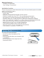
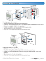
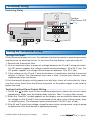
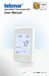
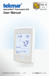
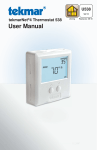
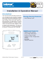
518_D
03/13
Thermostat 518
Zoning
Replaces: New
Installation & Operation Manual
Introduction
The Thermostat 518 accurately controls the
room temperature for a hydronic heating
zone using Pulse Width Modulation (PWM)
technology. Simple up and down buttons
and a display with large type make this
thermostat easy to read and use. The 518
automatically detects a single auxiliary
sensor to measure either outdoor, floor
or remote room temperature. This easy to
install thermostat is a direct replacement
for tekmar Thermostats 507 and 508.
Energy Saving Features
• Auto Heating Cycle
Additional Features
•
•
•
•
Radiant Floor Heating
Pulse Width Modulation
Auxiliary Sensor Input
Outdoor & Floor Temperature
Display
• Backlight
• Freeze Protection
A Watts Water Technologies Company
1 of 12
© 2013
518_D - 03/13
Table of Contents
Getting Started ...............................2
Installation ...........................................2
Preparation .....................................2
Removing The Thermostat Base ....3
Mounting The Thermostat...............4
Thermostat Wiring ..........................5
Testing the Thermostat Wiring ........6
User Interface ......................................7
Home Screen ..................................7
Symbols Description .......................7
Sequence of Operation........................8
Heating Operation...........................8
Programmable Settings .......................9
Troubleshooting .................................10
Error Messages ............................10
Frequently Asked Questions ........ 11
Technical Data .............................. 11
Limited Warranty and Product
Return Procedure .........................12
Getting Started
Congratulations on the purchase of your new tekmar® thermostat.
This manual will step through the complete installation, programming and sequence
of operation for this control. At the back, there are tips for control and system
troubleshooting.
Installation
Caution
Improper installation and operation of this control could result in damage to the
equipment and possibly even personal injury or death. It is your responsibility to
ensure that this control is safely installed according to all applicable codes and standards.
This electronic control is not intended for use as a primary limit control. Other controls
that are intended and certified as safety limits must be placed into the control circuit.
Preparation
Tools Required -------------------------------------------------------------------------------------------• tekmar or jeweller screwdriver
• Wire Stripper
• Phillips head screwdriver
A Watts Water Technologies Company
2 of 12
© 2013
518_D - 03/13
Materials Required -----------------------------------------------------------------------------------• 18 AWG LVT Solid Wire
(Low Voltage Connections)
Installation Location ------------------------------------------------------------------------------Choose the placement of the thermostats early in the construction process to enable
proper wiring during rough-in.
Consider the following:
• Interior Wall.
• Keep dry. Avoid potential leakage onto the control.
• Relative Humidity less than 90%. Non-condensing environment.
• No exposure to extreme temperatures beyond 32-122°F (0-50°C).
• No draft, direct sun, or other cause for inaccurate temperature readings.
• Away from equipment, appliances, or other sources of electrical interference.
• Easy access for wiring, viewing, and adjusting the display screen.
• Approximately 5 feet (1.5 m) off the finished floor.
• The maximum length of wire is 500 feet (150 m).
• Strip wire to 3/8” (10 mm) for all terminal connections.
• Use standard 4 conductor, 18 AWG wire.
Removing The Thermostat Base
To remove the thermostat base:
• Locate the tab on the bottom of the
thermostat.
• Push the tab with either your thumb or with
a screwdriver.
• Lift the thermostat front away from the
thermostat’s base.
A Watts Water Technologies Company
3 of 12
© 2013
518_D - 03/13
Mounting The Thermostat
Stud
Adapter Plate 012
Thermostat
Front
Thermostat
Base
3 1/4”
(83 mm)
Gang
Box
If a single gang box is used:
• Adapter Plate 012 is required (sold separately).
• Feed the wiring through the hole in the adaptor plate and the thermostat base.
• Fasten the adaptor plate to the gang box.
• Fasten the base of the thermostat to the adaptor plate.
• Terminate wiring to the wiring strip.
• Push the thermostat front onto the thermostat base.
Thermostat
Base
Thermostat
Front
Wall
If mounting directly to the wall:
• Drill holes and install the wall anchors.
• Feed the wiring through the large hole in the thermostat base.
• Fasten the thermostat base to the wall using the wood screws to the wall
anchors.
• Terminate wiring to the wiring strip.
• Push the thermostat front onto the thermostat base.
A Watts Water Technologies Company
4 of 12
© 2013
518_D - 03/13
Thermostat Wiring
Zone Valve --------------------------------------------------------------------------------------------Install field
jumper wire
R to Rh
Zone
Valve
RC
518
Optional
Slab Sensor 079
No Power
C
R Rh W1 S1 Com
24 V (ac)
Transformer
009
LN
Wiring Center 315 or 316 -----------------------------------------------------------------------Install field
jumper wire
R to Rh
518
tN4
C
R
Optional
Slab Sensor 079
No Power
C
R Rh W1 S1 Com
W
Wiring Center
315 or 316
Relay 003 -----------------------------------------------------------------------------------------------------Relay 003
3
4
5
6
2
1
8
7
Install field
jumper wire
R to Rh
R C
518
Optional
Slab Sensor 079
No Power
C
R Rh W1 S1 Com
NLG
Transformer
009
115 V (ac)
A Watts Water Technologies Company
5 of 12
© 2013
518_D - 03/13
Thermostat Wiring
Switching Relay -------------------------------------------------------------------------------------------
Optional
Slab Sensor 079
518
R W
Zone 1
R W
Zone 2
C
No Power
R Rh W1 S1 Com
R W
Zone 3
24 V
Com
Class 2
Transformer
Switching Relay
X
X
Zone 1
H N
Zone 2
H N
Zone 3
H N
N
H
NL
Pump
Testing the Thermostat Wiring
Testing the Power -----------------------------------------------------------------------------------If the thermostat display turns on, this indicates that the thermostat is operating correctly
and there are no electrical issues. In the event that the display is permanently off:
1. Remove the thermostat front.
2. Use an electrical meter to measure voltage between the R and C wiring terminals.
For AC power supplies the voltage should measure between 10 to 30 V (ac). For
DC power supplies the voltage should measure between 10 to 30 V (dc).
3. If the voltage on the R and C wire terminations is continuous and the thermostat
display is not on, the thermostat may have a fault. Contact your tekmar sales
representative for assistance.
If the thermostat display intially powers on but later shuts off intermittantly, there
may be a short circuit from the W wire to ground, or the power supply is too small to
power the load.
Testing the Heat Zone Output Wiring -------------------------------------------1. Touch the
button and set the heating temperature above the current room
temperature. Make sure the display does not flash “Max” if using a floor sensor.
2. When the “Heat On” symbol appears on the display, use an electrical meter to check
for voltage on the W and C wires connected to the zone valve, wiring center, relay
or switching relay. The electrical meter should read 10 to 30 V (ac) or (dc).
3. If the W and C wire have voltage, check the zone valve, wiring center, relay or pump
to determine if the heat device is operating correctly.
A Watts Water Technologies Company
6 of 12
© 2013
518_D - 03/13
User Interface
Home Screen
Symbols Description
HEAT ON
Heat is turned on.
MIN
The floor is at or below the
floor minimum temperature.
MODE OFF
The heating system is off.
WARNING SYMBOL
Indicates an error is present.
A Watts Water Technologies Company
7 of 12
MAX
The floor has reached the
floor maximum temperature.
© 2013
518_D - 03/13
Sequence of Operation
Heating Operation
To change the heat temperature setting, push the
or
button to select a preferred
temperature setting. The Heat On symbol is shown on the display when the thermostat is
heating. The heat can cycle on and off within +/- 1.5°F (1°C) of the temperature setting.
The floor and air heating can be shut off by holding the
button until Set Room is Off.
button to navigate to the Mode
To resume heating when the Mode is Off, press the
setting, then press the
button to select Mode Heat. The thermostat will resume
heating at the last previously set temperature.
Air Temperature Only -------------------------------------------------------------------------If there is only an air temperature sensor (no floor sensor), the thermostat operates to
control your desired air temperature.
Floor Temperature Only -----------------------------------------------------------------------If the air sensor has been disabled, the thermostat will only maintain floor temperature
and ignore air temperature. This operation is recommended for areas such as bathrooms
to ensure that tile floors are warm to the touch.
Floor and Air Temperature ----------------------------------------------------------------If the air sensor is turned on and a floor sensor is connected, the thermostat will maintain
the desired air temperature as well as a minimum floor temperature.
This operation is recommended for areas with large windows that allow the sun to
shine into a room and keep it warm without the need for heat. This can allow the floors
to cool off during the afternoon. When the sun goes down, it can take a long time for
the floors to get warm again. This may cause the room to cool off too much in the early
evening. A floor minimum setting can help with this condition by maintaining a floor
minimum temperature. Keep in mind the floor minimum temperature will override the
air temperature, and if set too high, may overheat the room.
This operation is also recommended for rooms with hardwood floors. Setting floor
minimum and maximum temperatures is a way of enhancing the comfort of the living
space while protecting floor coverings.
90°F (32°C)
Feels hot to the touch
Suggested maximum for all floor
types other than wood.
80 to 85°F (26 to 30°C)
Feels warm to the touch
Bathrooms and kitchens. Suggested
maximum for wood floors.
70°F (21°C)
Feels cool to the touch
Rooms with large windows preventing
under heating in the evening.
40 to 45°F (5 to 7°C)
Feels cold to the touch
Freeze protection for garages.
A Watts Water Technologies Company
8 of 12
© 2013
518_D - 03/13
Programmable Settings
Setting
Display
User settings. Press the
and
advance to the next setting.
buttons together for 3 seconds to enter and
MODE
Select heat or off.
Range: HEAT, OFF
Default: HEAT
UNITS
Select the temperature units.
Range: °F or °C
LIGHT
Select when the display back light should operate. Auto
operates the backlight for 30 seconds after a keystroke.
Range: OFF, AUTO, ON
SET FLOOR
Set the floor minimum temperature. Available when an
auxiliary floor sensor is connected and the built-in room
sensor is on.
Range: OFF, 40 to 122°F (4.5 to 50.0°C)
TYPE
button to view the
Device Type number. Hold the
software version.
ESCAPE
Release the
and
Default: °F
Default: AUTO
F
Default: 72°F (22.0°C)
buttons to return to the home screen.
Installer settings. Press the
and
buttons together for 5 more seconds.
AUXILIARY SENSOR
Select the type of auxiliary sensor. Available when an auxiliary
sensor is automatically detected.
Range: NONE = no auxiliary sensor, ROOM = Indoor
Default: OFF
Sensor, FLOR = Slab Sensor, OUT = Outdoor Sensor
ROOM SENSOR
Select if the built-in room temperature sensor is on or off.
The built-in room sensor can only be disabled when an
auxiliary room or slab sensor is connected.
Range: ON or OFF
Default: ON
SET FLOOR MAXIMUM
Set the floor maximum temperature in order to protect the
floor covering. Suggested settings: Tile = 90°F (32°C),
Wood Floor = 85°F (29°C)
Range: 40 to 122°F (4.5 to 50.0°C), OFF
Default: 85°F (29.5°C)
Room
F
MAX
ESCAPE
Release the
and
buttons to return to the home screen.
A Watts Water Technologies Company
9 of 12
© 2013
518_D - 03/13
Troubleshooting
Error Messages
Error Message
Description
SETUP MENU SAVE ERROR
The thermostat failed to read the Programmable Settings from memory
and has reloaded the factory default settings. The thermostat stops
normal operation until all Programmable Settings are checked except
to provide freeze protection.
Room
Room
ROOM SENSOR OPEN CIRCUIT ERROR
The built-in air temperature sensor has an open circuit fault. Do not
confuse this error with the auxiliary room sensor short circuit error.
This error cannot be field repaired. Contact your wholesaler or tekmar
sales representative for details on repair procedures.
ROOM SENSOR SHORT CIRCUIT ERROR
The built-in air temperature sensor has a short circuit fault. Do not
confuse this error with the auxiliary room sensor short circuit error.
This error cannot be field repaired. Contact your wholesaler or tekmar
sales representative for details on repair procedures.
AUXILIARY SENSOR OPEN CIRCUIT ERROR
The auxiliary sensor has an open circuit. Check for loose or damaged
wires. Locate and repair the problem as described in the sensor
Installation & Operation Manual (070_D, 079_D). The error clears
once the auxiliary sensor fault is corrected. If the auxiliary sensor
was intentionally removed, power the thermostat down and up to
clear the error.
AUXILIARY SENSOR SHORT CIRCUIT ERROR
The auxiliary sensor has a short circuit. Check for damaged wires.
Locate and repair the problem as described in the sensor Installation
& Operation Manual (070_D, 079_D). The error clears after the
auxiliary sensor fault is corrected.
A Watts Water Technologies Company
10 of 12
© 2013
518_D - 03/13
Frequently Asked Questions
Symptom
Look for...
Corrective Action
Display powering
on and off.
Measure voltage at
wiring terminals R
and C.
The power supply transformer
may have limited VA capacity. A
transformer with a larger VA rating is
recommended.
Thermostat does
not heat.
Mode Off
Thermostat must be in Mode Heat in
order to provide heating.
Technical Data
Thermostat 518 One Stage Heat
Literature
518_C, 518_D, 518_Q, 518_U
Control
Microprocessor control. This is not a safety (limit) control
Packaged weight
0.53 lb. (240 g)
Dimensions
3-11/16” H x 3” W x 15/16” D (94 x 76 x 24 mm)
Enclosure
White PVC plastic, NEMA Type 1
Approvals
Meets Class B: ICES & FCC Part 15
Ambient conditions
Indoor use only, 32 to 122°F (0 to 50°C), RH ≤90% non-condensing
Power supply
10 to 30 V (ac/dc), 50/60 Hz, 1.8 VA standby,
56 VA max fully loaded, Class 2
Relay
30 V (ac/dc) 2 A, Class 2 circuits
Sensor
NTC thermistor, 10 kΩ @ 77°F (25°C ±0.2°C) ß=3892
– Included
None
– Optional
tekmar type # 070, 072, 073, 076, 077, 079, 084
A Watts Water Technologies Company
11 of 12
© 2013
518_D - 03/13
Limited Warranty and Product Return Procedure
Limited Warranty The liability of tekmar under this warranty is limited. The Purchaser, by taking receipt
of any tekmar product (“Product”), acknowledges the terms of the Limited Warranty in effect at the time
of such Product sale and acknowledges that it has read and understands same.
The tekmar Limited Warranty to the Purchaser on the Products sold hereunder is a manufacturer’s passthrough warranty which the Purchaser is authorized to pass through to its customers. Under the Limited
Warranty, each tekmar Product is warranted against defects in workmanship and materials if the Product
is installed and used in compliance with tekmar’s instructions, ordinary wear and tear excepted. The passthrough warranty period is for a period of twenty-four (24) months from the production date if the Product is
not installed during that period, or twelve (12) months from the documented date of installation if installed
within twenty-four (24) months from the production date.
The liability of tekmar under the Limited Warranty shall be limited to, at tekmar’s sole discretion: the cost of parts
and labor provided by tekmar to repair defects in materials and / or workmanship of the defective product; or to
the exchange of the defective product for a warranty replacement product; or to the granting of credit limited to
the original cost of the defective product, and such repair, exchange or credit shall be the sole remedy available
from tekmar, and, without limiting the foregoing in any way, tekmar is not responsible, in contract, tort or strict
product liability, for any other losses, costs, expenses, inconveniences, or damages, whether direct, indirect,
special, secondary, incidental or consequential, arising from ownership or use of the product, or from defects in
workmanship or materials, including any liability for fundamental breach of contract.
The pass-through Limited Warranty applies only to those defective Products returned to tekmar during the warranty period. This Limited Warranty does not cover the cost of the parts or labor to remove or transport the defective Product, or to reinstall the repaired or replacement Product, all such costs and expenses being subject to
Purchaser’s agreement and warranty with its customers.
Any representations or warranties about the Products made by Purchaser to its customers which are different
from or in excess of the tekmar Limited Warranty are the Purchaser’s sole responsibility and obligation. Purchaser
shall indemnify and hold tekmar harmless from and against any and all claims, liabilities and damages of any
kind or nature which arise out of or are related to any such representations or warranties by Purchaser to its
customers.
The pass-through Limited Warranty does not apply if the returned Product has been damaged by negligence by
persons other than tekmar, accident, fire, Act of God, abuse or misuse; or has been damaged by modifications,
alterations or attachments made subsequent to purchase which have not been authorized by tekmar; or if the
Product was not installed in compliance with tekmar’s instructions and / or the local codes and ordinances; or if
due to defective installation of the Product; or if the Product was not used in compliance with tekmar’s instructions.
THIS WARRANTY IS IN LIEU OF ALL OTHER WARRANTIES, EXPRESS OR IMPLIED, WHICH THE GOVERNING
LAW ALLOWS PARTIES TO CONTRACTUALLY EXCLUDE, INCLUDING, WITHOUT LIMITATION, IMPLIED WARRANTIES OF MERCHANTABILITY AND FITNESS FOR A PARTICULAR PURPOSE, DURABILITY OR DESCRIPTION OF THE PRODUCT, ITS NON-INFRINGEMENT OF ANY RELEVANT PATENTS OR TRADEMARKS, AND
ITS COMPLIANCE WITH OR NON-VIOLATION OF ANY APPLICABLE ENVIRONMENTAL, HEALTH OR SAFETY
LEGISLATION; THE TERM OF ANY OTHER WARRANTY NOT HEREBY CONTRACTUALLY EXCLUDED IS LIMITED SUCH THAT IT SHALL NOT EXTEND BEYOND TWENTY-FOUR (24) MONTHS FROM THE PRODUCTION
DATE, TO THE EXTENT THAT SUCH LIMITATION IS ALLOWED BY THE GOVERNING LAW.
Product Warranty Return Procedure All Products that are believed to have defects in workmanship or materials must be returned, together with a written description of the defect, to the tekmar Representative assigned to
the territory in which such Product is located. If tekmar receives an inquiry from someone other than a tekmar
Representative, including an inquiry from Purchaser (if not a tekmar Representative) or Purchaser’s customers,
regarding a potential warranty claim, tekmar’s sole obligation shall be to provide the address and other contact
information regarding the appropriate Representative.
Product design, software and literature are Copyright ©2013 by tekmar Control Systems Ltd.,
A Watts Water Technologies Company. Head Office: 5100 Silver Star Road, Vernon, B.C.
Canada V1B 3K4, 250-545-7749, Fax. 250-545-0650 Web Site: www.tekmarControls.com
All specifications are subject
to change without notice
12 of 12
518_D - 03/13.