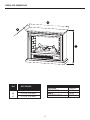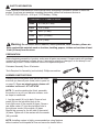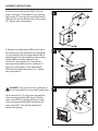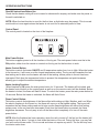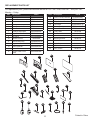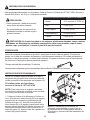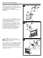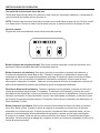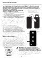
1
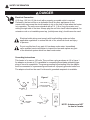
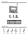
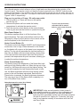
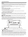
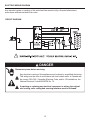
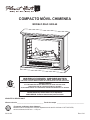
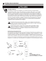
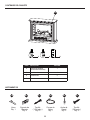
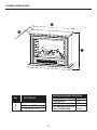
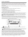
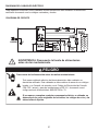
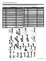
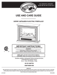
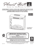
™ COMPACT MOBILE FIREPLACE MODEL #GLF-5002-68 Español p. 16 IMPORTANT INSTRUCTIONS PLEASE READ THIS MANUAL BEFORE INSTALLING AND USING APPLIANCE WARNING! C US IF THE INFORMATION IN THIS MANUAL IS NOT FOLLOWED EXACTLY, AN ELECTRICAL SHOCK OR FIRE MAY RESULT CAUSING PROPERTY DAMAGE, PERSONAL INJURY OR LOSS OF LIFE. INSTALLER: Leave this manual with the appliance. CONSUMER: Retain this manual for future reference. ATTACH YOUR RECEIPT HERE Serial Number ________________________________ Purchase Date _________________________________ Questions, problems, missing parts? Before returning to your retailer, call our customer service department at 1-877-447-4768, 8:30 a.m. –4:30 p.m. CST, Monday – Friday. 20-10-223 1 Rev. 6/14 TABLE OF CONTENTS Safety Information............................................................................................................................. 3 Package Contents............................................................................................................................. 5 Hardware Contents .......................................................................................................................... 5 Fireplace Dimensions ....................................................................................................................... 6 Safety Information ............................................................................................................................ 7 Preparation ....................................................................................................................................... 7 Assembly Instructions ...................................................................................................................... 7 Operating Instructions....................................................................................................................... 9 Care and Maintenance.................................................................................................................... 11 Electric Wiring Diagram................................................................................................................... 12 Troubleshooting............................................................................................................................... 13 Warranty.......................................................................................................................................... 14 Replacement Parts.......................................................................................................................... 15 IMPORTANT: Read all instructions and warnings carefully before starting installation. Failure to follow these instructions may result in a possible electric shock, injury to persons, fire hazard and will void the warranty. Please read the Installation & Operating Instructions before using this appliance. CAUTION PRODUCT DAMAGE MAY OCCUR. Never attempt to disassemble or alter the product in any way not instructed by this manual. 2 SAFETY INFORMATION SAVE THESE INSTRUCTIONS Please read and understand this entire manual before attempting to assemble, operate or install the product. 1. 2. Read all instructions before using this appliance. This appliance is hot when in use. To avoid burns, do not let bare skin touch hot surfaces. If provided, use handles when moving this appliance. Keep combustible materials, such as furniture, pillows, bedding, papers, clothes and curtains at least 3 ft. (914 mm) from the front of this appliance and keep them away from the sides and rear. 3. CAUTION: Extreme caution is necessary when any heater is used by or near children or invalids and whenever the heater is left operating unattended. 4. If possible always unplug this appliance when not in use. 6. Any repairs to this appliance should be carried out by a qualified service person. 5. 7. 8. 9. Do not operate any heater with a damaged cord or plug or after the appliance malfunctions, has been dropped or damaged in any manner. Under no circumstances should this appliance be modified. Parts having to be removed for servicing must be replaced prior to operating this appliance again. Do not use outdoors. This heater is not intended for use in bathrooms, laundry areas and similar indoor locations. Never place this appliance where it may fall into a bathtub or other water container. 10. Do not use this heater in elevated locations, such as on shelves, raised platforms, etc. 11. Do not run cord under carpeting. Do not cover cord with throw rugs, runners or the like. Arrange cord away from traffic areas and where it will not be tripped over. 12. To disconnect this appliance, turn controls to the off position, then remove plug from outlet. 13. Connect to properly grounded outlets only. 14. This appliance, when installed, must be electrically grounded in accordance with local codes, with the current CSA C22.1 Canadian Electrical codes or for USA installations, follow local codes and the National Electric Code, ANSI/NFPA No. 70. 15. Do not insert or allow foreign objects to enter any ventilation or exhaust opening as this may cause an electric shock, fire or damage to the appliance. 16. To prevent possible fire, do not block air intakes or exhaust in any manner. Do not use on soft surfaces, like a bed, where openings may become blocked. 17. This appliance has hot and arcing or sparking parts inside. Do not use it in areas where gasoline, paint or flammable liquids are used or stored. This appliance should not be used as a drying rack for clothing, nor should Christmas stockings or decorations be hung on or near it. 18. Use this appliance only as described in this manual. Any other use not recommended by the manufacturer may cause fire, electric shock or injury to persons. 19. Always plug heaters directly into a wall outlet/receptacle. Always plug the unit into a wall outlet/ receptacle. An extension cord or re-locatable power tap, (outlet/power strip), should never be used. 20. Do not use this heater with missing, damaged, or broken wheels. 21. "SAVE THESE INSTRUCTIONS" 3 SAFETY INFORMATION DANGER Electrical Connection A 15 Amp, 120 Volt, 60 Hz circuit with a properly grounded outlet is required. Preferably, the item will be on a dedicated circuit as other appliances on the same circuit may cause the circuit breaker to trip or the fuse to blow when the heater is in operation. The unit comes standard with a 6 ft. (1.8 m) long, three-wire cord, exiting the right side of the item. Always plug the unit into a wall outlet/receptacle. An extension cord or re-locatable power tap, (outlet/power strip), should never be used. Electrical outlet wiring must comply with local building codes and other applicable regulations to reduce the risk of fire, electrical shock and injury to persons. Do not use this item if any part of it has been under water. Immediately call a qualified service technician to inspect the item and replace any part of the electrical system which has been under water. Grounding Instructions This heater is for use on 120 volts. The cord has a plug as shown at (A) in figure 1. An adaptor as shown at (C) is available for connecting three-blade grounding-type plugs to two-slot receptacles. The green grounding lug extending from the adaptor must be connected to a permanent ground such as a properly grounded outlet box. The adaptor should not be used if a three-slot grounded receptacle is available. 1 Figure 1 (A) METAL SCREW COVER OF GROUNDED OUTLET BOX GROUNDING PIN (B) ADAPTER (C) GROUNDING MEANS GROUNDING PIN (D) 4 NOTE: Adaptors are NOT for use in Canada. PACKAGE CONTENTS A C B Part Description D Quantity A Mantel (with fireplace insert) 1 B Front Caster 2 C Rear Brake Caster 2 D Remote Control 1 HARDWARE CONTENTS AA Wrench Qty. 1 BB Mounting Bracket Qty. 2 CC 1-3/8” Screw Qty. 2 5 DD EE Nylon Strap Qty.1 Wall Anchor Qty. 2 FF 5/8” Screw Qty. 2 FIREPLACE DIMENSIONS A B C R ef. TECHNICAL SPECIFICATIONS VOLTAGE120V AC FREQUENCY 60HZ AMPS12.5A HEATER RATING 1350W GLF-5002-68 A 31.75 in. (806 mm) B C 12.75 in. (324 mm) 27.75 in. (750 mm) 6 SAFETY INFORMATION Please read and understand this entire manual before attempting to assemble, operate or install the product. If you have any questions regarding the product, please call customer service at 1-877-447-4768, 8:30 a.m. - 4:30 p.m., CST, Monday - Friday. CLEARANCE TO COMBUSTIBLES Sides 2 27/64 (61.5 mm) Floor 0 in. (0 mm) Top 20 in. (51 mm) Front 36 in. (914 mm) Rear 0 in. (0 mm) Warning: Do not install unit on shelves, raised platforms, beds, blankets, pillows etc. Keep combustible materials such as furniture, bedding, papers, clothes and curtains at least 3 feet (914 mm) from the stove. PREPARATION Before beginning assembly of product, make sure all parts are present. Compare parts with package contents list and hardware contents above. If any part is missing or damaged, do not attempt to assemble the product. Contact customer service for replacement parts. Estimated Assembly Time: 20 minutes Tools Required for Assembly (not included): Phillips screwdriver ASSEMBLY INSTRUCTIONS Carefully remove all pieces from carton and make sure that you have all parts listed (refer to parts list on page 5). If you are missing parts, please call customer service at 1-877-447-4768 1 AA B NOTE: To avoid scratching the finish, assemble the product on a soft, non-abrasive surface, such as carpet or cardboard. C 1. Lay the mantel (A) on its back. Screw a front caster (B) into the pre-drilled hole in the front-right corner of the mantel (A) base. Screw a rear brake caster (C) into the pre-drilled hole in the right-rear corner of the mantle (A) base. Repeat this process for the left side of the mantel (A) base. Tighten all of the casters with the wrench (AA) provided. A NOTE: Installing casters is highly recommended as using fireplace without casters could impede air flow and cause fan heater failure. 7 AA B CC ASSEMBLY INSTRUCTIONS 2. Attach a mounting bracket (BB) to the top edge of the back of the mantel (A) by inserting two screws (FF) through the mounting bracket (BB) and into the pre-drilled holes in the mantel (A). Tighten with a screwdriver. 2 FF BB A FF BB 3. Attach a mounting bracket (BB) to the wall in the location you have selected to put the mantel (A) by positioning the mounting bracket (BB) at approximately the same height as the mounting bracket (BB) previously attached to the mantel (A). Insert screws (CC) through the mounting bracket (BB) and into a wall stud. If there is no stud present, insert wall anchors (EE) before inserting the screws (CC). Tighten with a screwdriver. 3 EE BB CC DANGER: This product is only a deterrent. It is not a substitute for proper adult supervision. Set the mantel (A) 2-3 inches from the wall with both mounting brackets (BB) aligned. Slip the nylon strap (DD) through the openings in each of the mounting brackets (BB) and secure the nylon strap (DD). This will help prevent the mantel from tipping. 4 CC DD BB FF 8 BB OPERATING INSTRUCTIONS Read All Instructions Before Use Check that the heater outlet grill is not covered or obstructed in anyway, and make sure the power to the unit is switched on. NOTE: When the heat function is used for the first time, a slight odor may be present. This is normal and should not occur again unless the heater is not used for an extended period of time. Control Panel The control panel is located on the front of the fireplace. Main Power Button: This button supplies power to all the functions of the log set. The main power button must be in the ON position, either from the remote or controls on the log set for the functions to work. Heater Control Button: This button controls the heater ON/OFF and 5 temperature modes from Low to High. When the heater is first turned on, it will come on at the lowest temperature setting. The log set will remember the last heat setting and in later use the heater will start at that setting, unless power to the unit has been interrupted. Each time the temperature button is pressed, the temperature set point increases, allowing you to adjust the ambient temperature. Heater Locking Function: When fireplace is ON, press the main power button for 10 seconds. The heater will be locked, and the heater control button on the control panel as well as on the remote control will be disabled. Before the heater is locked, the flame will flash 6 times. To unlock the heater, press the main power button for 10 seconds. Before the heater is unlocked, the flame will flash 6 time. Flame Control Button: This button controls the brightness of the flame effect with settings at High, Medium, and Low. When the electric fireplace is first turned on, the flame will come on at the highest setting. The log set will remember the last flame setting used and in later use the flame brightness will start at that setting, unless power to the unit has been interrupted. Each time the flame button is pressed, the flame brightness decreases. The only way to turn off the flame effect completely is to turn off the main power button. NOTE: After the fireplace has been operating, when the unit is turned off, the fan (not the heater) will continue to run for about 1 minute to cool down the interior of the unit. During this time, you may feel cool air from the blower outlet. This is normal and does not require any action. The fan will stop once the interior cools down. 9 OPERATING INSTRUCTIONS The infrared remote control relies on a line of sight and must be pointed at the controls of the log set to work. The remote control unit has the controls required to turn ON/OFF both the main power and the heater. If you prefer to use the control buttons on the log set unit itself, they are on the lower right corner of the unit. The layout of the buttons and remote control unit can be seen in Figures 2 and 3, respectively. Plug your log set into a 15-amp, 120-volt power outlet. 1. Turn the power on. Flame will show on the wall be hind the log set. 2. Remove the plastic tab from inside the battery compartment to activate the remote control. 3. Point the remote control directly at the control buttons of the log set and use the buttons to operate the log set. The plastic tab inside the battery compartment MUST be removed before the remote control will operate. (Pull tab) Main Power Button (1): This button supplies power to all the functions of the electric fireplace. The main power button must be in the ON position, either from the remote or the controls on the electric fireplace for the functions to work. Heater Control Button (2): This button controls the heater ON/OFF and 5 temperature modes from Low to High. When the heater is first turned on, the heater will come on at the lowest room temperature setting. The log set will remember the last heat setting. In later use, the heater will start at that setting, unless power to the unit has been interrupted. Each time this button is pressed, the temperature set point increases, allowing you to adjust the ambient temperature. Flame Control Button (3): This button controls the brightness of the flame effect with settings at High, Medium and Low. When the log set is first turned on, the flame will come on at the highest setting. The log set will remember the last flame setting used. In later use, the flame brightness will start at that setting, unless power to the unit has been interrupted. Each time the Flame button is pressed, the flame brightness decreases. The only way to turn off the flame effect completely is to turn off the Main Power button. Figure 3 1 2 3 Battery Procedure: (Size CR2025) BatteryReplacement replacement instruction CR2025 OPEN PUSH RELEASE IMPORTANT: Under normal operation, when power is interrupted from either an outage or from unplugging unit from wall while still in operation, the heat level indicator lights may blink repeatedly and the unit will cease operation. In order to reset the unit, unplug for 10 minutes, then plug back in and operate normally in accordance with the Use and Care Guide. 10 CARE AND MAINTENANCE Cleaning Always turn the heater OFF and unplug the power cord from the outlet before cleaning. Use a vacuum or duster to remove dust and dirt from the heater and vent areas. To maintain the finish, clean with a soft, slightly damp cloth and buff with a dry cloth. Never use abrasive cleansers, liquid sprays, or any cleaner that could scratch the surface. Never drag the unit across a floor. The added stress from dragging the unit may cause the legs to break. Glass Information (some models) 1. Under no circumstances should this product be operated with broken glass. 2. Do not strike or slam the glass. 3. Do not use abrasive cleaners to clean the glass. 4. This product uses tempered glass. Replacement of the glass supplied by the manufacturer should be done by a qualified service person. Light Bulb Inspection and Replacement The flame effect is created by two 40-Watt light bulbs with an E-12 (small) socket base. Use only this type of light bulb. If the flame effect does not work, the bulbs may have come loose or been damaged during shipping. WARNING: Light bulbs become very hot during use. Allow at least 10 minutes for the bulbs to cool before touching. To inspect or replace the bulbs, first unplug the power cord from the outlet. Locate the access panel on the back of the stove. Remove the screws and the panel. Check the bulbs to be sure they are finger tight and in working order. Replace any damaged or faulty bulbs. Reattach the access panel. Do not operate this heater without the access panel in place. Do not remove the back cover of this heater. There are no serviceable parts inside. WARNING: Do not exceed 40 watts per bulb. Use of higher rated bulbs may result in a fire, causing property damage or personal injury. Maintenance of Motors WARNING: Always disconnect the appliance from the main power supply and allow it to cool before any servicing operation. The motors used on the fan heater and flame effect are pre-lubricated for extended bearing life and require no further lubrication. However, periodic cleaning/vacuuming of the appliance around the air intake and exhaust, as well as the fan heater is recommended. For heavy or continuous use, periodic cleaning must be done more frequently. If the heater blows alternating cold and warm air, check the fan for free movement and for debris restricting air flow. If the fan does not move freely, the unit must be turned off and the fan replaced immediately in order to prevent further damage to the unit. 11 ELECTRIC WIRING DIAGRAM Any electrical repairs or rewiring of this unit should be carried out by a licensed electrician in accordance with national and local codes. CIRCUIT DIAGRAM DANGER Disconnect power before servicing. Any electrical re-wiring of this appliance must be done by a qualified electrician. This wiring must be done in accordance with local codes and/or in Canada with the current CSA C22.1 Canadian Electrical Code, and for US installations, the National Electrical Code ANSI/NFPA No. 70. If repairing or replacing any electrical component or wiring, the original wire routing, color coding and securing locations must be followed. 12 TROUBLESHOOTING If you have any questions regarding the product, please call customer service at 1-877-447-4768, 8:30 a.m. –4:30 p.m. CST, Monday – Friday. PROBLEM POSSIBLE CAUSE CORRECTIVE ACTION Heater does not operate. 1. The heater is not plugged in. 1. Make sure the heater is plugged in to a standard 120V outlet. 2. A circuit breaker is tripped or a fuse blown. 2. Check additional appliances on the circuit; ideally the heater should be on a dedicated 15 Amp circuit. 3. Defective ON/OFF switch. 3. Call customer service. 4. Loose wiring. 4. Call customer service. Power light is ON but the flame effect is not visible. 1. Incorrect operation. 1. Refer to operating instructions. 2. Loose light bulb(s). 2. Tighten light bulb(s). 3. Burnt out light bulb(s). 3. Replace light bulb(s). Heater is not operating. 1. Incorrect operation. 1. Refer to operating instructions. 2. Defective heater switch. 2. Call customer service. 3. Defective heater assembly. 3. Call customer service. 4. Loose wiring. 4. Call customer service. 5. Dirty or clogged vents. 5. Unplug the unit. Clear vent area of dust and debris. Wait ten minutes, plug the unit in again and turn on the heater. 6. The thermostat is satisfied. 6. Adjust thermostat clockwise to make room warmer. 1. Defective fan. 1. Call customer service. 2. Defective heater assembly. 2. Call customer service. 3. Dirt/dust on fan. 3. Refer to maintenance section. Excessive noise when the heater is operating. 13 WARRANTY ONE YEAR LIMITED WARRANTY If within one year from the date of original purchase, this item fails due to a defect in material or workmanship, we will replace or repair at our option, free of charge. To order parts or obtain warranty service, call 1-877-477-4768, 8:30 a.m. – 4:30 p.m. CST, Monday – Friday. This warranty does not cover defects resulting from improper or abnormal use, misuse, accident, or alteration. Failure to follow all instructions in the owner’s manual will also void this warranty. GHP Group, Inc. will not be liable for incidental or consequential damages. Some states do not allow the exclsion or limitation of incidental or consequential damages, so the above limitation or exclusion of incidental or consequential damages may not apply to you. This warranty gives you specific legal rights and you may also have other rights which vary from state to state. GHP Group, Inc. 6440 W. Howard St. • Niles, IL • 60714-3302 Notice to the Customer Our quality furniture is built keeping tradition in mind. Variations in actual wood color and finishes which may result from natural characteristics of the wood, such as grain patterns, mineral streaks and the like, are not considered defects. As wood continues to move and age you may notice these slight differences in color, even on different parts of any individual unit. Sound knots and slight surface cracks are true personality of a quality piece of wood furniture. There are several practices we reccomend so that you may maintain your new furniture in top condition. First of all, to maintain the finish, you should clean with a soft, slightly damp cloth and buff with a dry cloth. Secondly, wood furniture should never be dragged across a floor. The added stress from dragging the unit may cause the dragged edge to splinter or it may cause some joints to loosen. Please contact us for any questions or concerns you may have regarding your new piece of furniture. 14 REPLACEMENT PARTS LIST For replacement parts, please call customer service at 1-877-447-4768, 8:30 a.m. –4:30 p.m. CST, Monday – Friday. Part Description Part # Part Description Part # 1 Back Panel EF237916501AC 16 Power Cord & Connector EF24900015AC Synchronous Motor EFES323020ST 2 Flame Panel EF237916502AC 17 3 Glass EF237916503AC 18 Lamp Socket & Bracket EFES323021ST 4 Screen EF237916504AC 19 Fan Heater EF23022501X-14 5 Front Decorative Panel EF237916505AC 20 Access Panel EFES323008ST 6 Front Panel EF237916506AC-14 21 Control Panel Door EF23791AC-14 7 Left Brick Side Panel EF237916507AC 22 Front Caster 8 Right Brick Side Panel EF237916508AC 23 Rear Brake Caster 20-12-487 EF237916509AC 24 Wrench 20-12-488 EF33510AS 25 Mounting Bracket 20-09-518 EF237916510AC-14 26 1-3/8 in. Screw 20-09-518 20-12-486 9 Top Panel 10 Remote Control 11 Main Board (PCB) 12 Logset EF237916511AC 27 Nylon Strap 20-09-518 13 Flame Reflector EF237916512AC 28 Wall Anchor 20-09-518 14 Control Panel EF237916513AC-14 29 5/8 in. Screw 20-09-518 15 Control Panel Circuit Board EF237916514AC 33 22 11 55 88 77 66 44 99 10 10 11 11 16 16 22 22 12 12 24 24 20 20 19 19 26 26 25 25 15 15 15 14 14 18 18 17 17 23 23 13 13 27 27 28 28 21 21 29 29 Printed in China ™ COMPACTO MÓVIL CHIMENEA MODELO #GLF-5002-68 INSTRUCCIONES IMPORTANTES POR FAVOR, LEA ESTE MANUAL ANTES DE LA INSTALACIÓN Y USO DEL DISPOSITIVO ¡ADVERTENCIA! C US SI LA INFORMACIÓN EN ESTE MANUAL NO SE SIGUE CON EXACTITUD, PUEDE RESULTAR UN CHOQUE ELÉCTRICO O INCENDIO OCASIONANDO DAÑOS A LA PROPIEDAD, LESIONES PERSONALES O LA MUERTE. INSTALADOR: Deje este manual con el dispositivo. CONSUMIDOR: Conserve este manual para uso futuro. ADJUNTE SU RECIBO AQUÍ Número de serie ________________________________ Fecha de compra _________________________________ ¿Preguntas, problemas, piezas faltantes? Antes de volver a la tienda, llame a nuestro departamento de servicio al cliente al 1-877-447-4768, de lunes a viernes de 8:30 a.m. –4:30 p.m. 20-10-223 16 Rev. 6/14 ÍNDICE Información de seguridad................................................................................................................ 18 Contenido del paquete ...................................................................................................................... 20 Aditamentos ..................................................................................................................................... 20 Dimensiones de la chimenea.......................................................................................................... 21 Información de seguridad................................................................................................................ 22 Preparación..................................................................................................................................... 22 Instrucciones de ensemblaje........................................................................................................... 22 Instrucciones de operación............................................................................................................. 24 Cuidado y mantenimiento................................................................................................................ 26 Diagrama del cableado eléctrico..................................................................................................... 27 Solución de problemas.................................................................................................................... 28 Garantía.......................................................................................................................................... 29 Lista de piezas de repuesto............................................................................................................ 30 IMPORTANTE: lea con atención todas las instrucciones y advertencias antes de comenzar la instalación. Si no se siguen las instrucciones, se puede provocar una descarga eléctrica, lesiones a personas, riesgo de incendio, lo que anulará la garantía. Lea estas instrucciones de instalación y funcionamiento antes de utilizar el electrodoméstico. PRECAUCIÓN EL DAÑO DEL PRODUCTO PUEDE OCURRIR. Nunca trate de desarmar o alterar este producto sin seguir las instrucciones de este manual. 17 INFORMACIÓN DE SEGURIDAD GUARDE ESTAS INSTRUCCIONES Lea y comprenda completamente este manual antes de intentar ensamblar, usar o instalar el producto. 1. Lea todas las instrucciones antes de usar este electrodoméstico. 2. Este electrodoméstico se calienta cuando está en funcionamiento. Para evitar quemaduras, no toque superficies calientes con la piel desnuda. Si se incluyen, utilice las manijas para trasladar el electrodoméstico. Mantenga materiales inflamables, como muebles, almohadas, ropa de cama, papeles, ropa y cortinas al menos a 914,4 mm (3 pies) de la parte delantera de este electrodoméstico y mantenerlos alejados de los costados y parte trasera.. 3. PRECAUCIÓN: Se debe tener extrema precaución cuando niños o personas discapacitadas usen un calentador o cuando se use cerca de ellos, y siempre que el calentador se deje funcionando sin vigilancia. 4. Si es posible, siempre desenchufe este electrodoméstico cuando no lo use. 5. No opere ningún calentador con un cable o enchufe dañados, o después de fallas del mismo, de que se haya dejado caer o dañado de cualquier forma. 6. Toda reparación de este electrodoméstico debe realizarla un técnico calificado. 7. Bajo ninguna circunstancia se debe modificar este electrodoméstico. Las piezas que se deben retirar para reparación se deben reemplazar antes de volver a hacer funcionar este electrodoméstico. 8. No lo use en exteriores. 9. Este calentador no se debe usar en el baño, lavadero y en espacios húmedos similares interiores. Nunca coloque este calentador donde se pueda caer dentro de una bañera u otro contenedor de agua. 10. No utilice este calentador en lugares elevados como por ejemplo sobre repisas, plataformas elevadas, etc. 11. No coloque el cable debajo de una alfombra. No cubra el cable con alfombras, tapetes o similares. Coloque el cable lejos de zonas de tránsito en donde nadie se pueda tropezar y caer. 12. Para desconectar este electrodoméstico, gire los controles a la posición de apagado y luego retire el enchufe del tomacorriente. 13. Conecte únicamente a un tomacorriente con la debida puesta a tierra. 14. Cuando está instalado, este electrodoméstico se debe poner a tierra según los códigos locales, según los Códigos de Electricidad de Canadá CSA C22.1 o, para instalaciones en EE.UU., siga los códigos locales y el código nacional de electricidad, ANSI/NFPA No. 70. 15. No introduzca objetos extraños ni permita que entren en las aberturas de escape o ventilación, ya que pueden provocar descargas eléctricas, incendios o daños en el electrodoméstico. 16. Para evitar incendios, no bloquee las entradas ni salidas de aire de ninguna manera. No use sobre superficies blandas, como una cama, donde las aberturas se puedan bloquear. 17. Este electrodoméstico tiene en su interior piezas calientes y piezas que forman arcos eléctricos o que echan chispas. No lo use en áreas donde se use o almacene gasolina, pintura o líquidos inflamables. Este electrodoméstico no se debe usar como una rejilla para secar ropa, ni tampoco se deben colgar calcetas navideñas o decoraciones en el electrodoméstico o cerca de éste. 18. Utilice este electrodoméstico sólo como se describe en este manual. Cualquier otro uso no recomendado por el fabricante puede causar incendios, descargas eléctricas o lesiones personales. 19. Siempre conecte las estufas directamente al enchufe/toma de electricidad de la pared. Siempre enchufe la unidad en untomacorriente/receptáculo de la pared. Nunca deben usarse una extensión eléctrica ni un tomacorriente de alimentación reubicable (tomacorriente/enchufe múltiple). 20. No utilice este calentador cuando le falten patas o estén dañadas o rotas. 21. GUARDE ESTAS INSTRUCCIONES. 18 INFORMACIÓN DE SEGURIDAD PELIGRO Conexión eléctrica Se requiere un circuito de 15 amperios, 120 voltios, 60 Hz con un tomacorriente correctamente puesto a tierra. De preferencia, la artículo debe estar en un circuito dedicado, ya que la conexión de otros electrodomésticos al mismo circuito puede provocar que el interruptor de circuito se desconecte o que el fusible se funda cuando el calentador esté en funcionamiento. Se incluye como estándar con la unidad un cable de tres conductores de 1,83 m (6 pies) de largo, que sale del lado derecho de la artículo. Siempre enchufe la unidad en untomacorriente/receptáculo de la pared. Nunca deben usarse una extensión eléctrica ni un tomacorriente de alimentación reubicable (tomacorriente/enchufe múltiple). El cableado del tomacorriente debe cumplir con los códigos de construcción locales y con otras normas que correspondan para reducir el riesgo de incendio, descarga eléctrica y lesiones a personas. No utilice esta artículo si alguna de sus piezas estuvo sumergida en agua. Llame de inmediato a un técnico en mantenimiento calificado a fin de que inspeccione la artículo y reemplace cualquier pieza del sistema eléctrico que haya estado bajo agua. Instrucciones de puesta a tierra Este calentador fue diseñado para su uso en 120 voltios. El cable tiene un enchufe, como se muestra en A de la figura 1. Hay disponible un adaptador, como se muestra en C, para conectar enchufes con puesta a tierra de tres clavijas a receptáculos de dos ranuras. La orejeta verde de puesta a tierra que sale del adaptador se debe conectar permanentemente a tierra, como a través de una caja de un tomacorriente correctamente puesto a tierra. El adaptador no se debe usar si hay disponible un receptáculo de tres ranuras puesto a tierra. Figura 1 TORNILLO DE METAL TAPA DE LA CAJA DEL TOMACORRIENTE PUESTO A TIERRA CLAVIJA CON PUESTA A TIERRA (A) (B) ADAPTADOR (C) PUESTA A TIERRA CLAVIJA CON PUESTA A TIERRA (D) 19 NOTA: Los adaptadores NO son para ser utilizados en Canadá CONTENIDO DEL PAQUETE A C B Pieza Descripción D Cantidad A Marco de la chimenea (con inserto de chimenea) 1 B Rueda frontal 2 C Ruedita frontal 2 D Control remoto 1 ADITAMENTOS AA Llave Qty. 1 BB Soporte de Montaje Qty. 2 CC Tornillo (1-3/8 pulg.) Qty. 2 20 DD EE Correa de Nylon Qty.1 Ancla de Pared Qty. 2 FF Tornillo (5/8 pulg.) Qty. 2 CHIMENEA DIMENSIONES A B C R ef. ESPECIFICACIONES TÉCNICAS VOLTAJE 120V AC FRECUENCIA 60HZ AMPERAJE12.5A POTENCIA DE SERVICIO DEL CALENTADOR 1350W GLF-5002-68 A 806 mm (31.75 in.) B C 324 mm (12.75 in.) 750 mm (27.75 in.) 21 INFORMACIÓN DE SEGURIDAD Lea y comprenda completamente este manual antes de intentar ensamblar, usar o instalar elproducto. Si tiene preguntas relacionadas con el producto, llame al Servicio al Cliente al1-877-447-4768, de lunes a viernes de 8:30 a.m. a 4:30 p.m., hora central estándar. PRECAUCIÓN: • Estufa es pesado y debe ser montado cerca de su ubicación deseada. • Se recomienda que dos personas se desplazan la estufa se reunieron para prevenir lesiones. DISTANCIA DE SEPARACIÓN CON ELEMENTOS INFLAMABLES Lateral 61.5 mm mm (2 27/64 in.) P iso 0 mm (0 in.) Parte superior 51 mm (20 in.) Parte delantera 914 mm (36 in.) Trasero 0 mm (0 in.) PRECAUCIÓN: No instale la unidad en los estantes, plataformas elevadas, camas, mantas, almohadas, etc Mantenga los materiales combustibles, tales como muebles, ropa de cama, papeles, ropa y cortinas por lo menos 3 pies (914 mm) de la estufa. PREPARACIÓN Antes de comenzar a ensamblar el producto, asegúrese de tener todas las piezas. Compare las piezas con la lista del contenido del paquete y los aditamentos anteriores. No intente ensamblar el producto si falta alguna pieza o si éstas están dañadas. Póngase en contacto con el Departamento de Servicio al Cliente para obtener piezas de repuesto. Tiempo estimado de ensamblaje: 20 minutos Herramientas necesarias para el ensamblaje: destornillador Phillips (no se incluye). 1 INSTRUCCIONES DE ENSAMBLAJE AA Retire con cuidado todas las piezas de la caja y asegúrese de que usted tiene todas las piezas de la lista (consulte la lista de piezas en la página 19). Si le faltan piezas, por favor llame servicio al cliente al 1-877-447-4768 NOTA: Para evitar rayar el acabado, ensamble este producto sobre una superficie suave no abrasiva, como una alfombra o cartones. 1. Coloque el marco de la chimenea (A) sobre su lomo. Atornille una ruedita frontal (B) en el agujero preperforado en la esquina frontal derecha de la base del marco (A). Atornille una ruedita de freno trasera (B) en el agujero preperforado en la esquina trasera derecha de la base del marco (A). Repita este proceso para el lado izquierdo de la base del marco (A). Apriete todas las rueditas con la llave (AA) proporcionada. 22 B C A AA B CC NOTA: La instalación de las ruedas es altamente recomendable ya que el uso de la chimenea sin las ruedas podría impedir el flujo de aire y causar la falla del calentador del ventilador. INSTRUCCIONES DE ENSAMBLAJE 2. Instale un soporte de montaje (BB) en el borde superior de la parte trasera del marco (A) insertando dos tornillos (FF) a través del soporte de montaje (BB) y en los agujeros preperforados en el marco (A). Apriete con un destornillador. 2 FF BB A FF BB 3. Instale un soporte de montaje (BB) en la pared en la ubicación que seleccionó para colocar el marco (A) colocando el soporte de montaje (BB) a aproximadamente la misma altura que el soporte de montaje (BB) instalado previamente en el marco (A). Inserte tornillos (CC) en el soporte de montaje (BB) y en un montante de pared. Si no hay montantes, inserte las anclas de pared (EE) antes de insertar los tornillos (CC). Apriete con un destornillador. 3 EE BB CC PELIGRO: Este producto es solo un disuasivo. No es un sustituto de supervisión apropiada de un adulto. 4 CC DD Coloque el marco (A) a 2-3 pulgadas de la pared con ambos soportes de montaje (BB) alineados. Deslice la correa de nylon (DD) a través de las aberturas en cada soporte de montaje (BB) y asegure la correa de nylon (DD). Esto evitará que el producto se incline. 23 BB FF BB INSTRUCCIONES DE OPERACIÓN Lea todas las instrucciones antes de usar Revise que la parrilla de salida de la estufa no este cubierta o haya algun obstaculo, y asegurese de que el boton de encendido este en el punto on. NOTA: Cuando haga funcionar la estufa por primera vez, puede haber un poco de olor. Esto es normal y no debe volver a ocurrir al menos que la estufa este por un extenso periodo de tiempo sin usar. Panel de control El panel de control está ubicado detrás de la puerta de la estufa. Botón de fuente de energía principal: Este botón suministra energía a todas las funciones de la chimenea. Debe encenderse para que la chimenea funcione. Botón de control del calefactor: Este botón controla el encendido y apagado del calefactor y 5 modos de temperatura desde Baja a Alta. Cuando el calefactor se enciende por primera vez, encenderá al ajuste de la temperatura ambiente más baja. El ajuste de registro recordará el último ajuste de calor y en uso posterior el calefactor encenderá a ese ajuste, a menos que se haya interrumpido la energía a la unidad. Cada vez que se presione el botón de temperatura, el punto de ajuste de la temperatura aumenta, permitiéndole ajustar la temperatura ambiente. Función de bloqueo del calefactor: Cuando el calefactor está encendido, presione el botón de la fuente de energía principal durante 10 segundos. El calefactor se bloqueará y el botón de control del calefactor en el panel de control como también el control remoto se inhabilitarán. Antes de que el calefactor se bloquee, la llama destellará 6 veces. Para desbloquear el calefactor, presione el botón de la fuente de energía principal durante 10 segundos. Antes de que el calefactor se desbloquee, la llama destellará 6 veces. Botón de control de la llama: Este botón controla la luminosidad del efecto de llama con ajustes como Alto, Medio y Bajo. Cuando el ajuste de registro se enciende por primera vez, la llama se encenderá en el ajuste más alto. El ajuste de registro recordará el último ajuste de llama y en uso posterior la luminosidad de la llama encenderá a ese ajuste, a menos que se haya interrumpido la energía a la unidad. Cada vez que se presiona el botón de la llama, la luminosidad de la llama disminuye. La única manera de apagar por completo el efecto de la llama es apagando el botón de la fuente de energía principal. 24 INSTRUCCIONES DE OPERACIÓN El control remoto infrarrojo depende de una línea de visión y debe ser apuntado a los controles del conjunto de leños para que funcione. La unidad de control remoto tiene los controles requeridos para encender/apagar tanto la energía principal como el calefactor. Si prefiere usar los botones del control en la unidad misma del conjunto de leños, estos se encuentran en la esquina inferior derecha de la unidad. La disposición de los botones y la unidad de control remoto se pueden ver en las Figuras 2 y 3, respectivamente. Conecte su conjunto de leños en un tomacorriente The plastic tab inside the battery eléctrico de 15 Amperios, 120 Voltios. compartment MUST be removed before the remote control will operate. 1. Encienda la energía. Se mostrará la llama en la pared detrás del conjunto de leños. (Pull tab) 2. Retire la lengüeta plástica del interior del compartimien to de la batería para activar el control remoto. 3. Apunte el control remoto directamente a los botones de control del conjunto de leños y use los botones para operar el conjunto de leños. Botón de fuente de energía principal (1): Este botón suministra energía a todas las funciones de la chimenea eléctrica. El botón de energía principal debe estar en la posición ON, ya sea en el control remoto o en los controles en la chimenea eléctrica para que opere la función. Botón de control del calefactor (2): Este botón controla el encendido y apagado del calefactor y 5 modos de temperatura de Baja a Alta. Cuando el calefactor se enciende por primera vez, encenderá al ajuste de la temperatura ambiente más baja. El conjunto de leños recordará el último ajuste de Figura 3 calor. En uso posterior, el calefactor arrancará a ese ajuste, a menos que se haya interrumpido la energía a 1 la unidad. Cada vez que se presione el botón de temperatura, el punto de ajuste de la temperatura aumenta, permitiéndole ajustar la temperatura ambiente. Botón de control de la llama (3): 2 Este botón controla la luminosidad del efecto de llama con ajustes como Alto, Medio y Bajo. Cuando el conjunto de leños se enciende por primera vez, la llama se encenderá en el ajuste más alto. El conjunto de leños recordará el último ajuste de la llama utilizado. En uso 3 posterior, la luminosidad de la llama arrancará a ese ajuste, a menos que se haya interrumpido la energía a la unidad. Cada vez que se presiona el botón de la llama, la luminosidad de la llama disminuye. La única manera de apagar por completo el efecto de la llama es apagando el botón de la energía principal. Procedimiento de reemplazo CR2025) deInstrucciones la batería: de (Tamaño reemplazo de la batería CR2025 ABIERTO PRESIONAR LIBERAR IMPORTANTE: Bajo condiciones de funcionamiento normal, cuando se desconecta la energia eléctrica por un corte de corriente o porque se desenchufa la unidad de la pared mientras esta todavia funcionando, la luz indicadora del nivel de temperatura va a parpadear repetidamente y la unidad dejara de funcionar. Para poder reconfigurar la unidad, desenchufela por 10 minutos, luego enchufela otra vez y hagala funcionar normalmente y de acuerdo a la Guía de Uso y Mantenimiento. 25 CUIDADO Y MANTENIMIENTO Limpieza Siempre apague la estufa y desconecte el cable de electricidad de la pared antes de limpiarla. Use una aspiradora o plumero para sacarle el polvo de la toma de aire. Limpiela con un trapo humedo y sequela con un trapo seco. Nunca use limpiadores abrasivos, sprays or limpiadores que puedan rayar la superficie. No arrastre nunca la unidad por el piso. La tensión adicional por arrastrar la unidad puede ocasionar que las patas se quiebren. Información sobre el vidrio 1. Bajo ninguna circunstancia este producto se debe operar con el vidrio roto. 2. No golpee el vidrio. 3. No use limpiadores abrasivos para limpiar el vidrio. 4. Este producto usa vidrio templado. El reemplazo del vidrio proporcionado por el fabricante sólo debe realizarlo un técnico calificado. Inspeccion del foco y reemplazo (algunos modelos) El efecto de la llama es creado por does 40v focos con un E-12 chico de base. Use solo este tipo de foco. Si el efecto de la llama no funciona, los pueden estar flojos o dañados durante el transporte. CUIDADO: Los focos se calientan durante el uso. Espere por lo menos 10 minutos para que los focos se enfrien antes de tocarlos Para inspeccionar or reemplazar los focos, primero desenchufe el cable electrico de la pared. Encuentre el panel de acceso detras de la estufa. Quite los tornillos y el panel. Revise los focos para asegurarse que estan bien ajustados y en buen estado. Reemplaze los que esten dañados. Vuelva a colocar el panel de acceso. No opere la estufa sin el panel en su lugar. No quite la tapa de atras de la estufa. No hay partes que necesiten mantenimiento adentro. CUIDADO: No exceda los 40 w por foco. Eso puede provocar incendio y daños fisicos. Mantenimiento de los motores CUIDADO: Siempre desconecte el electrodoméstico del suministro eléctrico principal y permita que se enfríe antes de cualquier operación de mantenimiento. Los motores usados en el calentador de ventilador y el soplador de llamas vienen lubricados previamente para prolongar la vida útil de los rodamientos y no necesitan otra lubricación. Sin embargo, se recomienda una limpieza o aspiración periódica del electrodoméstico alrededor de la entrada y salida de aire, así como del calentador de ventilador. Para un uso pesado o continuo, la limpieza periódica se debe realizar con mayor frecuencia. Si el calentador sopla alternadamente aire frío y cálido, compruebe que el ventilador se mueva libremente y que no haya desechos que obstruyan el flujo de aire. Si el ventilador no se mueve libremente, la unidad se debe apagar y el ventilador se debe reemplazar inmediatamente para evitar daños a la unidad. 26 DIAGRAMA DEL CABLEADO ELÉCTRICO Toda reparación eléctrica o nuevo cableado de esta unidad sólo debe realizarlo un electricista certificado de acuerdo con los códigos nacionales y locales. DIAGRAMA DE CIRCUITO ADVERTENCIA: Desconecte la fuente de alimentacion antes de dar mantenimiento. PELIGRO Desconecte de la alimentación antes de realizar mantenimiento. Todo nuevo cableado eléctrico del electrodoméstico debe realizarlo un electricista calificado. Este cableado se debe realizar de acuerdo con códigos locales o, en Canadá, de acuerdo con el Código de Electricidad de Canadá CSA C22.1 actual, y para las instalaciones en EE.UU., de acuerdo con el código nacional de electricidad, ANSI/NFPA No. 70. Si se repara o reemplaza cualquier componente eléctrico o cableado, se deben seguir las rutas originales de los cables, los códigos de color y las ubicaciones de fijación. 27 SOLUCIÓN DE PROBLEMAS Si tiene preguntas relacionadas con el producto, llame al Servicio al Cliente al 1-877-447-4768, entre 8 h 30 et 16 h 30, HNC, du lundi au vendredi. Problema Causa posible Acción correctiva La chimenea no funciona. 1.La chimenea no está enchufada. 1.Asegúrese de que la chimenea esté enchufada a un tomacorriente estándar de 120 V. 2.Un interruptor de circuito se desconectó o se fundió un fusible. 3.Interruptor de ENCENDIDO/ APAGADO defectuoso 4.Cableado suelto. 2.Compruebe si hay otros electrodomésticos conectados al circuito; idealmente, la chimenea debe estar conectada a un circuito dedicado de 15 amperios. 3.Llame a Servicio al Cliente. 4.Llame a Servicio al Cliente. La luz de encendido 1.Funcionamiento incorrecto. está encendida pero 2.Desajuste foco de luz. la llama posterior no brilla o no está 3.Focos de luz quemados. visible. 1.Consulte las instrucciones de operación. El calentador no funciona. 1.Funcionamiento incorrecto. 1. Consulte las instrucciones de operación. 2. Interruptor del calentador defectuoso. 2. Llame a Servicio al Cliente. 3. Ensamble del calentador defectuoso. 4. Cableado suelto. 5.Rejillas de ventilación sucio u obstruido. Ruido excesivo cuando el calentador está funcionando. 2. Ajustar foco de luz. 3. Reemplazar foco(s) de luz. 3. Llame a Servicio al Cliente. 4. Llame a Servicio al Cliente. 5. Desenchufe la unidad. Limpie el polvo y los desechos del área de las rejillas de ventilación. Espere diez minutos, vuelva a enchufar la unidad y encienda el calentador. 6. El termostato está satisfecho. 6. Ajuste el termostato en el sentido de las manecillas del reloj para hacer que la habitación esté más caliente. 1.Ventilador defectuoso. 1.Llame a Servicio al Cliente. 2. Asamblaje de la estufa defectuoso. 2. Llame a Servicio al Cliente. 3. Refiérase a la sección de mantenimiento. 3. Suciedad/polvo en el ventilador. 28 UN AÑO DE GARANTÍA LIMITADA GARANTÍA LIMITADA DE UN AÑO Si un lapso de un año a partir de la fecha de compra original este artículo falla debido a un defecto en el material o la mano de obra, lo reemplzaremos o repararemos sin cargos a nuestra discreción. Para hacer un pedido de las piezas o para obtener el servicio de garantía, llame al 1-877-477-4768, 8:30 a.m. – 4:30 p.m. EST, Monday – Friday. Esta garantía no cubre defectos que sean producto de un uso incorrecto o anormal, uso indebido, accidente o alteración. No seguir todas las instrucciones del manual del propietario también anulará esta garantía. El fabricante no será reponsable de daños accidentales o resultantes. Algunos estados no permiten la exclusión o limitación de los daños accidentales o resultantes, de modo que las limitaciones anteriores pueden no aplicarse en su caso. Esta garantía le otorga derechos legales específicos, pero podría tener también otros derechos que verían según el estado. GHP Group, Inc. 6440 W. Howard St. • Niles, IL • 60714-3302 AVISO PARA EL CONSUMIDOR Nuestros muebles de calidad de fabrican teniendo en mente la tradición. Las variaciones en el color y acabados de la madera, que pueden ser resultado de las características naturales de la misma, tales como el patrón de las vetas, manchas minerales y otros similares, no se consideran defectos. A medida que la madera continúa moviéndose y envejeciendo, usted podrá notar estas ligeras diferencias en color, incluso en diferentes partes de una pieza individual. Los nudos profundos y las pequeñas rajaduras en la superficie indican la personalidad verdadera de una pieza de madera de buena calidad. Existen varias formas que recomendamos para que mantenga sus muebles nuevos en las mejores condiciones. Primero que todo, para mantener el acabado debe limpiar con un paño suave, ligeramente húmedo, y pulir con un paño seco. Además, los muebles de madera nunca deben arratrarse por el piso. el estrés agregado de arrastrar la unidad puede causar que la parte arrastrada se astille o que se afloje una unión. Comuníquese con nostoros si tiene alguna pregunta o preocupación acerca de su nuevo mueble. 29 LISTA DE PIEZAS DE REPUESTO Para obtener piezas de repuesto, llame a nuestro Departamento de Servicio al Cliente al 1-877-447-4768, de lunes a viernes de 8:30 a.m. a 4:30 p.m., hora central estándar. Pieza Descripción Núm. de pieza Pieza Descripción Núm. de pieza 1 Panel trasero EF237916501AC 16 Cable eléctrico y conector EF24900015AC 2 Panel de la llama EF237916502AC 17 Motor sincrónico EFES323020ST 3 Vidrio EF237916503AC 18 EFES323021ST 4 Pantalla EF237916504AC Receptáculo y soporte de lámpara 5 Panel decorativo frontal EF237916505AC 19 Calentador del ventilador EF23022501X-14 6 Panel frontal 20 Panel de acceso EFES323008ST 7 Panel lateral izquierdo de ladrillo EF237916507AC 21 Puerta del panel de control EF23791AC-14 8 Panel lateral derecho de ladrillo EF237916508AC 22 Ruedita frontal 9 Panel superior EF237916509AC 10 Control remoto EF33510AS 11 Tablero principal (PCB) 12 Conjunto de leños EF237916511AC 13 Reflector de llama EF237916512AC 14 Panel de control 15 Tablero de circuito del panel de control EF237916506AC-14 EF237916510AC-14 EF237916513AC-14 EF237916514AC 55 23 Ruedita de freno trasera 20-12-487 24 Llave 20-12-488 25 Soporte de montaje 20-09-518 26 Tornillo de 1-3/8 pulg. 20-09-518 27 Correa de nylon 20-09-518 28 Ancla de pared 20-09-518 29 Tornillo de 5/8 pulg. 20-09-518 33 22 11 20-12-486 88 77 66 44 99 10 10 11 11 16 16 22 22 12 12 24 24 20 20 19 19 26 26 25 25 30 15 15 14 14 18 18 17 17 23 23 13 13 27 27 28 28 21 21 29 29 Impreso en China