1
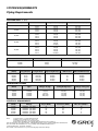
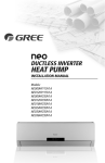
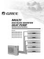
MULTI
DUCTLESS INVERTER
HEAT PUMP
INSTALLATION MANUAL
Models:
MULTI18HP230V1AO
MULTI24HP230V1AO
MULTI30HP230V1AO
MULTI36HP230V1AO
MULTI42HP230V1AO
Thank you for choosing a
Gree Multi Ductless Heat Pump
for your customer.
Please read this installation manual carefully before installing and
starting up the Multi System. Take a moment to fill out the product
and installation form on the back cover. Retain both the manual
and installation record for future reference.
Contents
•
•
•
•
•
•
•
•
•
•
•
•
Safety Precautions
System Requirements
Suggested Tools
Site Instructions
Dimensions
Indoor Unit
Outdoor Unit
Refrigerant Piping
Power and Wiring
Vacuum Testing
Start-up
Troubleshooting
2
4
5
6
7
9
12
13
16
19
21
22
1
SAFETY PRECAUTIONS
Please read the following before installation.
Recognize safety information.
This is the safety-alert symbol. When you see this
symbol on the unit and in instructions or manuals, be alert to the potential for personal
injury. Understand these signal words: DANGER, WARNING, and CAUTION. These
words are used with the safety-alert symbol.
DANGER identifies the most serious hazards which will result in severe personal injury
or death.
WARNING signifies hazards which could result in personal injury or death.
CAUTION is used to identify unsafe practices which may result in minor personal
injury or product and property damage.
NOTE is used to highlight suggestions which will result in enhanced installation,
reliability, or operation.
NOTE: Your actual heat pump system and related devices may differ from the images
shown in this manual.
This appliance is not intended for use by children without responsible adult supervision.
Proper care should be taken to ensure safety.
WARNING
Heat pumps, air conditioners & heating equipment should be installed, started up, and
serviced only by qualified installers and service technicians. Air conditioning, heat pumps
and refrigeration systems are hazardous due to high voltage electrical components, high
refrigerant pressures, and moving parts.
2
SAFETY PRECAUTIONS
CAUTION
• The unit should be installed and serviced only by trained, qualified installers and service
mechanics. Untrained personnel can perform basic maintenance functions such as
cleaning coils. All other operations should be performed by trained service personnel.
• Owner should be cautioned that children should not play with the appliance.
WARNING
ELECTRICAL SHOCK HAZARD
Failure to follow this warning could result in personal injury or death.
• Before installing, servicing or modifying the system, the main electrical disconnect switch
must be in the OFF position. There may be more than one disconnect switch. Lock out
and tag all switches with a warning label.
General Safety Precautions
• A dedicated power supply circuit should be used in accordance with local electrical
safety regulations and National Electrical Codes (NEC).
• Ensure that the entire system is reliably grounded.
• Use proper size circuit breaker to protect equipment against short circuit and
overload conditions.
• Observe all local codes and regulations.
INSTALLATION SITE INSTRUCTIONS
Proper installation site is vital for correct and reliable operation of the system.
Avoid the following installation locations:
• Strong heat sources, vapors, flammable gas or volatile liquids.
• High-frequency electro-magnetic waves, generated by radio equipment, welders
or medical equipment.
3
SYSTEM REQUIREMENTS
Piping Requirements
OUTDOOR UNITS in (mm)
Unit Size (BtuH)
Liquid Line in (mm)
Suction/Gas Line in (mm)
1/4 (6)
1/4 (6)
1/4 (6)
1/4 (6)
1/4 (6)
1/4 (6)
1/4 (6)
1/4 (6)
1/4 (6)
1/4 (6)
1/4 (6)
1/4 (6)
3/8 (9.5)
1/4 (6)
1/4 (6)
1/4 (6)
1/4 (6)
3/8 (9.5)
3/8 (9.5)
3/8 (9.5)
3/8 (9.5)
3/8 (9.5)
3/8 (9.5)
3/8 (9.5)
3/8 (9.5)
3/8 (9.5)
3/8 (9.5)
3/8 (9.5)
3/8 (9.5)
1/2 (12)
5/8 (16)
3/8 (9.5)
3/8 (9.5)
1/2 (12)
1/2 (12)
5/8 (16)
Port 1
Port 2
Port 1
Port 2
Port 3
Port 1
Port 2
Port 3
Port 4
Port 1
Port 2
Port 3
Port 4
Port 1
Port 2
Port 3
Port 4
Port 5
18,000
24,000
30,000
36,000
42,000
INDOOR UNITS in (mm)
Unit Size (BtuH)
Liquid Line in (mm)
Suction/Gas Line in (mm)
9,000
12,000
18,000
1/4 (6)
1/4 (6)
1/4 (6)
3/8 (9.5)
3/8 (9.5)
1/2 (12)
REFRIGERANT PIPE LENGTHS
Unit Size
(BtuH)
Min Pipe
Length ft(m)
Max Total Pipe
Length ft(m)
Max Equivalent
Pipe Length ft(m)
18,000
24,000
30,000
36,000
42,000
10 (3)
10 (3)
10 (3)
10 (3)
10 (3)
66 (20)
230 (70)
230 (70)
230 (70)
262 (80)
33 (10)
66 (20)
66 (20)
82 (25)
82 (25)
Max Elev btwn
Max Elev btwn
IND Units ft IND & OTD Units ft(m)
16
33
33
50
50
33 (10)
66 (20)
66 (20)
82 (25)
82 (25)
REFRIGERANT CHARGE
Unit Size
(BtuH)
Refrigerant
Type
Factory System
Charge oz (kg)*
Max Pipe Length w/out
adding Refrig ft(m)
Additional
Charge oz/ft (g/m)
18,000
24,000
30,000
36,000
42,000
R-410A
R-410A
R-410A
R-410A
R-410A
48 (1.4)
78 (2.2)
78 (2.2)
102 (2.9)
169 (4.8)
33 (10)
98 (30)
131 (40)
131 (40)
164 (50)
0.2 (20)
0.2 (20)
0.2 (20)
0.2 (20)
0.2 (20)
*Precharge amount for up to 25-ft of refrigerant pipe.
ELECTRICAL REQUIREMENTS
Unit Size
(BtuH)
Voltage
Min Circuit
Amps (MCA)
Max Overcurrent
Protection (MOP)
Main Power
Wire Size (AWG)**
18,000
24,000
30,000
36,000
42,000
208/230v - 1ph 60hz
208/230v - 1ph 60hz
208/230v - 1ph 60hz
208/230v - 1ph 60hz
208/230v - 1ph 60hz
13
20
26
28
29
20
30
45
45
50
12
10
8
8
6
**Main power wire from electrical panel to outdoor unit.
Notes:
1) System must be on a single dedicated circuit.
2) Main power is supplied to the outdoor unit.
3) Use table above to size over current protection.
4) Follow all local building codes and NEC (National Electrical Code) regulations.
Interconnecting Cable: Recommended cable - 14/4 AWG stranded bare copper conductors THHN 600V unshielded wire
Note: Use shield cable if installation is in close proximity of RF and EMI transmitting devices.
Condensate Drain Size: 5/8-in OD 7/16-in ID
Note: Insulate condensate drain hose to prevent sweating and possible water damage.
4
SUGGESTED TOOLS
• Standard Wrench
• Adjustable/Crescent Wrench
• Torque Wrench
• Hex Keys or Allen Wrenches
• Drill & Drill Bits
• Hole Saw
• Pipe Cutter
• Screw drivers (Phillips & Flat blade)
• Manifold and Gauges
• Level
• R410A Flaring Tool
• Clamp on Amp Meter
• Vacuum Pump
• Safety Glasses
• Work Gloves
• Refrigerant Scale
• Micron Gauge
5
INSTALLATION SITE INSTRUCTIONS
Step 1
Installation Site of Indoor Unit
Select a site that allows for the following:
• Ensure the installation complies with the installation minimum dimensions and meets the
minimum and maximum connecting piping length and maximum change in elevation.
• Air inlet and outlet will be clear of obstructions, ensuring proper airflow throughout the room.
• Condensate can be easily and safely drained.
• All connections can be easily made to outdoor unit.
• Indoor unit is out of reach of children.
• A wall strong enough to withstand the full weight and vibration of the unit.
• Filter can be easily accessed for cleaning.
• Leave enough free space to allow access for routine maintenance.
• Install at least 10 ft. (3 m) away from the antenna of TV set or radio. Operation of the air
conditioner may interfere with radio or TV reception in areas where reception is weak.
An amplifier may be required for the affected device.
• Do not install in a laundry room or by a swimming pool.
• Determine if condensate pumps are required to properly drain condensate water from
the indoor units.
Installation Site of Outdoor Unit
Select a site that allows for the following:
• Outdoor location meets all minimum installation distances defined in the Installation
Dimensions section.
• Sound from outdoor unit will not annoy neighbors.
• All connections can be easily made to indoor unit.
• Air inlet and outlet will be clear of obstructions to ensure proper airflow.
• Wall or roof is strong enough to withstand the full weight and vibration of the outdoor
unit (for wall or roof installation only).
• Outdoor unit is out of reach of children and does not obstruct walkways.
• Outdoor unit is not exposed to direct sunlight or strong wind.
• Maintenance and repairs can be easily performed on the outdoor unit.
• Ensure the installation complies with the minimum and maximum connecting piping
length and maximum change in elevation criteria.
6
INSTALLATION DIMENSIONS
Indoor unit
2
3
4
Part Name
1.
2.
3.
4.
5.
6.
7.
8.
1
5
Remote Controller
Front Panel
Air Filter
Horizontal Louver
Wall Hole Sleeve
Insulation
Refrigerant Pipes
Drain Hose
Outdoor unit
6
7
8
7
INSTALLATION DIMENSIONS
Minimum indoor clearances
Ceiling
6 in (0.15m)
5 in
(0.13m)
5 in
(0.13m)
6 ft (1.8m)
Floor
Minimum outdoor clearances
Air inlet
Air outlet
Outdoor Unit
Minimum Distances
in (mm)
A
B
C
D
E
20 (500)
24 (610)
78 (2000)
12 (305)
20 (500)
8
INSTALLATION OF INDOOR UNIT
Step 2
Piping Design and Layout
The piping design and layout are critical factors for the overall performance and reliability of the
system. Find the desired locations for each indoor unit and the outdoor unit.
Ln
H2
L2
H1
L1
Measure and record the piping length (L1,L2, L3….Ln) from the outdoor unit to each indoor unit.
NOTE: Min. refrigerant line length between the indoor and outdoor units is 10 ft. (3 m).
L1=
L2=
L3=
L4=
L5=
Find the indoor units with the greatest vertical distance from the outdoor unit. Measure the maximum
vertical height (H1) from the bottom of the outdoor unit to the bottom of the highest mounted indoor units.
H1=
Find the two indoor units with the greatest vertical distance from each other. Measure the maximum
vertical height (H2) between those two indoor units from bottom of one unit to bottom of the other unit.
H2=
9
INSTALLATION OF INDOOR UNIT
Piping Height Requirements
The system piping layout must take in the constraints of vertical height on system performance. The
outdoor unit has a vertical height limit in which it can properly circulate refrigerant in the system.
H2
H1
L2
L3
...Ln
The maximum elevation (H2) between those
two indoor units from bottom of one unit to
bottom of the other unit must be less than:
The maximum elevation (H1) from the bottom
of the outdoor unit to the bottom of the highest
mounted indoor units must be less than:
Maximum Elevation between
Outdoor to Indoor Unit (H1)
Maximum Elevation between
Indoor Units (H2)
Capacity Size
(BtuH)
Distance
ft (m)
Capacity Size
(BtuH)
Distance
ft (m)
18,000
24,000
30,000
36,000
42,000
33 (10)
66 (20)
66 (20)
82 (25)
82 (25)
18,000
24,000
30,000
36,000
42,000
16 (5)
33 (10)
33 (10)
50 (15)
50 (15)
NOTE: If an indoor unit is below the outdoor unit, install oil traps in the suction/gas pipe every 20 vert. ft (6 m)
L =L1
+
L2
+
+
...Ln
LS
The maximum equivalent pipe length from the outdoor
to the farthest indoor units (LS) must be less than:
Maximum Equivalent Pipe Length
Outdoor to Farthest Indoor Unit (Ls)
The maximum total pipe length making up
the system (LT) must be less than:
Maximum Total
Pipe Length (LT)
Capacity Size
(BtuH)
Distance
ft (m)
Capacity Size
(BtuH)
Distance
ft (m)
18,000
24,000
30,000
36,000
42,000
33 (10)
66 (20)
66 (20)
82 (25)
82 (25)
18,000
24,000
30,000
36,000
42,000
66 (20)
230 (70)
230 (70)
230 (70)
262 (80)
NOTE: The outdoor unit is shipped with a full charge of R-410A refrigerant. The factory charge is based on
25 ft (7.6 m) pipe runs. For pipe runs over this limit, add 0.2 oz/ft (20 g/m) of additional refrigerant.
10
INSTALLATION OF INDOOR UNIT
Step 3
Installation of Mounting Bracket
1. Attach the mounting bracket to the indoor unit.
2. Find the horizontal center of the indoor unit.
3. Mark the center of the indoor unit on mounting bracket for future reference.
NOTE: The center of the mounting bracket is not the center of the indoor unit.
4. Remove the mounting brackets from the indoor unit and position the mounting
bracket on the wall in desired location. Use centering mark on mounting bracket
for centering the indoor unit on the wall.
5. Mounting bracket must be installed horizontally and level right to left.
NOTE: Condensate drain pan has built-in pitch for proper drainage.
6. Secure mounting bracket to wall with a minimum of five screws, evenly spaced to
properly support indoor unit weight.
NOTE: It is recommended to install screw anchors for sheet rock, concrete block,
brick and such type of walls.
Mounting Bracket Diagrams and Dimensions
6 3/4
21 3/8
5 1/8
5 1/8
Φ2 1/8
2
09K and 12K Unit
27 3/8
Right
(Rear piping hole)
7 5/8
2
1/8
Φ
8
1/
1 3/4
Φ2
3 1/8
5 5/8
11 3/4
Left
(Rear piping hole)
1 5/8
1 5/8
Φ2 1/8
1/2
18K Unit
2
4 3/4
11
INSTALLATION OF INDOOR UNIT
Step 4
Drill Hole in Wall for Interconnecting Piping, Drain & Wiring
If indoor unit refrigerant piping is going to exit from the rear:
1. It is recommended that the refrigerant pipe flare connectors extend through the wall
to the outside. In some situations field-fabricated piping extensions will be required to
extend the indoor unit refrigerant flare connections to the outside of the wall.
2. Use mounting bracket diagrams and dimensions to find and mark the proper location
for the wall hole.
If refrigerant piping is going through the right or left side of front panel:
1. Use a small saw blade to carefully cut a U-shaped hole in the side of the front panel.
The hole must be large enough for refrigerant pipes, condensate hose and wires.
2. Determine and mark proper location for wall hole.
3. Use table below to determine recommended wall hole size for your unit size.
Table of Wall Hole Size per Unit Size
Unit Size
(BtuH)
Wall Hole Size (Diameter)
9,000
12,000
18,000
4. Cut the wall hole with a 5° to 10°
downward slant to the outdoors.
5. Insert a wall hole sleeve into hole to
prevent damage to refrigerant pipes,
insulation, condensate drain hose
and wiring.
6. Seal around wall hole sleeve with
caulk or foam to weatherproof.
in
mm
2 1/4
2 1/4
2 3/4
55
55
66
Indoor
Outdoor
Wall
Hole Sleeve
Seal Hole
Hole Size
Wall Hole Diagram
12
OUTDOOR UNIT PREPARATION
Step 5
Install Ground Pad or Wall Hangers
1.
2.
3.
4.
Determine proper location for outdoor unit.
Follow all instructions provided by manufacturer for installing wall hangers or ground pad.
Verify the wall hangers or ground pad can safely support the weight of the outdoor unit.
Verify the wall hangers or ground pad is level and meets all outdoor dimensional clearances.
Install Outdoor Unit Risers
If the outdoor unit requires added elevation above the ground, installing riser legs will provide
a sturdy and stable solution. Follow all instructions provided by manufacturer for installing
riser legs to outdoor unit.
NOTE: Riser legs will also help absorb vibrations and noise while facilitating proper drainage.
WARNING
Florida Wind Load Requirements state that outdoor unit must be anchored to
concrete pad using four 3/8-in diameter Power Wedge Bolt Plus (or equivalent)
with 1-in diameter fender washers. Anchor bolts must be embedded into
3,000 PSI minimum concrete at a distance of 4 1/2-in from any concrete edge.
The concrete thickness must exceed 1.5 times the anchor depth.
Install Condensate Drain for Outdoor Unit
During normal heating and defrost operation,
the outdoor unit will generate condensate water.
The condensate water should be routed to a safe
location through the drain hose.
1. Locate drain hole on bottom of outdoor unit.
2. Install the outdoor drain fitting into hole on
the bottom of outdoor unit as shown.
3. Connect the drain hose to drain fitting.
4. Route drain hose to safe location for proper
drainage of excess condensate water.
Drain Fitting Installation
13
INSTALLATION OF REFRIGERANT PIPING
Step 6
Piping Connections
CAUTION
Use refrigeration grade tubing ONLY. No other type of tubing may be used. Use
of other types of tubing will void manufacturer’s warranty. Make sure there is
enough piping to cover the required length between the outdoor and indoor unit.
Piping Preparation
• Do not open service valves or remove protective caps from tubing ends until all
connections are made.
• Keep tubing free of dirt, sand, moisture and contaminants.
• Use a flexible condensate drain hose to fit over the factory 5/8-inch (16mm) drainage hose.
• Insulate each refrigerant pipe and condensate hose with minimum 3/8” (10 mm) wall
thermal pipe insulation.
NOTE: Insulate condensate hose to prevent sweating which may cause water stains
or wall damage.
• Bind refrigerant pipes, condensate hose and interconnecting wire together with cable
ties at 12 inch intervals.
NOTE: A condensate pump accessory (sold separately) is recommended for the
indoor unit when adequate line pitch cannot be provided for drainage.
14
INSTALLATION OF REFRIGERANT PIPING
Step 6 (Cont’d)
Piping and Drain Hose Connections to Indoor Unit
NOTE: For maximum serviceability, it is recommended to have refrigerant pipe flare
connections and the drain connection on the outside.
1. Feed refrigerant pipes, drain hose and interconnecting wires assembly through wall
hole from outdoor to the indoor space.
2. Set the indoor unit on mounting bracket. Allow the indoor
unit to hinge on the top of the mounting bracket. Do not
lock down bottom of unit to mounting bracket.
3. Adjust the length of the interconnecting wires so that it
can easily reach the indoor unit electrical control box.
Route and fit the interconnecting wires into back side of
indoor unit.
4. Open front cover of indoor unit and remove field wiring terminal block cover.
Route the interconnecting wires to terminal block in control box.
5. Allow interconnecting wires to hang free. Wire
connections will be handled later in these
instructions.
6. Adjust the length of condensate drain hose to
easily meet the drain pipe of the indoor unit.
Make connection and secure with a hose clamp.
Insulate the drainage hose and connection to
prevent sweating.
Field Wiring
Cover
Interconnecting
Wiring
NOTE: Prevent condensate drain hose from sagging or kinking for proper drainage.
7. Adjust the length and carefully bend refrigerant pipes to meet indoor unit refrigerant
pipe connections with proper tools to avoid kinks.
15
INSTALLATION OF REFRIGERANT PIPING
8. Apply a small amount of refrigerant oil to the flare connection on the refrigerant pipes.
9. Properly align piping and tighten flare nut using a standard wrench and a torque wrench
as shown in figure below:
Indoor Unit Piping
Taper Nut
Wrench
Piping
Torque Wrench
10. Carefully tighten flare nuts to correct torque level referring to the following Torque Table:
Torque Table
Pipe Diameter
inch (mm)
Nut Size
inch (mm)
1/4 (6.35)
3/8 (9.5)
1/2 (12.7)
5/8 (15.9)
1/4 (17)
3/8 (22)
1/2 (25)
5/8 (29)
Tightening Torque
ft-lbs
N-m
10 to 13
25 to 30
36 to 45
50 to 60
14 to 18
34 to 42
49 to 61
68 to 82
NOTE: Over tightening may damage flare connections and cause leaks.
11. Apply insulation to refrigerant pipe joints to prevent sweating.
12. Gently and securely lock down bottom of indoor unit to wall mounting bracket.
16
INSTALLATION OF REFRIGERANT PIPING
Step 7
Piping Connections to Outdoor Unit
1. Remove service valve cover (if provided) to access
the service valves and refrigerant ports. The outdoor
unit refrigerant port sizes may vary. See System
Requirement Section for refrigerant port sizes.
2. Carefully bend and adjust length of refrigerant
pipes to meet outdoor unit service valves
connections with proper tools to avoid kinks.
Service
Valve Cover
NOTE: Use proper techniques to cut and re-flare refrigerant pipes, if required.
An R410A Flaring Tool is required for re-flaring refrigerant pipes.
An adapter pipe may be required to transition from the indoor unit to the outdoor unit
refrigerant port. Piping adapters are provided with some models. See table below for factory
provided piping adapter quantity and size:
Capacity Size
(BTUH)
Quantity of
Adapters Provided
Tube Size
(Inch)
18,000
0
None
24,000
30,000
2
2
1
1
1
1
1
2
2
2
2
1
1
1
1
3/8 to 1/2
3/8 to 1/2
1/4 to 3/8
1/2 to 3/8
1/2 to 5/8
3/8 to 1/4
5/8 to 3/8
3/8 to 1/2
1/4 to 3/8
1/2 to 3/8
1/2 to 5/8
3/8 to 1/4
5/8 to 3/8
3/8 to 1/2
5/8 to 1/2
36,000
42,000
NOTE: In some situations, field fabricated piping adapters may be required.
17
INSTALLATION OF REFRIGERANT PIPING
3. Apply a small amount of refrigerant oil to the flare connection on the refrigerant pipe.
4. Properly align piping and tighten flare nut using a standard wrench and a torque
wrench as shown in the indoor piping section.
5. Carefully tighten flare nuts to correct torque level referring to the following Torque Table:
Torque Table
Pipe Diameter
inch (mm)
Nut Size
inch (mm)
1/4 (6.35)
3/8 (9.5)
1/2 (12.7)
5/8 (15.9)
1/4 (17)
3/8 (22)
1/2 (25)
5/8 (29)
Tightening Torque
ft-lbs
N-m
10 to 13
25 to 30
36 to 45
50 to 60
14 to 18
34 to 42
49 to 61
68 to 82
NOTE: Over tightening may damage flare connections and cause leaks.
18
INSTALLATION OF POWER AND WIRING
Step 8
Indoor Unit Interconnecting Wire Connections
WARNING
Disconnect all electrical power to unit including disconnects,
fuses and circuit breakers.
1. Open front cover of indoor unit and remove field wiring terminal block cover.
2. Pull interconnecting wires up from back of indoor unit and position in close to the
terminal block on indoor unit.
NOTE: The indoor unit is powered from the outdoor unit, depending on local code,
a disconnect switch may need to be installed to a power supply circuit.
3. Connect wiring to indoor unit per connection diagram.
NOTE: Record wire colors and terminal references for uses with Outdoor Unit
wire connections.
4. Replace field wiring cover and close front cover of indoor unit.
19
INSTALLATION OF POWER AND WIRING
Step 9
Outdoor Unit Wire Connections
WARNING
Disconnect all electrical power to unit including disconnects,
fuses and breakers.
1. Remove the service panel on right side of the outdoor unit.
2. Insert interconnecting wires and main power wires
through the wire holes on conduit mounting bracket.
3. Secure main power conduit (and interconnecting
wire conduit, if required) with locking nuts to
conduit mounting bracket
4. Open wire clamp/strain relief and adjust wire
lengths for proper connections to the outdoor unit
terminal block.
Multiple Port Conduit
Mounting Panel
(Reference Only)
Interconnecting
Wires
5. Following the same wire color and terminal references
from the indoor unit, tightly connect each interconnecting
wire to the terminal block per wiring diagram below.
Main Power Wires
Multiple Port Cable
Connections
(Reference Only)
NOTE: Crossing interconnecting wires will cause system malfunction and possible damage.
20
INSTALLATION OF POWER AND WIRING
Step 9 (Cont’d)
Multiple Port Wiring Diagram
(Reference Only)
6. Tightly connect main power wires to outdoor unit terminal block per wiring diagram above.
7. Secure all wires inside wire clamp/strain reliefs. Verify wires are secure, not loose and no
external force on wires affects the connections at the terminals.
8. Replace service panel on right side of the outdoor unit.
9. Connect main power wires and conduit to unit. Disconnect switch box per manufacturer’s
instructions, National Electrical Code (NEC) and local electrical codes.
CAUTION
• Electrical disconnecting means must be provided and shall be located
within sight and readily accessible from the unit.
• Failure to follow this caution may result in equipment damage or
improper operation.
• All wires running from the indoor to outdoor unit must comply with
National Electrical Code (NEC) and local codes.
• No wire should be allowed to touch refrigerant tubing, compressor or
any moving parts.
• All wires must be connected firmly to terminal block to avoid unit
malfunction, overheating and possible fire hazard.
21
INSTALLATION OF POWER AND WIRING
Local codes may require a disconnect switch within sight of the indoor unit. Use a DFS Disconnect
Switch Accessory Kit (Part No: DFS-SWITCH-A) to break wires going to the N(1), 2, 3, terminals on
the indoor unit, as shown in the wiring diagram below:
CAUTION
Never break or interrupt the ground wire with a switch or disconnect device.
Setting Master-Slave Indoor Units
Typically, the outdoor unit will respond to the indoor units on a first-come-first-served basis. A single
indoor unit may be programmed at the master zone. The master zone will always have priority over the
other indoor units. Setting an indoor unit as the master zone is not required for system operation.
To set an indoor unit as a master zone, locate master/slave configuration switches on the outdoor main
control board. The switch locations 1, 2, 3, 4, 5 correspond to Indoor units (or Ports) 1, 2, 3, 4, 5. Select the
master zone by setting the desired switch to the “On” position. The other switches need to be set in the
“Off” for slaves. By turning the switch from number to ON, the IDU with ON is set to be the master unit.
NOTE: This function is not valid on the 18,000 BtuH 2-Zone model.
22
VACUUM TESTING
Step 10
Leaking Test
Leak test each indoor unit, one unit at a time. Repeat the leak test sequence for each indoor unit.
1. Connect the charging hose of the manifold valve to charge the end of the low-pressure valve.
2. Add dry nitrogen to a pressure of 200 lbs. Tightly close both high- and low-pressure valves.
3. Leak-test flare fittings with soap bubbles. If no leak is detected, release nitrogen.
Step 11
System Vacuum and Charge
Evacuate each indoor unit, one unit at a time. Repeat the evacuation sequence for each indoor unit.
CAUTION
UNIT DAMAGE HAZARD
Never use the system compressor as a vacuum pump. It may result in equipment damage
or improper system operation.
Refrigerant pipes and indoor coil should be evacuated using the recommended deep vacuum
method of 500 microns. The alternate triple evacuation method may be used if the procedure
outlined below is followed.
NOTE: Always break a vacuum with dry nitrogen.
Using Vacuum Pump
1. Completely tighten flare nuts A, B, C, D,
connect manifold gauge charge hose to a
charge port of the low side service valve.
Indoor Unit
Refrigerant
Outdoor Unit
Low Side
High Side
Service Valve
Manifold Gauge
2. Connect charge hose to vacuum pump.
3. Fully open the low side of manifold gauge.
See figure at right.
4. Start vacuum pump.
500 microns
Low Side Valve
Charge Hose
High Side Valve
Charge Hose
Vacuum Pump
Low Side Valve
23
VACUUM TESTING
5. Evacuate using either deep vacuum or triple evacuation method.
6. After evacuation is complete, fully close the low side of manifold gauge and stop
operation of vacuum pump.
7. The factory charge contained in the outdoor unit is good for up to 25 ft. (8 m) of line length.
NOTE: For refrigerant lines longer than 25 ft (8 m), add add’l refrigerant per foot of extra
piping up to the maximum allowable length. See System Requirement section on page 4
for more info.
8. Disconnect charge hose from charge connection of the low side service valve.
9. Fully open service valves B and A.
10. Securely tighten caps of service valves.
Deep Vacuum Method
The deep vacuum method requires a vacuum pump capable of pulling a vacuum of 500 microns
and a vacuum gauge capable of accurately measuring this vacuum depth. The deep vacuum
method is the most positive way of assuring a system is free of air and liquid water.
5000
4500
4000
Leak in
System
3500
3000
2500
2000
Vacuum Tight
too Wet
1500
1000
Tight Dry
System
500
Deep Vacuum Graph
24
START-UP
Step 12
Installing Photocatalytic Filter (optional)
1. Lift front panel and remove air filter. (Fig. a).
2. Attach photocatalytic filter onto air filter. (Fig. b).
3. Install air filter as shown; close panel. (Fig. c).
Air Filter
Photocatalytic
Filter
Fig. a
Fig. b
Fig. c
Step 13
Start-up and Checkout
Test Operation
Perform test operation after completing gas leak and electrical safety check.
1. Turn on electrical disconnect to outdoor unit.
2. Push the “ON/OFF” button on Remote Control to begin testing.
NOTE: A protection feature prevents the system from being activated for approx. 3 minutes.
3. Push MODE button, select COOLING, HEATING, FAN mode to confirm all functions.
System Checks
1.
2.
3.
4.
5.
Conceal refrigerant pipes where possible.
Make sure drain hose slopes downward along entire length.
Ensure all refrigerant pipes and connections are properly insulated.
Fasten pipes to outside wall, when possible.
Seal and weatherproof wall hole which the interconnecting wires and refrigerant pipes
pass through.
25
START-UP
Indoor Unit
1.
2.
3.
4.
Do all Remote Control buttons function properly?
Do the display panel lights work properly?
Does the swing louver function properly?
Does the drain work?
Outdoor Unit
1. Push the mode button to COOL and adjust the room setting to 61° F deg. Wait up to 3 minutes
from compressor time guard. Does compressor and outdoor fan turn on in cooling mode?
2. Push the mode button to HEAT and adjust the room setting to 85° F deg. Wait up to 3 minutes
for compressor time guard. Does compressor and outdoor fan turn on in heat mode?
Explain Following Items To Customer With The Aid Of The Owner’s Manual:
1. How to turn system on and off; selecting COOLING, HEATING and other operating modes;
setting a desired temperature; setting the timer to automatically start and stop system
operation; and all other features of the Remote Control and display panel.
2. How to remove and clean the air filter.
3. How to set air with the swing louvers.
4. Explain care and maintenance.
5. Present the Owner’s Manual and installation instructions to customer.
26
TROUBLESHOOTING
Troubleshooting
This unit has onboard diagnostics. Informational and error codes will be displayed on the LED display on the
front panel of the indoor unit in place of the temperature display. The unit will provide informational codes
to alert the user of special system operations. Informational codes are not signs of system malfunctions or
failures. The following is a list of system informational codes and descriptions:
Description
Info Code
Possible Causes
Mode Conflict
E7
Some Indoor Units are Requesting Heat and Some cooling.
Defrosting
H1
Defrosting Indoor Coil during Heating Mode
Error codes are an indicator of a system malfunction or failure. The following list of error codes and descriptions:
Equipment Fault
Error Codes
Possible Causes
Indoor Ambient Temp. Sensor
F1
Short/Open of the Indoor Ambient Temperature Sensor
Indoor Evaporator Temp Sensor
F2
Short/Open of the Indoor Evaporator Temperature Sensor
Outdoor Ambient Temp Sensor
F3
Short/Open of the Outdoor Ambient temp Sensor
Outdoor Coil Temp Sensor
F4
Short/Open of the condenser coil Temperature Sensor
Outdoor Discharge Air Temp Sensor
F5
Short/Open of the Outdoor Discharge Temperature Sensor
Liquid Valve Inlet Temp Sensor
b5
Short/Open of the liquid valve Temperature Sensor
Suction/Gas Valve Outlet Temp Sensor
b7
Short/Open of the gas valve Temperature Sensor
Indoor Configuration Jumper
C5
Missing Configuration Jumper on Indoor Control Board
High Discharge Temp Protection
E4
Compressor Discharge high Temperature Protection
High Current Protection
E5
Power Supply is not Stable and Voltage Range is too Large
Communication Error
E6
Mis-wired or Communication Failure between the Indoor and Outdoor units
Overload Protection
E8
Overload Protection
Compressor Overheat Protection
H3
Compressor Thermal Overload Protection
IPM Protection
H5
Module Current Protection(namely IPM Protection)
Indoor fan Malfunction
H6
Indoor Fan Stopped or Running too Slow
Motor Desynchronizing
H7
Compressor Desynchronizing
PFC Error
Hc
PFC Protection
Startup Failure
Lc
Compressor Startup Failure
Phase Loss
Ld
Compressor phase Failure/Reverse Protection
Indoor/Outdoor Mismatch
LP
Indoor and Outdoor Units Unmatched (Model or Capacity)
Compressor Current Protection
P5
Phase Over-Current Protection
Radiator Temp Sensor Error
P7
Short/Open Circuit of the Module Temperature Sensor
Radiator Overheat Protection
P8
Module Temperature Protection
4-Way Valve Malfunction
U7
Bad Connection, Solenoid Failure or Valve Malfunction
High Pressure Protection
E1
Too much refrigerant or High Ambient conditions or low airflow.
27
APPENDIX A
Authorized Indoor Unit Combinations
18,000 BtuH
Indoor Unit Size
Dual Configuration
2 Zones
9K+9K
9K+12K
24,000 BtuH
Indoor Unit Size
Dual Configuration
2 Zones
9K+9K
9K+12K
9K+9K
9K+12K
9K+18K
12K+12K
12K+18K
18K+18K
Tri-Configuration
3 Zones
9K+9K+9K
9K+12K+12K
9K+9K+12K
9K+9K+18K
12K+12K+12K
30,000 BtuH
Indoor Unit Size
Dual Configuration
2 Zones
Tri-Configuration
3 Zones
Quad-Configuration
4 Zones
9+9
9+12
12+12
9+18
12+18
18+18
30,000 BtuH
Dual Configuration
2 Zones
Tri-Configuration
3 Zones
9+9+9
9+9+12
9+12+12
9+9+18
12+12+12
9+12+18
12+12+18
9+9+9+9
9+9+9+12
9+9+12+12
Quad-Configuration
4 Zones
Indoor Unit Size
9+9
9+12
9+18
9+21
9+24
12+12
12+18
12+21
12+24
18+18
18+21
18+24
21+21
21+24
24+24
9+9+9
9+9+12
9+9+18
9+9+21
9+9+24
9+12+12
9+12+18
9+12+21
9+12+24
9+18+18
9+18+21
9+18+24
9+21+21
12+12+12
12+12+18
12+12+21
12+12+24
12+18+18
12+18+21
18+18+18
9+9+9+9
9+9+9+12
9+9+9+18
9+9+9+21
9+9+9+24
9+9+12+12
9+9+12+18
9+9+12+21
9+9+18+18
9+12+12+12
9+12+12+18
12+12+12+12
28
APPENDIX A
Authorized Indoor Unit Combinations (Cont’d)
42,000 BtuH
Dual Configuration
2 Zones
Tri-Configuration
3 Zones
Indoor Unit Size
9+12
9+18
9+21
9+24
12+12
12+18
12+21
12+24
18+18
18+21
18+24
21+21
21+24
24+24
9+9+9
9+9+12
9+9+18
9+9+21
9+9+24
9+12+12
9+12+18
9+12+21
9+12+24
9+18+18
9+18+21
9+18+24
9+21+21
9+21+24
9+24+24
12+12+12
12+12+18
12+12+21
12+12+24
12+18+18
12+18+21
12+18+24
12+21+21
12+21+24
12+24+24
18+18+18
18+18+21
18+18+24
18+21+21
21+21+21
42,000 BtuH
Quad-Configuration
4 Zones
Penta Configuration
5 Zones
Indoor Unit Size
9+9+9+9
9+9+9+12
9+9+9+18
9+9+9+21
9+9+9+24
9+9+12+12
9+9+12+18
9+9+12+21
9+9+12+24
9+9+18+18
9+9+18+21
9+9+18+24
9+9+21+21
9+12+12+12
9+12+12+18
9+12+12+21
9+12+12+24
9+12+18+18
9+12+18+21
9+12+21+21
9+18+18+18
12+12+12+12
12+12+12+18
12+12+12+21
12+12+12+24
12+12+18+18
12+12+18+21
9+9+9+9+9
9+9+9+9+12
9+9+9+9+18
9+9+9+9+21
9+9+9+9+24
9+9+9+12+12
9+9+9+12+18
9+9+9+12+21
9+9+9+18+18
9+9+12+12+12
9+9+12+12+18
9+9+12+12+21
9+12+12+12+12
9+12+12+12+18
12+12+12+12+12
29
NOMENCLATURE GUIDE
30
GREE ELECTRIC APPLIANCES, INC.
www.greecomfort.com
LIMITED WARRANTY
GREE distributor (hereinafter “Company”) warrants this product against failure due to defect in materials or workmanship under normal use and maintenance as
follows. All warranty periods begin on the date of original installation. If the date cannot be verified, the warranty period begins one hundred twenty (120) days from
date of manufacture. If a part fails due to defect during the applicable warranty period Company will provide a new or remanufactured part, at Company’s option,
to replace the failed defective part at no charge for the part. This limited warranty is subject to all provisions, conditions, limitations and exclusions listed below.
• Seven (7) years on compressor and Five (5) years on all parts to the original registered end‐user.
• One (1) year warranty on remote controller unit.
• Proper installation – Limited warranty applies only to systems that are installed by a state certified or licensed HVAC contractor, under applicable local and
state law in accordance with all applicable building codes and permits; GREE installation and operation instructions and good trade practices.
• Warranty applies only to products remaining in their original installation location.
• Defective parts must be returned to the distributor through a registered servicing dealer for credit.
LIMITATIONS OF WARRANTIES: ALL IMPLIED WARRANTIES AND/OR CONDITIONS (INCLUDING IMPLIED WARRANTIES OR CONDITIONS OF MERCHANTABILITY
AND FITNESS FOR A PARTICULAR USE OR PURPOSE) ARE LIMITED TO THE DURATION OF THIS LIMITED WARRANTY, SOME STATES OR PROVINCES DO NOT ALLOW
LIMITATIONS ON HOW LONG AN IMPLIED WARRANTY OR CONDITION LASTS, SO THE ABOVE MAY NOT APPLY TO YOU. THE EXPRESS WARRANTIES MADE IN THIS
WARRANTY ARE EXCLUSIVE AND MAY NOT BE ALTERED, ENLARGED, OR CHANGED BY ANY DISTRIBUTOR, DEALER, OR OTHER PERSON, WHATSOEVER.
THIS WARRANTY DOES NOT COVER:
1. Labor or other costs incurred for diagnosing, repairing, removing, installing, shipping, servicing or handling of either defective parts, or replacement parts,
or new units.
2. Normal maintenance as outlined in the installation and servicing instructions or Owner’s Manual, including filter cleaning and/or replacement and lubrication.
3. Failure, damage or repairs due to faulty installation, misapplication, abuse, improper servicing, unauthorized alteration or improper operation.
4. Failure to start due to voltage conditions, blown fuses, open circuit breakers, or damages due to the inadequacy or interruption of electrical service.
5. Failure or damage due to floods, winds, fires, lightning, accidents, corrosive environments (rust, etc.) or other conditions beyond the control of the Company.
6. Parts not supplied or designated by Company, or damages resulting from their use.
7. Products installed outside USA and Canada.
8. Electricity or fuel costs, or increases in electricity or fuel costs from any reason whatsoever, including additional or unusual use of supplemental electric heat.
9. Any cost to replace, refill or dispose of refrigerant, including the cost of refrigerant.
10. Any special, indirect or consequential property or commercial damage of any nature whatsoever. Some states or provinces do not allow the exclusion of
incidental or consequential damages, so the above limitation may not apply to you.
For additional warranty exclusions, visit www.GreeComfort.com.
This warranty gives you specific legal rights, and you may also have other rights which vary from state to state or province to province.
For warranty service or repair, contact your installing contractor. You may find the installer’s name on the equipment or in your Owner’s packet.
Complete product registration below and send back by e‐mail at [email protected]
PRODUCT INFORMATION
Model No.
Serial No.
Date of Installation
Owner Name
Address of Installation
Installing Contractor
Address
Phone No. / E-mail
WSO021513-DLSWARR-HP-Rev 3-8-13
Gree Electric Appliances, Inc ©2014
Cat No: DFS-MULTI-HP-1IN
66129912795