1
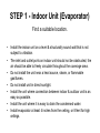
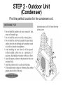
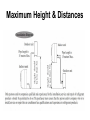
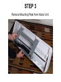
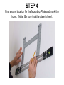
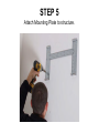
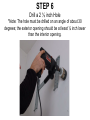
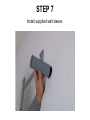
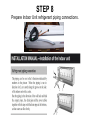
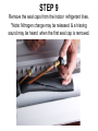
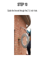
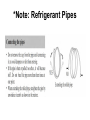
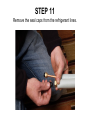
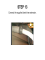
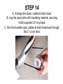
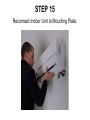
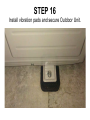
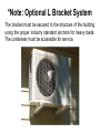
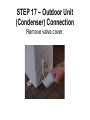
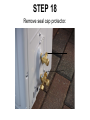
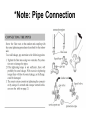
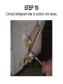
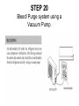
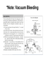
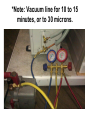
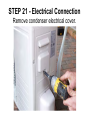
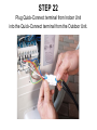
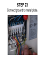
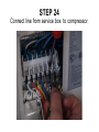
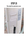
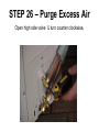
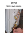
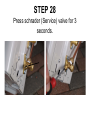
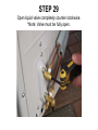
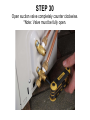
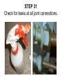
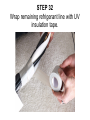
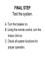
Ductless Mini-Split System
Installation
Tools Required
•
•
•
•
•
•
•
•
Philips Screw Driver
Level
Drill
2 ½ inch Hole Saw
Allen Wrench 5.5 & 6
Vacuum Pump
410 A Gauge
Torque Wrench
STEP 1 - Indoor Unit (Evaporator)
Find a suitable location.
•
•
•
•
•
•
•
Install the indoor unit on a level & structurally sound wall that is not
subject to vibration.
The inlet and outlet ports on indoor unit should not be obstructed; the
air should be able to freely circulate throughout the coverage area.
Do not install the unit near a heat source, steam, or flammable
gas/fumes.
Do not install unit in direct sunlight.
Install the unit where connection between indoor & outdoor unit is as
easy as possible.
Install the unit where it is easy to drain the condensed water.
Install evaporator at least 4 inches from the ceiling, or 8 feet for high
ceilings.
STEP 2 - Outdoor Unit
(Condenser)
Find the perfect location for the condenser unit.
Maximum Height & Distances
STEP 3
Remove Mounting Plate from Indoor Unit.
STEP 4
Find secure location for the Mounting Plate and mark the
holes. *Note: Be sure that the plate is level.
STEP 5
Attach Mounting Plate to structure.
STEP 6
Drill a 2 ½ inch Hole
*Note: The hole must be drilled on an angle of about 30
degrees; the exterior opening should be at least ¼ inch lower
than the interior opening.
STEP 7
Install supplied wall sleeve.
STEP 8
Prepare Indoor Unit refrigerant piping connections.
STEP 9
Remove the seal caps from the indoor refrigerant lines.
*Note: Nitrogen charge may be released & a hissing
sound may be heard when the first seal cap is removed.
STEP 10
Guide the line set through the 2 ½ inch hole.
*Note: Refrigerant Pipes
STEP 11
Remove the seal caps from the refrigerant lines.
STEP 12
Tighten connections using wrenches working in opposite
direction. *Note: For best result use Torque Wrench.
STEP 13
Connect the supplied drain line extension.
STEP 14
A. Arrange the pipes, cables & drain hose.
B. Lag the pipe joints with insulating material, securing
it with supplied UV vinyl tape.
C. Run the bundled pipe, cables & drain hose back through
the 2 ½ inch hole.
*Note: Always keep drain line at
the bottom of bundle.
STEP 15
Reconnect Indoor Unit to Mounting Plate.
STEP 16
Install vibration pads and secure Outdoor Unit.
*Note: Optional L Bracket System
The bracket must be secured to the structure of the building
using the proper industry standard anchors for heavy loads.
The condenser must be accessible for service.
STEP 17 – Outdoor Unit
(Condenser) Connection
Remove valve cover.
STEP 18
Remove seal cap protector.
*Note: Pipe Connection
STEP 19
Connect refrigerant lines to outdoor unit valves.
STEP 20
Bleed/ Purge system using a
Vacuum Pump.
*Note: Vacuum Bleeding
*Note: Vacuum line for 10 to 15
minutes, or to 30 microns.
STEP 21 - Electrical Connection
Remove condenser electrical cover.
STEP 22
Plug Quick-Connect terminal from Indoor Unit
into the Quick-Connect terminal from the Outdoor Unit.
STEP 23
Connect ground to metal plate.
STEP 24
Connect line from service box to compressor.
STEP 25
Re-install the electrical cover.
STEP 26 – Purge Excess Air
Open high side valve ¼ turn counter clockwise.
STEP 27
Remove service valve cap.
STEP 28
Press schrader (Service) valve for 3
seconds.
STEP 29
Open liquid valve completely counter clockwise.
*Note: Valve must be fully open.
STEP 30
Open suction valve completely counter clockwise.
*Note: Valve must be fully open.
STEP 31
Check for leaks at all joint connections.
STEP 32
Wrap remaining refrigerant line with UV
insulation tape.
FINAL STEP
Test the system.
A. Turn the breaker on.
B. Using the remote control, turn the
Indoor Unit on.
C. Check all system functions for
proper operation.