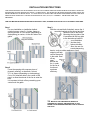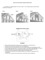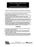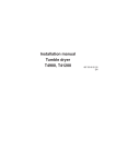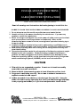
1
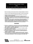
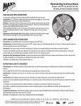
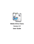
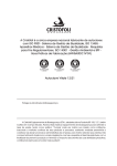
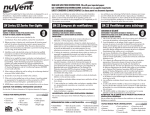
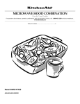
INSTAL I LLATIO ON INST TRUCT TIONS FOR GABLE G MOUNTED VE ENTILA ATORS S V CX2500 0, VX2516, CX11600, VX2515, C CX1500 Models: VX2500, Rea ad all warn nings and instructio ons before e beginnin ng to insta all this fan. FAILU URE TO FOLL LOW THESE INSTRUCTIO ONS COULD D RESULT IN INJURY OR R EVEN DEAT TH 1. Do not attempt to t use this fan with any solid-statte speed co ontrol device e. 2. Use this t unit on nly in the ma anner intended by the manufacturer. If you h have any ques stions, contact the man nufacturer. 3. Before servicing g or cleanin ng this unit, switch pow wer off at th he service p panel and lo ock out to prevent power p from being switc ched on acc cidentally. When serviice disco onnecting means m cann not be locke ed, securely y fasten a p prominent w warning tag to the service s pane el. 4. Insta allation work k and electrrical wiring must be pe erformed by y a qualified d person in acco ordance with h all applica able codes and standa ards, including fire-rate ed construc ction. 5. When n cutting orr drilling intto a wall or ceiling, do not damage electrical wiring and otherr hidden utiilities. 6. The combustion c n airflow ne eeded for sa afe operatio on of fuel-bu urning equipment may y be affec cted by this unit’s operration. Follo ow the heatting equipm ment manuffacture’s guide eline and sa afety standa ards such as a those pu ublished by the Nationa al Fire and Prote ection Asso ociation (NF FPA), and th he American n Society fo or Heating, Refrigeratio on and Air-conditio A oning Engin neers (ASHR RAE), and t he local code authorities. CA AUTION N s unit has an unguarrded prope eller. Do n not use in locations s readily 1. This acce essible to people orr animals. 2. Mount with th he lowest moving m pa arts at lea ast 8 feet a above floo or level. 3. For general g ve entilating use only. Do not us se to exha aust hazarrdous or expllosive matterials and d vapors. 4. Carb bon monox xide is an odorless, colorless s gas that can kill. It may be draw wn into the e house by y operatin ng this fan n if your fu uel-burning g equipme ent is no ot properly y maintain ned, or if you y lack a adequate a attic intak ke vents. VENT TAMATIC, LTD D. 100 WASHING GTON STREE ET, MINERAL W WELLS, TX 760 068-0728 PHONE: (800) 433-1626 - FAX: (940) 325 5-9311 - www.b bvc.com INSTALLATION INSTRUCTIONS THIS GABLE-MOUNTED UNIT IS DESIGNED FOR ATTICS OF AVERAGE SIZE AND OPERATES MOST EFFICIENTLY WHEN AIR INTAKES ARE LOCATED AROUND THE EAVES. ALTERNATIVELY, AIR INTAKE MAY BE FROM OPPOSING GABLE VENTS, BUT NEVER FROM ROOF OR RIDGE VENTS. AT LEAST 600 SQ. IN OF NET FREE AIR INTAKE IS REQUIRED PER UNIT FOR SAFE AND EFFICIENT OPERATION. THE MOTOR OPERATES ON 120 V, 60 HZ, A.C. CURRENT. SEE MOTOR LABEL FOR AMPERAGE. THIS UNIT MAY BE MOUNTED BEHIND ANY STATIC WALL VENT, OR MODELS VX1818 OR CX2121 AUTOMATIC SHUTTERS. Step 1 For new installation or installation behind existing louvers, using 2 x 4 studs, frame an opening at least 18 ¼-in square (depending on stud spacing) on center, on the attic side of the gable. Step 2 Cover the opening with a square piece of plywood, paneling, or sheetrock, at least 21 ¼-in square (depending on stud spacing). Cut a 15-in diameter hole in the center of this panel, to allow the shroud of the fan to enter the hole. It is important to block off any remaining open vent area in the gable. Step 3 With the nuts and bolts furnished, secure the 4 mounting brackets to the shroud and then fasten the unit to the frame. Mounting the long side of the L brackets with the long side to the shroud may better fit your installation and also help reduce vibration. Also, the use of a sound-dampening barrier, such as rubber washers or foam stripping will help reduce resonance in the walls. Seal off any gaps around the fan, in order for the fan to function at maximum efficiency. TIP: MUCH OF THE PREPARATION, WIRING OF THERMOSTAT, TESTING, AND MOUNTING TO THE FRAME CAN BE DONE BEFORE FINAL INSTALLATION IN THE ATTIC. FOR INSTALLATION BEHIND TRIANGULAR GABLE VENTS For installation on triangular gable vents, refer to steps 1-3 on the opposite page and the following illustrations for references. Step 1 Step 2 Step 3 THERMOSTAT INSTALLATION WARNING Before wiring the thermostat, turn the power off at the breaker to avoid electrocution. Be certain to confirm to all Local Electric Codes and Regulations. Remove the cover from the thermostat box and use screws to attach the mounting plate to a stud. When installing the thermostat box, use screws to attach it to the stud to prevent damage to the control. Leave the back side of the control unobstructed to allow free air circulation behind the box. Wire the unit to the incoming power supply according to the diagram below. The thermostat is adjustable. Recommended setting is 90-110 degrees F depending on local temperatures. The fan will run as long as the attic temperature remains above the set temperature. VENTAMATIC, LTD. LIMITED WARRANTY Ventamatic, Ltd. extends this warranty to the original occupying owner of the home where this product is installed that this product will be free from defects of material or workmanship for the time period listed by model number below: VX2500 VX2516 VX2515 LIMITED LIFETIME LIMITED 2-YEAR LIMITED 2-YEAR CX2500 CX1600 CX1500 LIMITED LIFETIME LIMITED 2-YEAR LIMITED 2-YEAR No subsequent purchaser of this product or of the home in which the product is installed is entitled to the benefits of the warranty. Ventamatic, Ltd. will replace the defective part or component only and return the new part to you freight prepaid. Customer must bear all other expenses incurred, including labor required for field repair or replacement and cost of return shipping of the defective part or component to Ventamatic. Customer must also bear the cost of replacement of any part or component and the shipping charges incurred for the replacement and return of any part or component not covered by this warranty, including parts or components damaged by customer. Ventamatic, Ltd. reserves the right to demand and receive written evidence of the date of purchase before undertaking to perform its obligations under this warranty. YOU SHOULD, THEREFORE, RETAIN YOUR SALES SLIP AND ATTACH IT TO YOUR WARRANTY CLAIM. In order to obtain the replacement of a part or component, you must select one of the following methods: A. Return to factory. Return postage prepaid the fan or part you believe to be defective to the address below: Ventamatic, Ltd. 100 Washington Street Mineral Wells, TX 76067 Include your name & address and a copy of your proof of purchase or installation. B. Return to place of purchase. There is no informal dispute settling mechanism available in the event of a controversy involving this warranty. Any and all implied warranties shall be limited to the duration of the express warranty set forth above. In some states, limitations of the duration of implied warranty do not apply. Ventamatic, Ltd. shall not be liable for incidental or consequential damages, whether direct or indirect based upon breach of warranty, breach of contract, negligence or tort. If any suit or other action is brought against Ventamatic by customer, Ventamatic and customer irrevocably waive the right to trial by jury. Purchase and installation of this product constitutes acceptance of the terms of this warranty by customer. Rev. 06/12 2012 VENTAMATIC, LTD.