1
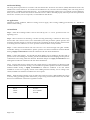
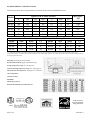
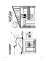
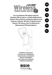
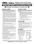
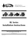
Inline Fans for a Healthier Environment RL Series Installation Instructions Spruce Environmental Technologies, Inc. 3 Saber Way Ward Hill, MA 01835 www.spruce.com P/N IN022-REV J 10/13 RL Series Commercial/Residential Ventilation Fan Installation Instructions Please Read And Save These Instructions. DO NOT CONNECT POWER SUPPLY UNTIL FAN IS COMPLETELY INSTALLED. MAKE SURE ELECTRICAL SERVICE TO FAN IS LOCKED IN "ʺOFF"ʺ POSITION. DISCONNECT POWER BEFORE SERVICING FAN. 1. 2. WARNING – TO REDUCE THE RISK OF FIRE, ELECTRIC SHOCK, OR INJURY TO PERSONS, OBSERVE THE FOLLOWING: a) Use this unit only in the manner intended by the manufacturer. If you have any questions, contact the manufacturer. b) Before servicing or cleaning unit, switch power off at service panel and lock the service disconnecting means to prevent power from being switched on accidentally. When the service disconnecting means cannot be locked, securely fasten a prominent warning device, such as a tag, to the service panel. WARNING – TO REDUCE THE RISK OF FIRE, ELECTRIC SHOCK, OR INJURY TO PERSONS, OBSERVE THE FOLLOWING: a) Installation work and electrical wiring must be done by qualified person(s) in accordance with all applicable codes and standards, including fire rated construction. b) Sufficient air is needed for proper combustion and exhausting of gases through the flue (chimney) of fuel burning equipment to prevent back drafting. Follow the equipment manufacturers guideline and safety standards such as those published by the National Fire protection Association (NFPA), and the American Society for Heating, Refrigeration and Air Conditioning Engineers (ASHRAE), and the local code authorities. c) When cutting or drilling into wall or ceiling, do not damage electrical wiring and other hidden utilities. d) Ducted fans must always be vented to the outdoors. e) If this unit is to be installed over a tub or shower, it must be marked as appropriate for the application and be connected to a GFCI (Ground Fault Circuit Interrupter) – protected branch circuit. f) NEVER place a switch where it can be reached from a tub or shower. 3. CAUTION -‐‑ For General Ventilating Use Only. Do not Use to Exhaust Hazardous or Explosive Materials or Vapors. 4. WARNING -‐‑ Do not use fan to exhaust corrosive gases. 5. WARNING -‐‑ To Reduce The Risk Of Electric Shock, Do Not Expose to Water or Rain. 6. WARNING -‐‑ Check voltage at the fan to insure it corresponds with nameplate. 7. CAUTION -‐‑ To reduce risk of fire and to properly exhaust air, be sure to duct air outside – Do not vent exhaust air into spaces within walls or ceilings or into attics, crawlspaces or garages. 8. NOTICE -‐‑ There are no user serviceable parts located inside the fan unit. Do NOT attempt to open. Return unit to the factory for service. 9. Fan is suitable for use with solid-‐‑state speed controls. If a solid state speed control is used and CSA requirements apply use Pass & Seymour Fan Speed Control 6Amp 120VAC 60Hz 1 Pole Rotary Cat. No. 94601-‐‑I. Page 2 of 8 IN022 Rev J 10. All wiring must be performed in accordance with the National Fire Protection Association’s (NFPA)”National Electrical Code, Standard #70”-‐‑current edition for all commercial and industrial work, and state and local building codes. All wiring must be performed by a qualified and licensed electrician. All wiring must be in accordance with local and national electrical codes. Safety Instructions for RL Series Commercial/Residential Ventilation Fans For Use in Cooking Areas or as Rangehood or Remote Blowers For use in Cooking Areas 1. WARNING – TO REDUCE THE RISK OF FIRE, USE ONLY METAL DUCTWORK. 2. WARNING – TO REDUCE THE RISK OF A RANGE TOP GREASE FIRE: 3. a. Never leave surface units unattended at high settings. Boil over’s cause smoking and greasy spillovers that may ignite. Heat oils slowly on low or medium settings. b. Always turn hood ON when cooking at high heat or when flambéing food (i.e. Crepes Suzette, Cherries Jubilee, Peppercorn Beef Flambé’). c. Clean ventilating fans frequently. Grease should not be allowed to accumulate on fan or filter. d. Use proper pan size. Always use cookware appropriate for the size of surface element. WARNING – TO REDUCE THE RISK OF INJURY TO PERSONS IN THE EVENT OF A RANGE TOP GREASE FIRE, OBSERVE THE FOLLOWINGa: a. SMOTHER FLAMES with a close-‐‑fitting lid, cookie sheet or metal tray, then turn off the burner. BE CAREFUL TO PREVENT BURNS. If the flames do not go out immediately, EVACUATE AND CALL THE FIRE DEPARTMENT. b. NEVER PICK UP A FLAMING PAN – You may be burned. c. DO NOT USE WATER, including wet dishcloths or towels – a violent steam explosion will result. d. Use an extinguisher ONLY if: 1) You know you have a class ABC extinguisher, and you already know how to operate it. 2) The fire is small and contained in the area where it started. 3) The fire department is being called. 4) You can fight the fire with your back to an exit. Based on “Kitchen Fire safety Tips” published by NFPA. a 4. NOTICE -‐‑ USE OF THIS FAN WITHOUT AN ADEQUATE FILTERING SYSTEM IS NOT RECOMMENDED FOR RANGE HOOD APPLICATIONS. 5. 6. If used with a Hood Assembly see Hood Manual To Determine Suitability. Exercise care when cleaning the fan, filters, ductwork etc. Ensure that the power supply is disconnected. Use only cleaning agents or detergents compatible with the surface being cleaned. Obey all instructions applicable to the cleaning agent or detergent. Use all personal protection specified for use with the cleaning agent or detergent including gloves, eye protection, clothing protection etc. Do not mix cleaning agents and/or detergents. Page 3 of 8 IN022 Rev J INSTALLATION INSTRUCTIONS IN022 Rev J RL Series Inline Fan RL600 p/n 23040-‐‑1, p/n 28126 RL500 p/n 23039-‐‑1, p/n 28228 RL450 p/n 23043-‐‑1, p/n 28227 RL350 p/n 23042-‐‑1, p/n 28226 RL300 p/n 23037-‐‑1, p/n 28225 RL200 p/n 23036-‐‑1, p/n 28224 1.0 Mounting The RL Series fan may be mounted at an angle without affecting performance although the vertical mounting position shown in Fig. 1 is highly recommended. If the vertical mounting position is not possible, care should be taken to avoid creating a low spot in the fan/duct system where condensation might accumulate in the fan housing as shown in Fig. 2. In situations where horizontal mounting is desired and condensation is likely to occur (bathroom ventilation in cold climates) this problem might be avoided by mounting the fan 30 degrees beyond horizontal as shown in Fig. 3. Fig. 1 Fig. 2 Fig. 3 2.0 Fan Sealing RL Series fans are factory sealed, no additional caulk or other materials are required to inhibit air leakage. 3.0 Ducting Use only metal ducting for fans used in kitchen areas or as range hood or remote blowers. Any type of ducting is acceptable for areas other than kitchens, however, flexible nonmetallic ducting is recommended for easy installation and quieter operation. Insulated flexible ducting is highly recommended in cold climates to prevent the warm bathroom air from forming condensation in the ducting where it is exposed to colder attic air. To ensure quiet operation of ENERGY STAR qualified in-‐‑line and remote fans, each fan shall be installed using sound attenuation techniques appropriate for the installation. For bathroom and general ventilation applications, at least 8 feet of insulated flexible duct shall be installed between the exhaust or supply grille(s) and the fan. For kitchen range hood remote ventilation applications, where metal duct is generally required by code, a metal sound attenuator shall be installed between the range hood and the fan. The outlet of the fan should always be ducted to the outside. Avoid venting the outlet of the fan directly into an attic area. The excess moisture from the bathroom can cause damage to building structure and any items stored in the attic. Multiple venting points may be connected together using a "ʺT"ʺ or "ʺY"ʺ fitting. Straight smooth runs of rigid metal ducting will present the least resistance and maximize system performance. The Equivalent Length of Rigid Metal Ducting resulting in .2” WC pressure loss for each Fan Model is provided in the specification section of these Instructions. Flexible ducting, if used, must always be as close to being fully extended as possible. Formed rigid metal duct elbows will present the least resistance and maximize system performance, recommended bend radius of elbow is at least 1.5 x duct diameter. For quietest performance, the fan should be mounted further away from the inlet duct, near the outside vent. A minimum distance of 8 feet is recommended between the fan or T/Y of a multi-‐‑intake system and intake grille(s). 4.0 Back Draft Dampers Back draft dampers allow airflow in only one direction preventing cold/hot drafts from entering the vented area and minimize possible condensation and icing within the system while the fan is not operating. Back draft dampers are highly recommended at each intake grille for bathroom ventilation in all cold climate installations. Page 4 of 8 IN022 Rev J 5.0 Electrical Wiring All wiring must be performed in accordance with the National Fire Protection Association’s (NFPA)”National Electrical Code, Standard #70”-‐‑current edition for all commercial and industrial work, and state and local building codes. All wiring must be performed by a qualified and licensed electrician. A Ground Fault Interrupter (GFI) circuit is not required in most installations, check your local codes. Ensure that all exterior electrical boxes are outdoor rated and properly sealed to prevent water penetration into the box. A means, such as a weep hole, is recommended to drain the box. 6.0 Applications Suitable for general ventilation, bathroom venting, fresh air supply, duct boosting, building pressurization, etc. Suitable for kitchen exhaust venting. 7.0 Installation Step 1: Attach the mounting bracket to the fan unit with (2) #10 x ½” screws, provided. Avoid over tightening screws. Step 2: Select location for fan mounting. A location 2/3 along the ducting, a minimum of 10 feet away from the inlet vent to the fan or the Y/T of a multi-‐‑intake system will provide the quietest operation. Fan should be mounted vertically to prevent moisture from accumulating in the fan housing. Attach bracket to mounting structure with the 1 1/4” screws provided. Ensure the fan is securely fastened. Step 3: Connect ductwork between fan inlet and area to be vented through inlet grille. Flexible, nonmetallic ducting is recommended for quietest operation and easiest installation. Insulated flexible ducting is highly recommended for bathroom ventilation in all cold climate installations. Step 4: Connect inlet grille(s). An optional back draft damper may be installed in the inlet grille to prevent cold air from backing into the inlet, prevent conditioned air from escaping and also prevent condensation from forming inside the ductwork. Back draft dampers are highly recommended at each intake grille for bathroom ventilation in all cold climate installations. Step 5: Connect outlet of fan to outside vent. The outside vent may go through the roof, sidewall or soffit as desired. Flexible, nonmetallic ducting is recommended for quietest operation and easiest installation. Insulated flexible ducting is highly recommended for bathroom ventilation in all cold climate installations. As the fan is typically outside of the building thermal boundary, and is venting to the outside, installation of insulation around the fan is not required. Step 6: Make electrical connection to fan. A plastic cable connector such as a T&B #3300may be used to avoid any fitting grounding problem. Observe the proper wiring connections(See Section 4.0). Note that the fan is not intended for connection to rigid metal conduit. RL Series Wire Black White Green Page 5 of 8 AC Connection AC Hot AC Common Ground IN022 Rev J RL SERIES PRODUCT SPECIFICATIONS The following chart shows fan performance for the RL Series Commercial/Residential Fan: Model RL200 RL300 RL350 RL450 RL500 RL600 Max Static, “ WC Typical CFM vs Static Pressure 0 163 268 300 507 545 670 Model RL200 RL300 RL350 0.2 150 240 280 460 500 610 0.5 123 194 238 371 419 513 0.75 101 156 201 298 349 420 1 76 117 164 241 275 329 1.25 54 74 127 193 222 263 1.5 28 34 89 144 170 206 1.78 1.84 2.11 2.27 2.35 2.75 Power Consumption @ 120 VAC , 60Hz (5.0 Amp Max) Duct Watts L.2 Model Duct Watts 4"ʺ 42-‐‑62 15 RL450 8"ʺ 92-‐‑152 6"ʺ 53-‐‑79 45 RL500 10"ʺ 97-‐‑153 6"ʺ 59-‐‑89 34 RL600 12"ʺ 150-‐‑215 L.2 55 140 240 L.2 = Estimated Equivalent Length of Rigid Metal Ducting resulting in .2in WC pressure loss for Duct Size listed. Longer Equivalent Lengths can be accommodated at Flows Lower than that at .2in WC pressure loss (see CFM Vs Static Pressure “WC Table). Do not operate fan above 80% of maximum Static Pressure per performance table. Mounting: Mounting bracket included. Recommended ducting: Rigid or Flexible Ducting. Storage temperature range: 32 -‐‑ 100 degrees F. Normal operating temperature range: -‐‑20 -‐‑ 120 degrees F. Maximum inlet air temperature: 140 degrees F. continuous. Class B Insulation Continuous Duty 3000 RPM Thermally protected Rated for Residential and Commercial use All RL Series Fans Except the RL200 are Energy Star Rated Page 6 of 8 IN022 Rev J Page 7 of 8 IN022 Rev J IMPORTANT INSTRUCTIONS TO INSTALLER Inspect the RL Series Fan for shipping damage within 15 days of receipt. Notify Spruce of any damages immediately. Spruce is not responsible for damages incurred during shipping. However, for your benefit, Spruce does insure shipments. There are no user serviceable parts inside the fan. Do not attempt to open. Return unit to factory for service. Install the RL Series Fan in accordance with all state and local building codes and state regulations. WARRANTY Subject to any applicable consumer protection legislation, Spruce Environmental Technologies, Inc. (“Spruce”) warrants that the RV/RB/DB/RL Series Fan (the “Fan”) will be free from defects in materials and workmanship for a period of five (5) years from the date of manufacture (the “Warranty Term”). Warranty claims made during the first thirty days after installation: Spruce will replace any Fan which fails due to defects in materials or workmanship. The Fan may be returned (at owner’s cost) to either the point of purchase or the Spruce factory. The point of purchase may require proof of purchase or a bill of sales for replacement. Warranty claims made after the first thirty days after installation through the end of the Warranty Term: Spruce will (at its option) either recondition or replace any Fan which fails due to defects in materials or workmanship. The Fan must be returned (at owner’s cost) to the Spruce factory. This Warranty is contingent on installation of the Fan in accordance with the instructions provided. This Warranty does not apply where any repairs or alterations have been made or attempted by others, or if the unit has been abused or misused. Warranty does not include damage in shipment unless the damage is due to the negligence of Spruce. Spruce is not responsible for installation, removal or delivery costs associated with this Warranty. EXCEPT AS STATED ABOVE, THE RL SERIES FANS ARE PROVIDED WITHOUT WARRANTY OF ANY KIND, EITHER EXPRESS OR IMPLIED, INCLUDING, WITHOUT LIMITATION, IMPLIED WARRANTIES OF MERCHANTABILITY AND FITNESS FOR A PARTICULAR PURPOSE. IN NO EVENT SHALL SPRUCE BE LIABLE FOR ANY DIRECT, INDIRECT, SPECIAL, INCIDENTAL, OR CONSEQUENTIAL DAMAGES ARISING OUT OF, OR RELATING TO, THE FAN OR THE PERFORMANCE THEREOF. SPRUCE’S AGGREGATE LIABILITY HEREUNDER SHALL NOT IN ANY EVENT EXCEED THE AMOUNT OF THE PURCHASE PRICE OF SAID PRODUCT. THE SOLE AND EXCLUSIVE REMEDY UNDER THIS WARRANTY SHALL BE THE REPAIR OR REPLACEMENT OF THE PRODUCT, TO THE EXTENT THE SAME DOES NOT MEET WITH SPRUCE’S WARRANTY AS PROVIDED ABOVE. For service under this Warranty, contact Spruce for a Return Material Authorization (RMA) number and shipping information. No returns can be accepted without an RMA. If factory return is required, the customer assumes all shipping cost to and from factory. Spruce Environmental Technologies, Inc. 3 Saber Way Ward Hill, MA 01835 TEL. (978) 521-0901 FAX (978) 521-3964 Record the following information for your records: Serial No. Purchase Date Page 8 of 8 IN022 Rev J