1
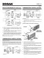
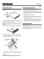
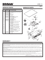
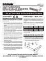
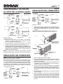
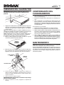
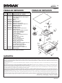
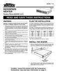
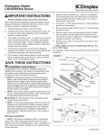
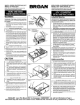
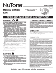
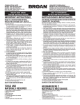
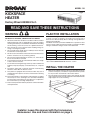
MODEL 114
Page 1
KICKSPACE
HEATER
Factory Wired 240/208 V.A.C.
READ AND SAVE THESE INSTRUCTIONS
WARNING
PLAN THE INSTALLATION
WARNING – TO REDUCE THE RISK OF FIRE, ELECTRIC SHOCK,
OR INJURY TO PERSONS, OBSERVE THE FOLLOWING:
This heater is designed for installation in an enclosed space such
as under a counter or kickspace to provide warm, gentle heat at
the floor level. Reread Safety Notes 3 through 8 for guidelines in
planning the installation.
The Model 114 is factory wired for 240/208 V.A.C. operation. It offers
a choice of heat outputs and can be internally connected for multiple
wattages at different voltages shown in the table below.
1. All electrical work must be done in accordance with local and/or
National Electrical Code as applicable. For safety, this product
must be grounded. If you are unfamiliar with methods of installing
electrical wiring, secure the services of a qualified electrician.
2. Turn off power at service entrance before installing wiring, ser‑
vicing, or cleaning this product.
3. Do not install heater upside down or sideways. Heater must be
located in the horizontal position.
4. Do not recess louvered face of the heater more than three inches
from the vertical face of any overhang (cabinet).
5. Do not locate heater behind doors, furniture, etc., where the air
flow to the unit will be restricted.
6. To avoid electrical shock; do not install heater within arm’s length
of tub or shower enclosure.
7. To avoid motor bearing damage and noisy and/or unbalanced
impellers, keep drywall spray, construction dust, etc., off power
unit.
8. Provide this heater with a separate electrical circuit following
directions under “Wire the Heater” section.
9. This product is equipped with a thermostat which may start it
automatically. Turn off power at service entrance before cleaning
or servicing.
10. This heater includes a visual alarm to warn that parts are getting
excessively hot. If the alarm lights are activated, immediately
turn the heater off and inspect for any objects on or adjacent to
the heater that may cause high temperatures.
11. Please read specification label on product for further information
and requirements.
VOLTS
240
208
120*
120*
WATTS
1500
1125
1500
750
AMPS
6.3
5.4
12.5
6.3
BTU/HR
5120
3840
5120
2560
All ratings are 1‑Phase, 60 Hertz.
*See “FIELD CONVERSION TO 120 V.A.C.” section.
INSTALL THE HEATER
1. Mark the intended mounting location in the base plate under the
counter or kickspace, and remove required material to provide
for easy insertion and removal of the heater cabinet.
2. The unit will be secured in place with screws through the side
angle support brackets. Provide adequate material behind side
angle support for secure mounting.
SIDE
ANGLE SUPPORT
BRACKETS
Installer: Leave this manual with the homeowner.
Homeowner: Use and Care information on page 3.
MODEL 114
Page 2
FIELD CONVERSION TO 120 V.A.C.
THERMOSTAT INSTALLATION
OPTIONAL LINE VOLTAGE WALL-MOUNT THERMOSTAT
1. Locate thermostat on an inside wall away from all drafts and
approximately 4-5 feet above the floor.
2. Route all wiring through the thermostat first and then to the
heater.
OPTIONAL (MODEL 90) UNIT-MOUNT THERMOSTAT
If a 120 V.A.C. circuit is to be used, make wiring changes as follows:
1. Disconnect white wire from heater element terminal “2” and
connect it to terminal “4.” The heater will now operate at 120
V.A.C., 750W, 6.3A.
2. For 120 V.A.C, 1500W, 12.5A operation, add the short red jumper
wire (provided) between terminals “1” and “2”.
3. Remove alarm light wire leads from terminals “1” and “3” of
the high temperature limit. Remove white wire lead from limit
terminal “1” and reconnect at limit terminal “3”. Secure wire leads
with wire tie so there is no interference with unit operation.
NOTE: Terminal numbers are marked on the side of the blower
housing, above the heater elements.
THERMOSTAT INSTALLATION
NOTE: The thermostat control circuit must be wired prior to the
wiring of the heater unit.
This heater may be thermostatically controlled by either a line volt‑
age wall-mounted thermostat (Model 86W), or an optional built-in
thermostat accessory kit (Model 90). Model 90 thermostat kits are
designed for easy installation with this heater. Instructions for in‑
stalling thermostats are provided below and are also supplied with
each thermostat kit.
1. Remove the top cover from the heater.
2. Remove the 5/8” knockout located on the left side of the front
panel (use a screwdriver to remove the knockout). Also remove
the two plastic hole plugs (see illustration).
3. Install thermostat from back side of front panel and fasten in
place, from front, with two screws and washers provided (see
illustrations).
4. Attach temperature control knob by gently pushing it on to the
thermostat shaft. Flats on shaft and knob must line up for proper
installation (do not force control knob onto shaft).
5. Remove black wire from thermal fuse and attach it to thermostat
terminal marked “4”.
6. Remove white wire from temperature limit terminal marked “1”
(Note: the other end of this wire is attached to incoming field
wiring) and attach it to the thermostat terminal marked “1”.
7. Attach black thermostat wire to thermal fuse and white ther‑
mostat wire to the temperature limited marked “3”.
MODEL 114
Page 3
WIRE THE UNIT
CHECK OPERATION
WARNING: Disconnect power at service entrance before wiring
this product.
1. Turn thermostat counterclockwise to its lowest setting.
2. Turn on power to circuit at service entrance.
3. Turn thermostat clockwise. The heating element and fan should
come on. Set thermostat to desired temperature level. During
proper operation, the heater will cycle on and off periodically.
If heater does not come on:
1. Return the thermostat to lowest setting.
2. Shut off power at service entrance.
3. Remove the top cover. Check for proper line voltage and rein‑
spect wiring connections. Reread installation procedure making
sure all steps were followed.
4. Also check the thermal fuse. It may be open and need to be
replaced. Consult the service parts list for the part number of
a replacement fuse. Follow the procedure described in the last
paragraph of the warranty when ordering replacement parts.
1. Run electrical power cable to installation location. Provide two
feet of slack to allow heater to be pulled out far enough to remove
top cover for cleaning or servicing.
NOTE: It is recommended that flexible conduit be used for field wir‑
ing to the unit to protect the wires from sharp objects or hazardous
environments.
NOTE: Be sure supply voltage meets the equipment requirement.
Refer to the rating plate, unit wiring diagram and specification table.
2. Remove top cover for access to wiring box at rear of heater.
3. Remove one of the two knockouts and connect power cable to
heater using appropriate connector. Allow at least six inches of
wiring inside of wiring box.
4. Connect black to black, white to white and green (or bare wire)
to ground screw, as shown. Tuck wires down inside the wiring
box.
5. Replace top cover.
WARNING: Do not operate heater without top cover in place.
6. Slide heater into place and secure to mounting surface.
MAINTENANCE
NOTE: Always disconnect power at service entrance before clean‑
ing or servicing heater.
The only maintenance required for this heater is to periodically
vacuum the front grille and housing. Simply remove the two side
angle support screws, slide heater out, and remove top cover for
access to the blower housing.
MODEL 114
Page 4
SERVICE PARTS
KEY
NO.
1
2
3
4
5
6
7
8
9
10
11
12
13
14
PART
NUMBER
99522899
99522400
99521763
99521765
99020130
99521760
99521761
99271288
99521767
---
99521770
99521768
99521769
*
15
*
16
17
*
*
18
19
*
*
20
*
21
*
22
23
99522062
99522782
SERVICE PARTS
PART DESCRIPTION
Cover (White)
Cycling Thermal Overload Limit Switch
Thermal Fuse
Motor
Blower Wheel
Motor Plate
Element Retainer
Heater Element (2 Required)
Thermostat (Optional)
Housing (White)
Cupped Washer
Strain Relief Bushing
Knob (Optional)
Screw, 6-20 x 1/4 Slotted Hex Head (2 Required)
Screw, 6-20 x 3/8 Slotted Head Head AB Pt.
Nut, 6-32 Hex Keps (2 Required)
Screw, 10-16 x 3/8 Slotted Head Head AB Pt.
Nut, 10-32 Hex Keps (2 Required)
Screw, 10-32 x 1/2 Slotted Head Head Type F
Screw, 6-32 x 3/4 Phillips Pan Head (2 Required) (Optional)
Screw, 8-18 x 1/4 Slotted Pan Head (4 Required)
Plastic Hole Plug (2 Required)
Alarm Light
8
* Standard Hardware. May be purchased locally.
WARRANTY
BROAN-NUTONE ONE YEAR LIMITED WARRANTY
Broan-NuTone warrants to the original consumer purchaser of its products that such products will be free from defects in materials or workmanship for a period of one year from the date of
original purchase. THERE ARE NO OTHER WARRANTIES, EXPRESS OR IMPLIED, INCLUDING, BUT NOT LIMITED TO, IMPLIED WARRANTIES OF MERCHANTABILITY OR FITNESS
FOR A PARTICULAR PURPOSE.
During this one-year period, Broan-NuTone will, at its option, repair or replace, without charge, any product or part which is found to be defective under normal use and service.
THIS WARRANTY DOES NOT EXTEND TO FLUORESCENT LAMP STARTERS AND TUBES. This warranty does not cover (a) normal maintenance and service or (b) any products or
parts which have been subject to misuse, negligence, accident, improper maintenance or repair (other than by Broan-NuTone), faulty installation or installation contrary to recommended
installation instructions.
The duration of any implied warranty is limited to the one-year period as specified for the express warranty. Some states do not allow limitation on how long an implied warranty lasts, so
the above limitation may not apply to you.
BROAN-NUTONE’S OBLIGATION TO REPAIR OR REPLACE, AT BROAN-NUTONE’S OPTION, SHALL BE THE PURCHASER’S SOLE AND EXCLUSIVE REMEDY UNDER THIS
WARRANTY. BROAN-NUTONE SHALL NOT BE LIABLE FOR INCIDENTAL, CONSEQUENTIAL OR SPECIAL DAMAGES ARISING OUT OF OR IN CONNECTION WITH PRODUCT USE
OR PERFORMANCE. Some states do not allow the exclusion or limitation of incidental or consequential damages, so the above limitation or exclusion may not apply to you.
This warranty gives you specific legal rights, and you may also have other rights, which vary from state to state. This warranty supersedes all prior warranties.
To qualify for warranty service, you must (a) notify Broan-NuTone at the address or telephone number below, (b) give the model number and part identification and (c) describe the nature
of any defect in the product or part. At the time of requesting warranty service, you must present evidence of the original purchase date.
Broan-NuTone LLC Hartford, Wisconsin www.broan.com 800-558-1711
Broan-NuTone Canada Mississauga, Ontario www.broan.ca 877-896-1119
99044024C
MODEL 114
MODELO
Página
Page 55
CALEFACTOR PARA
ESPACIOS BAJO GABINETES
Cableado de fábrica: 240/208 VCA
LEA Y CONSERVE ESTAS INSTRUCCIONES
ADVERTENCIA
PLANEACIÓN DE LA INSTALACIÓN
ADVERTENCIA: PARA REDUCIR EL RIESGO DE
INCENDIOS, DESCARGAS ELÉCTRICAS O LESIONES
P E R S O N A L E S O B S E RV E L A S S I G U I E N T E S
PRECAUCIONES:
Este calefactor está diseñado para instalarse en un espacio cerrado
como debajo de un mostrador o gabinete, a fin de suministrar
una calefacción suave a nivel del piso. Lea nuevamente las notas
de seguridad 3 a 8 para conocer las pautas de planeación de la
instalación.
El modelo 114 está cableado de fábrica para funcionamiento con
240/208 VCA. Ofrece una selección de salidas de calor y puede
conectarse internamente para potencias múltiples a los diferentes
voltajes mostrados en la tabla siguiente.
1. Todo trabajo eléctrico debe realizarse de conformidad con los
códigos eléctricos locales y/o nacionales correspondientes. Para
fines de seguridad, este producto debe estar conectado a tierra.
Si usted no está familiarizado con los métodos de instalación
de cableado eléctrico, contrate los servicios de un electricista
calificado.
2. Desconecte la energía eléctrica en la entrada de servicio antes
de instalar el cableado, dar servicio a este producto o limpiarlo.
3. No instale el calefactor en posición invertida ni de lado. El cal‑
efactor debe estar en posición horizontal.
4. La cara con rejillas del calefactor no debe quedar empotrada
a una distancia mayor de 3 pulgadas (7.5 cm) del borde de
cualquier superficie superior (gabinete).
5. No ponga el calefactor en sitios donde estaría restringida la cor‑
riente de aire a la unidad, como detrás de puertas o muebles,
etc.
6. Para evitar descargas eléctricas, no instale el calefactor a menos
de un brazo de distancia de una bañera (tina) o ducha.
7. Para evitar daños a los cojinetes del motor y rotores ruidosos
o desbalanceados, mantenga la unidad eléctrica al resguardo
de rociados de yeso, polvo de construcción, etc.
8. Proporcione un circuito eléctrico separado para este calefactor;
para ello siga las instrucciones especificadas en el apartado
“Cableado del calefactor”.
9. Este producto está equipado con un termostato que puede ini‑
ciar su funcionamiento de manera automática. Antes de limpiar
o dar servicio al equipo, desconecte la energía eléctrica en la
entrada de servicio.
10. Este calefactor está diseñado con una alarma visual que alerta
sobre un calentamiento excesivo de las partes. Si se encienden
las luces de alarma, apague el calefactor inmediatamente e
inspeccione para ver si hay objetos en el calefactor o sus alre‑
dedores que pudieran estar causando las altas temperaturas.
11. Lea la etiqueta de especificaciones que tiene el producto para
ver información y requisitos adicionales.
VOLTIOS
WATTS
AMPERIOS BTU/HORA
240
1500
6.3
5120
208
1125
5.4
3840
120*
1500
12.5
5120
120*
750
6.3
2560
Todas las capacidades nominales son de una fase a 60 Hertz.
*Consulte el apartado “CONVERSIÓN A 120 VCA EN EL SITIO
DE LA INSTALACIÓN”.
INSTALACIÓN DEL CALEFACTOR
1. Marque el sitio de montaje previsto en la placa de base o debajo
del mostrador o gabinete, y retire los materiales necesarios para
facilitar la inserción y el desmontaje del gabinete del calefactor.
2. La unidad se afianza en su sitio atornillándola a través de los
soportes laterales. Para que el montaje esté seguro, proporcione
el material adecuado detrás del soporte lateral.
SOPORTES
LATERALES
Aviso al instalador: Deje este manual con el dueño de la casa.
Aviso al dueño de la casa: Las instrucciones de operación y limpieza se encuentran
en la página 3.
MODEL 114
MODELO
CONVERSIÓN A 120 VCA EN
EL SITIO DE LA INSTALACIÓN
MOTOR
CAJA DE
CONEXIONES
TERMOSTATO DE VOLTAJE DE LÍNEA MONTADO EN PARED
(OPCIONAL)
CAJA DE
CONEXIONES
ROJO
240/208 VCA
(UNA FASE A 60 Hz)
LUZ DE
ALARMA
CALEFACTORES ROJO
120 VCA
(UNA FASE A 60 Hz)
1. Coloque el termostato en un muro interior, alejado de toda cor‑
riente de aire y aproximadamente a 4-5 pies (1-1.5 m) del piso.
2. Pase todos los cables primero por el termostato y luego al
calefactor.
LUZ DE
ALARMA
FUSIBLE
TÉRMICO
CALEFACTORES ROJO
BLANCO
CABLE PUENTE ROJO
LÍMITE DE
TEMPERATURA
BLANCO
CABLE PUENTE
ROJO
TERMOSTATO
MOTOR
LÍMITE DE
TEMPERATURA
MOTOR
LUZ DE
ALARMA
FUSIBLE
TÉRMICO
NEGRO
CALEFACTORES
LÍMITE DE
TEMPERATURA
AMARRE EL
EXCESO
DEL CABLE
PRINCIPAL CON
ATADURA
DE CABLES
NEGRO
BLANCO
NEGRO
CAJA DE
CONEXIONES
INSTALACIÓN DEL TERMOSTATO
LUZ DE
LUZ DE
ALARMA
ALARMA
FUSIBLE
TÉRMICO
BLANCO
Página
Page 6
6
TERMOSTATO DE MONTAJE DE UNIDAD OPCIONAL (MODELO 90)
120 VCA
(UNA FASE A 60 Hz)
Si se va a utilizar un circuito de 120 VCA, efectúe los siguientes
cambios de conexión:
1. Desconecte el cable blanco de la terminal “2” del elemento
calefactor y conéctelo a la terminal “4”. El calefactor funcionará
ahora con 120 VCA, 750 watts, 6.3 A.
2. Para funcionamiento con 120 VCA, 1500 watts, 12.5 A, añada
el cable puente rojo (incluido) entre las terminales “1” y “2”.
3. Saque los cables de la luz de alarma de las terminales “1” y
“3” del límite de alta temperatura. Saque el cable blanco de la
terminal límite “1” y conéctelo a la terminal límite “3”. Para evitar
interferencias en el funcionamiento de la unidad, amarre los
cables con atadura de cables.
NOTA: Los números de las terminales están marcados al costado
de la cubierta del soplador, encima de los elementos de calefacción.
SACAR EL AGUJERO CIEGO
METÁLICO Y LOS DOS
TAPONES DE PLÁSTICO
CABLE NEGRO
TERMOSTATO
TORNILLOS
ARANDELAS
PERILLA DE CONTROL DE
TEMPERATURA
INSTALACIÓN DEL TERMOSTATO
NOTA: Es necesario hacer el cableado del circuito de control del
termostato antes de cablear el calefactor.
Este calefactor puede estar bajo el control termostático de un
termostato de voltaje de línea montado en la pared (modelo 86W),
o un juego auxiliar de termostato integrado opcional (modelo 90).
Los juegos de termostato modelo 90 están diseñados para facilitar
la instalación con este calefactor. Las instrucciones de instalación
de los termostatos aparecen más abajo, y también se incluyen con
cada juego de termostato.
CAJA DE
CONEXIONES
FUSIBLE
TÉRMICO
NEGRO
TERMOSTATO
NEGRO
BLANCO
AMARRE EL
EXCESO
DEL CABLE
PRINCIPAL CON
ATADURA
DE CABLES
MOTOR
LUZ DE
ALARMA
LÍMITE DE
TEMPERATURA
BLANCO
CALEFACTORES
LUZ DE
ALARMA
ROJO
240/208 VCA
(UNA FASE A 60 Hz)
1. Saque la cubierta superior del calefactor.
2. Con un destornillador, saque el agujero ciego de 5/8 pulg. del
lado izquierdo del panel frontal. Saque también los dos tapones
de plástico (vea la figura).
3. Instale el termostato desde el lado posterior del panel frontal
y asegúrelo en su sitio, desde el frente, con los dos tornillos y
arandelas incluidos (vea las figuras).
4. Conecte la perilla de control de temperatura empujándola
suavemente en el eje del termostato. Para una instalación cor‑
recta, es necesario que se alineen las caras planas del eje y
de la perilla (no trate de meter la perilla de control a la fuerza
en el eje).
5. Saque el cable negro del fusible térmico y conéctelo a la terminal
“4” del termostato.
6. Saque el cable blanco de la terminal “1” de límite de temperatura
(Nota: el otro extremo de este cable está conectado al cableado
de campo entrante) y conéctelo a la terminal “1” del termostato.
7. Conecte el cable negro del termostato al fusible térmico y el
cable blanco del termostato a la terminal “3” de límite de tem‑
peratura.
MODEL 114
MODELO
CABLEADO DEL CALEFACTOR
ADVERTENCIA: Desconecte el suministro eléctrico en la
entrada de servicio antes de realizar el cableado de este
producto.
Página
Page 7
COMPROBACIÓN DEL
FUNCIONAMIENTO
1. Gire el termostato en el sentido contrario de las agujas del reloj
hasta su ajuste más bajo.
2. Encienda la energía eléctrica del circuito en la entrada de ser‑
vicio.
3. Gire el termostato en el sentido de las agujas del reloj. De‑
berán encenderse el elemento calefactor y el ventilador. Fije el
termostato en el ajuste de temperatura deseado. El calefactor
normalmente se encenderá y apagará periódicamente durante
su funcionamiento.
1. Haga pasar el cable eléctrico al sitio de la instalación. Deje unos
2 pies (61 cm) de holgura a fin de poder mover el calefactor lo
suficiente como para sacar la cubierta superior y así limpiarlo
o darle servicio.
NOTA: Se recomienda utilizar un conducto flexible para hacer el
cableado de la unidad en el sitio de la instalación, a fin de proteger
los cables contra objetos cortantes o entornos peligrosos.
NOTA: Asegúrese de que el voltaje de entrada cumpla con los
requisitos del equipo. Consulte la placa indicadora, el diagrama
de cableado de la unidad y la tabla de especificaciones.
2. Quite la cubierta superior para poder acceder a la caja de
conexiones (parte posterior del calefactor).
QUITE LA
CUBIERTA
SUPERIOR
MANTENIMIENTO
3. Quite uno de los dos agujeros ciegos y conecte el cable eléc‑
trico al calefactor con el conector apropiado. Deje al menos 6
pulgadas (15 cm) de cable dentro de la caja de conexiones.
CABLES NEGRO Y
BLANCO
Si el calefactor no se enciende:
1. Ponga nuevamente el termostato en su ajuste más bajo.
2. Desconecte la energía eléctrica en la entrada de servicio.
3. Quite la cubierta superior. Compruebe que el voltaje de línea sea
el correcto y vuelva a inspeccionar las conexiones de cableado.
Vuelva a leer el procedimiento de instalación, asegurándose de
que se hayan seguido todos los pasos.
4. Revise también el fusible térmico; quizás se haya fundido, en
cuyo caso deberá cambiarlo. Consulte la lista de piezas de ser‑
vicio para averiguar el número de pieza del fusible de repuesto.
Al hacer el pedido de piezas de repuesto, siga el procedimiento
descrito en el último párrafo del apartado de garantía.
TORNILLO
DE TIERRA
AGUJEROS CIEGOS
4. Conecte el negro con el negro, el blanco con el blanco y el
verde (o cable sin aislamiento) al tornillo de tierra, tal como se
muestra en la figura. Empuje todos los cables al interior de la
caja de conexiones.
5. Vuelva a colocar la cubierta superior.
ADVERTENCIA: No haga funcionar el calefactor sin que tenga
puesta la cubierta superior.
6. Deslice el calefactor a su sitio y asegúrelo a la superficie de
montaje.
NOTA: Desconecte siempre la energía eléctrica en la entrada de
servicio antes de limpiar o dar servicio al calefactor.
El único mantenimiento requerido para este calefactor consiste en
aspirar periódicamente la rejilla frontal y la cubierta. Para ello basta
con quitar los dos tornillos del soporte lateral, deslizar el calefactor
hacia fuera y sacar la cubierta superior para poder acceder a la
cubierta del soplador.
MODEL 114
MODELO
PIEZAS DE REPUESTO
CLAVE
No.
1
2
NÚMERO
DE PIEZA
99522899
99522400
3
4
5
6
7
8
9
10
11
12
13
14
15
16
99521763
99521765
99020130
99521760
99521761
99271288
99521767
---
99521770
99521768
99521769
*
*
*
17
18
19
20
*
*
*
*
21
22
23
*
99522062
99522782
PIEZAS DE REPUESTO
DESCRIPCIÓN DE LA PIEZA
Cubierta (blanca)
Interruptor limitador de sobrecarga tér‑
mica (cíclico)
Fusible térmico
Motor
Rueda del soplador
Placa del motor
Retenedor del elemento
Elemento calefactor (se requieren 2)
Termostato (opcional)
Cubierta (blanca)
Arandela cóncava
Casquillo protector contra tirones
Perilla (opcional)
Tornillo, cabeza hexagonal ranurada
6-20 x 1/4 (se requieren 2)
Tornillo, cabeza ranurada
6-20 x 3/8 AB Pt.
Tuerca, llaves hexagonales 6-32 (se
requieren 2)
Tornillo, cabeza ranurada
10-16 x 3/8 AB Pt.
Tuerca, llaves hexagonales
10-32 (se requieren 2)
Tornillo, cabeza ranurada
10-32 x 1/2 tipo F
Tornillo, cabeza plana Phillips 6-32 x 3/4
(se requieren 2) (opcional)
Tornillo, cabeza plana ranurada
8-18 x 1/4 (se requieren 4)
Tapón de plástico (se requieren 2)
Luz de alarma
Page 8
Página
8
* Visserie standard - peut être achetée localement.
GARANTIA
GARANTIA BROAN-NUTONE LIMITADA POR UN AÑO
Broan-NuTone garantiza al consumidor comprador original de sus productos que dichos productos carecerán de defectos en materiales o en mano de obra por un período de un año a partir de la fecha
original de compra. NO EXISTEN OTRAS GARANTIAS, EXPLICITAS O IMPLICITAS, INCLUYENDO, PERO NO LIMITADAS A, GARANTIAS IMPLICITAS DE COMERCIALIZACION O APTITUD PARA
UN PROPOSITO PARTICULAR.
Durante el período de un año, y a su propio criterio, Broan-NuTone reparará o reemplazará, sin costo alguno cualquier producto o pieza que se encuentre defectuosa bajo condiciones normales de
servicio y uso.
ESTA GARANTIA NO SE APLICA A TUBOS Y ARRANCADORES DE LAMPARAS FLUORESCENTES. Esta garantía no cubre (a) mantenimiento y servicio normales o (b) cualquier producto o piezas
que hayan sido utilizadas de forma errónea, negligente, que hayan causado un accidente, o que hayan sido reparadas o mantenidas inapropiadamente (por otras compañías que no sean Broan-NuTone),
instalación defectuosa, o instalación contraria a las instrucciones de instalación recomendadas.
La duración de cualquier garantía implícita se limita a un período de un año como se especifica en la garantía expresa. Algunos estados no permiten limitaciones en cuanto al tiempo de expiración de
una garantía implícita, por lo que la limitación antes mencionada puede no aplicarse a usted.
LA OBLIGACION DE BROAN-NUTONE DE REPARAR O REEMPLAZAR, SIGUIENDO EL CRITERIO DE BROAN-NUTONE, DEBERA SER EL UNICO Y EXCLUSIVO RECURSO LEGAL DEL
COMPRADOR BAJO ESTA GARANTIA. BROAN-NUTONE NO SERA RESPONSABLE POR DAÑOS INCIDENTALES, CONSIGUIENTES, O POR DAÑOS ESPECIALES QUE SURJAN A RAIZ DEL USO
O DESEMPEÑO DEL PRODUCTO. Algunos estados no permiten la exclusión o limitación de daños incidentales o consiguientes, por lo que la limitación antes mencionada puede no aplicarse a usted.
Esta garantía le proporciona derechos legales específicos, y usted puede también tener otros derechos, los cuales varían de estado a estado. Esta garantía reemplaza todas las garantías anteriores.
Para calificar en la garantía de servicio, usted debe (a) notificar a Broan-NuTone al domicilio o al número de teléfono que se menciona abajo, (b) dar el número del modelo y la identificación de la pieza,
y (c) describir la naturaleza de cualquier defecto en el producto o pieza. En el momento de solicitar servicio cubierto por la garantía, usted debe de presentar evidencia de la fecha original de compra.
Broan-NuTone LLC Hartford, Wisconsin www.broan.com 800-558-1711
Broan-NuTone Canada Mississauga, Ontario www.broan.ca 877-896-1119
99044024C