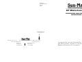
1
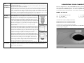
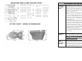
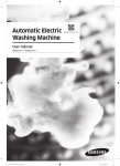
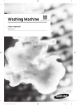
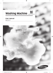
CTO-00001
SM A/F Waterless Kit
Aug 2011
Rev.D2
AF Waterless Kit
CONVERSION AND INSTALLATION
INSTRUCTIONS
Tools Required
Product Info: (905) 332-1314
Fax: (905) 332-1315
E-mail: [email protected]
600 Main St.
Tonawanda, N.Y.
14150-0888 U.S.A.
Tech. Service: (888) 341-0782 Ext 218
http://www.sun-mar.com
5370 South Service Rd.
Burlington, ON
L7L 5L1 CANADA
Kit required for use with SUN-MAR Dry Toilet and CENTREX 2000
and 3000 systems. Includes 12 volt fan and hardware kit.
Replaces all previous AF unit options.
If more thanone extension pipe piece is needed to connect the composting unit to the SUN-MAR Dry Toilet
Installing the
then
it may be necessary to vent the SUN-MAR Dry Toilet separately.
Optional Vent
on the AF “Dry
i) Obtain sufficient pipe and fittings for the vent using either 3”(75mm)
Toilet:”
sewer pipe or plumbing pipe.
ii) Trace the outside outline of the pipe on the circular section at the top
rear of the toilet top. (See Fig. A)
iii) Cut out the hole by first drilling a hole in the circumference of the traced
outline, and then carefully using a jig saw to complete the circle. Use
coarse sand paper to enlarge or smooth off the edges if necessary.
iv) Cut a short length of 3” pipe and glue it into a 3” pipe coupling , with
1/2” (13mm) of 3” pipe protruding from the 3” coupling (Fig. B).
Fig. A
Place this assembly into the hole the was created to accept the vent
stack.
v) Erect the vent stack as vertically as possible following the same rules
as outlined in the manual..
vi) If it is not possible to make this vent vertical or close to vertical, a 12
Volt fan may also have to be installed in this vent stack. Since the 12
Volt fan comes in a 12”(300mm) length of 4”(100mm) sewer pipe,
two 3” - 4” transition couplings will be required.
Fig. B
Cutting Holes
in the Toilet
Chute
Remove the bowl liner in the toilet top, and drill out a large number (15-20)
holes 1/4”(6mm) or bigger at the top rear of the chute piece no more than
3”(75mm) down from the top edge. (See Fig. C)
These holes will enable the vent on the top of the toilet to draw air out of
the toilet.
Fig. C
- 5 -
Assembling Each extension pipe piece, which comes in two pieces. These can be cut to the correct length, by cutting the required amount off the straight ends of each half with a hack saw (do not cut the belled end
and
of
Installing the the extension pipe piece.
It is easier to cut pipe sections to length before joining the two halves together. After cutting, clean up
Extension
Pipe Pieces the edges with coarse (40-60 grit) sandpaper.
Before joining the two halves of the pipe pieces, spread a bead of silicone caulking from top to bottom
along the inside flanges of both halves of pipe pieces (so that the inside of the pipe section will be
sealed). Press the two halves together, and secure them by screwing the self tapping screws provided
into the pre-drilled holes. Run a finger or spatula up along each joint inside the chute to remove any
excess silicone. Insert the non-belled end of the extension pipe piece into the transition piece. Ensure
that the transition piece overlaps the extension pipe piece by 1 -2 “ (25 - 50 mm).
Finishing the
AF “Dry
Toilet”
Installation
Pre Assembly Check: Before finishing the installation, make sure all pieces fit
together properly. The top of the pipe piece is belled out to accommodate the
toilet chute. Place the transition piece in the cut out provided on the top of
the composting unit. Place the pipe pieces, if any, inside the transition piece.
Next lower the toilet top onto the base so that the chute projects 1-2”(2550mm) into the pipe piece or directly into the transition piece if no pipe piece
is used. Ensure that the toilet top is properly located over the toilet base, that
the chute is completely vertical, and that the screws to attach the top to the
toilet base, line up properly. ( Fig. A) If the pre-assembly check appears OK, Fig. A
then disassemble and reassemble each piece as in the pre-assembly
check(see above).
To assemble the toilet top with the chute, line up top with the chute and fasten
the four screws around toilet opening and cover with the tap caps (Fig B).
Insert the toilet chute into the toilet base until the toilet top rests on the base
(Fig C). When reassembling use silicone caulking at the joints where the toilet
chute sits inside the extension pipe piece, where the extension pipe piece sits
inside the transition piece and where the transition piece sits inside the com- Fig. B
posing unit. Use a finger or spatula to remove any excess silicone.
Align the two pre-drilled holes on the front of the toilet top, with the holes on
the front of the toilet base, and insert two screws without tightening them.
With these front two holes secured, tilt the rear of the top down over the base.
Align the last four screws holes. Insert the CKS washers over the screws.
Screw in all six screws, making sure not to over-tighten, and push the snap
caps over the screw heads. Attach the toilet seat by threading the nylon
screws through the toilet seat hinge and into the holes into the toilet top. Put Fig. C
the black removable bowl liner into place under the toilet seat.
CONVERTING YOUR COMPOSTING UNIT
This kit is designed for use with the SUN-MAR Dry Toilet to convert the CENTREX 2000 and 3000 systems where little or no liquid output is desired. The CENTREX 2000 or 3000 system must be installed
directly below the SUN-MAR dry toilet. The drain is required on the non-electric units since evaporation
is not assisted by the heating element, there may be overflow liquid.
PARTS IN THE KIT
1 X AF extension pipe piece 45”
2 X 4” 45° elbow
1 X 80ml. silicone tube
1 X 12 volt 2.4 watt fan
1 X 3” air intake plug
12 X 8 ¾” truss screws
**You will also require a phillips screwdriver
REMOVE THE AF COVER PLATE
1. Remove the 6 screws on the AF cover plate.
2. Locate the composting unit directly below where the SUN-MAR Dry Toilet will be installed.
3. Removing AF coverplate.
Adjusting the The composting unit has a 3”(75mm) air intake vent at the rear of the unit. A 3”(75mm) intake cover
is supplied with this kit. Remove the 3” air intake vent and replaced with the 3”(75mm) intake cover.
Air Intake
Inserting the 3” intake cover will result in more air to be drawn down SUN-MAR Dry Toilet chute so
there is no odor in the bathroom.
- 4 -
- 1 -
EXPLOSION VIEW & PARTS FOR DRY TOILET
1
PP-TOILS-0208CX Toilet Seat White
6
PP-TOILS-0208DX Toilet Seat Bone
PM-SCRE0-0251BX
INSTALLING THE SUN-MAR DRY TOILET
#8 X 1/2” (16mm)
Stainless
2
PF-BOWLL-0246FX AF Bowl Liner
3
PP-CAP00-0587XX Tap Cap Bone
7
PP-WASH0-0274XX
CKS Plastic Washer
PP-CAP00-0587WX Tap Cap White
8
PP-SNAPC-0273XX
Snap Cap (Bone)
PP-SNAPC-0273WX
Snap Cap (White)
PP-AIRFL-003XX
Toilet Chute
PF-AIRFL-0002BX
Toilet Base Bone
PF-AIRFL-0002XX
Toilet Base White
4
Steel Flat Head Screw
PM-SCRE0-0250XX #8 X 3/4”
(19mm) Flat Head 9
Philips Screw
5
PF-AIRFL-0001BX
Toilet Top Bone
PF-AIRFL-0001XX
Toilet Top White
10
Installing the
SUN-MAR
Dry Toilet
Base
AF “DRY TOILET” ROUGH IN DIMENSIONS
The SUN-MAR Dry Toilet comes preassembled. For the purpose of
explanation, the toilet base is the bottom of the toilet which is
secured to the bathroom floor, the toilet chute is the black inner section (shown in Fig. A) that fits through the floor and is attached to the
toilet top, the toilet top is the upper part of the toilet that attaches to
the toilet base, and the bowl liner which is the black removable funnel
Fig. A
shaped piece below the toilet seat.
To install the SUN-MAR Dry Toilet, follow the procedure outlined
below:
1. To locate the position of the SUN-MAR Dry Toilet, place the toilet
chute in the desired location on the floor in the bathroom and
trace the 10”(250mm) diameter cut out in the bottom of the
toilet base on the floor in the bathroom. The centre of the 10”
Fig. B
circle should be 13” from the wall against which the toilet will be
mounted(See Fig. A)
2. Drill a 1/2”(6mm) hole on the front of traced line and then check
under the floor that the hole will be clear of floor joists and will
line up with the composting unit below. (See Fig. B)
3. If the position is correct, complete the cutting of the10”(250mm)
diameter circle with a jig saw. (See Fig. C)
Fig. C
4. Center the toilet base over the 10”(250mm) diameter hole that
has been cut out of the floor and securely attach to the floor by
using the four 5/16” by 2 1/2”(8mm by 64mm) lag bolts that are
provided with your kit. (See Fig. D)
**Prior to finishing theSUN-Mar Dry Ttoilet installation, it is a good
idea at this time to do a pre-assembly check to see if you will need
any extension pipe
Fig. D
- 2 -
The
Transition
Piece
Place transition piece(Fig. E) into the rectangular opening on
the top of the composting unit. Make sure that the transition
piece is completely vertical on the unit, or completely vertical.
Determining
if an
Extension
Pipe Piece is
Needed
Place the toilet chute into the toilet base in the bathroom. If the toilet chute extends 1-2”(25
- 50mm) into the transition piece, then no extension pipe pieces will be required. If the
transition piece does not extend far enough up to meet the toilet chute, then one or more
extension pipe pieces will be needed. These minimum 41”(112cm) pipe sections can be cut
down to the correct length, so that when assembled and placed in the transition piece, they
extend 1-2”(25-50mm) into the toilet chute. After taking into account the overlap, each pipe
piece provides an extension of about 41”(104cm).
Important: the transition piece should be completely vertical.
The opening in the toilet in bathroom should be oriented above
the opening in the transition piece so that waste can drop
Fig. E
directly into the patented bio-drum.
- 3 -