1
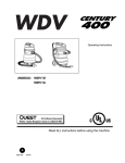
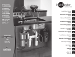
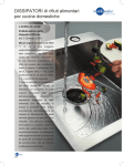
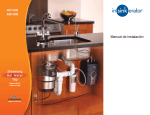
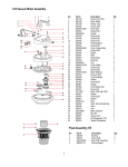
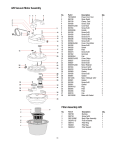
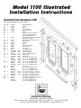
Illustrated Parts Breakdown (IPB)
(For shower head nozzle on right)
No.
#1
#2
#3L
#3R
#4
#5
#6
Qty
1
1
1
1
1
1
1
#7
2
#8
#9
#10
#11
#12
#13
#14
#15
#16
2
2
2
4
4
1
1
2
1
#17
#18
4
2
#19
2
#20
4
#21
#22
6
8
#23
2
#24
#25
#26
2
1
1
Part #
A7406
A7420
A7460
A7460
G1110
A7436
A7437
A7456
A7446
W8120
J3000
G2090
A6075
A7416
G3070GY Gray
G3070GD Gold
S82010 Zinc
G212OGD Gold
G212OGY Gray
S82070 Gold
S82075 Silver
S82075W White
S82060 Gold
S82065 Silver
S82065W White
S0170
S81060 S81065
S81065W
S83120 Gold
S83125 Silver
S83125W White
S81006
HO750
S81025
S81020
S81025W
Part Description
Header
Curb
Left Wall Jamb
Right Wall Jamb
Guide
Outside Framed Door Panel
21
Inside Framed Door Panel
with Integrated Handles
Side Rail with Integrated Handles
(Inside Door Panel)
Side Rail (Outside Door Panel)
Bottom Rail
Top Rail
Roller
Wall Jamb Bumper
21
Panel Locator
Towel Bar
Towel Bar Bracket
Panel Glide Strip
Panel Glide Strip
#8-32 x 3/8″ HWH Screw
Glazing Vinyl
Glazing Vinyl
#8 x 1-1/2″ FH SMS Screw #8 x 1-1/2″ FH SMS Screw
#8 x 1-1/2″ FH SMS Screw
21
#8 x 1-1/2″ PH SMS Screw
#8 x 1-1/2″ PH SMS Screw
3
#8 x 1-1/2″ PH SMS Screw
Screw Anchor
#6 x 1-1/2″ PH SMS Screw
#6 x 1-1/2″ PH SMS Screw
#6 x 1-1/2″ PH SMS Screw
#8 x 3/8″ FH T/S Type F Screw
#8 x 3/8″ FH T/S Type F Screw
#8 x 3/8″ FH T/S Type F Screw
#6 x 5/16″ FH Type F Screw
Optional Door Handle (see Page 8)
#6 x 3/8″ PH SMS Screw
#6 x 3/8″ PH SMS Screw
#6 x 3/8″ PH SMS Screw
12
20
8
10
17
22
1
11
17
8 22 7
19
24
11
23
10
22
15 22
18
5
17
24
12
18
14
20
22
20 12
21
23
15
22
3
7
6
26
9
22
25
19
22
21
4
2
9
16
20 12
13
21
Contractors Wardrobe
®
DESIGNERS • MANUFACTURERS
26121 Avenue Hall • Valencia, CA 91355 • (661) 257-1177 • Fax: (661) 257-4907
Toll Free: (800) CW-DOORS • (800) 293-6677 • www.CwDoor.com
In this instruction booklet we will walk you through the
installation of your new shower door.
(#3)
2 Wall Jambs - (Marked “L” and “R”)
(#4)
1 Guide
DO NOT REMOVE your old shower door until you check
that your new shower door kit is the right size for your
shower and that all the proper parts are in the box or
hardware bag. NOTE: The Header (#1) and Curb (#2) are
shipped 1” oversize, so you will need to cut each to fit.
(#5)
1 Outside Framed Door Panel
(#6)
1 Inside Framed Door Panel
with Integrated Handles
(#11) 4 Roller
Use a level to check that the tub (sill/shower dam) is reasonably level — not more than 1/4” out of level from side
to side. If it is out of level more than that, you may want
to consider ordering a custom-mitered fill that fits under
the Curb (#2). This will level the Curb (#2) correctly. In
the absence of leveling the Curb (#2) with a mitered fill,
and depending upon how badly your tub is out of level,
the panels may not stay in a closed position. Instead, the
panels may roll downhill, causing one of the doors to open.
(#12) 4 Wall Jamb Bumper
(#13) 1 Panel Locator
(#14) 1 Towel Bar
(#15) 2 Towel Bar Bracket
(#16) 1 Panel Glide Strip
(Pre-installed in Curb)
Make sure that you have all the proper tools required to
assemble your new shower door. Use this check list.
(#17) 4 #8-32 x 3/8” HWH Screw
• Phillips Head Screwdriver
• Level
• Electric Drill
• 1/8” Drill Bit (for fiberglass stall)
• 3/16” Masonry Drill Bit (for tile stall)
• Pencil
• Hammer
• Fine File
• Miter Box and Hacksaw with 32 Teeth/Inch Blade
• Caulking Gun and one Tube of Clear Tub/Tile Silicone
• 1/4” Open End Wrench
• Wire Cutters
• Tape Measure
• Duct Tape
• Safety Glasses
• Safety Gloves
(#19) 2 #8 x 1-1/2” FH SMS Screw
(#20) 4 #8 x 1-1/2” PH SMS Screw
(#21) 6 Screw Anchor
(#23) 2 #8 x 3/8” FH T/S Type F Screw
(#24) 2 #6 x 5/16" PH FT SMS Screw
If you find that any parts are damaged or missing,
refer to the parts list and IPB Drawing and contact
Contractors Wardrobe®’s Customer Service Department
at 661-257-1177. NOTE: Views and directions given in
these instructions — left, right, front, back, etc. — are
from outside the enclosure, facing the shower.
CAUTION: Wear Safety Glasses whenever drilling or
cutting. Handle the framed glass Panels carefully. The
sharp corners of the Panels can damage tile and floor
covering. Tempered glass cannot be cut. Do NOT let
the corners of the Door Panels strike the other glass
Door Panel or any hard surface, wall or floor. Even
tempered glass may be shattered in this manner.
STEP 2
DO NOT use a razor blade to cut open the paper
wrapping as you may scratch the contents. In the box or
small hardware parts bag you should find the following:
STEP 3
(#2)
1 Curb (approximately 1”oversized)
#1100 - I01100 - 0614
Installing the Curb
NOTE: If your shower has a curve (radius) in the
corners at the side walls, be sure to measure
from wall to wall below the curves.
No. Qty. Description
1 Header - (approximately 1” oversized)
Removing Existing Shower Doors
After determining that your newly purchased shower
enclosure kit is the correct size, remove the existing shower
door and all existing parts of that door assembly. Remove
all screw anchors from the wall. Clean silicone sealant
or shower caulking and any other contaminants from
shower and wall surfaces.
STEP 1
Checking Contents of Shower
Door Package
(#1)
2
A. Using the Tape Measure, measure between right and
left walls along the flattest part of the tub sill. Write
this dimension down.
B. Center the Curb (#2) on the sill/dam. In some
installations, you may prefer to position the Curb
(#2) forward or back of center. For example, by
moving the Curb (#2) forward, you will slightly
increase the depth within the shower area (See
Figure 2).
Duct Tape
STEP 4 NOTE: The Model #1100 comes with two Wall Jambs
(#3). One is notched for the left wall, the other is
notched for the right wall (as you face the enclosure from the outside). If you look at the bottom
end of each Wall Jamb (#3), on the back surface
you will see that each is clearly stamped “L” for
left, “R” for right.
INSIDE
TUB
Curb
OUTSIDE
TUB
Installing the Wall Jambs
Top of
Wall Jamb
Level
Silicone
Panel Glide Strip
Figure 2
C. Locate Curb (#2). Remove the Panel Glide Strip
(#16) from the Curb (#2). See IPB Drawing.
D. Using the measurement from Step 3A, cut the
Curb (#2) to this length. Use the Miter Box and
Hacksaw to make a straight cut.
If your enclosure has
rounded corners,
use a file to shape the
Curb to fit
Curb
Figure 3
E. Using the Wire Cutters, cut the Panel Glide Strip
(#16) 3/8” shorter than the Curb (#2). Re-install
the Panel Glide Strip (#16) into the Curb (#2)
and position it (center it) so that the ends of
Panel Glide Strip (#16) are evenly spaced at
each end of the Curb (#2).
F. Cut two pieces of Duct Tape 12” long. Next,
use the Caulking Gun to apply a thick bead of
Silicone sealant (approximately 3/8” in diameter)
to the bottom surface of the Curb (#2) along its
entire length. Place the Curb (#2) on the shower
sill, in the position you determined in Step 3B.
Use the two strips of Duct Tape to temporarily
hold the Curb (#2) in place, but DO NOT place
the tape within 2” of the wall. In other words, the
distance (gap) between the wall and the tape
should be 2” or more away from the walls so that
the tape will not be in your way when you install
the Wall Jambs (#3) (See Figure 2).
A. Locate the left Wall Jamb (#3L) marked with an
“L”. If your shower has curved corners, use a
File to round off and shape the bottom ends of the
Wall Jambs (#3) to fit the rounded corners of the
shower.
B. Place the left Wall Jamb (#3L) against the left wall
and slip/snap the bottom of the Wall Jamb (#3L)
over the Curb (#2). Use a Level held against the
side of the Wall Jamb (#3L) to align it vertically
straight up and down as shown in Figure 3. Use
a Pencil to mark the position of each of the three
12
20
Shower head
and controls
right side
3L
19
NOTE: The tape will help provide a positive seal to the
shower sill while holding the Curb (#2) in place for
the following steps.
12
20 12
19
20
3R
20 12
13
3
Figure 4A
#1100 - I01100 - 0614
12
20
STEP 5 Shower head
and controls
left side
A. In order to install the Panel Locator (#13) you
must first determine which wall the shower head
is on. See Figures 4A and 4B.
3L
19
13 12
20 12
B. Attach Panel Locator (#13) to the edge of the
Wall Jamb (#3) on the shower head side, as
shown.
STEP 6 19
20
20 12
B. Locate the Header (#1). Using the Miter Box and
Hacksaw, cut the Header (#1) to the length you
just measured.
Figure 4B
pre-drilled holes in the left Wall Jamb (#3L). Set
the Wall Jamb (#3L) aside for the moment.
C. Using either a 1/8” Drill Bit (for a fiberglass
enclosure) or a 3/16” Masonry Drill Bit (for tile) drill
three holes where you made
the marks. If installing in a
tiled enclosure, gently tap
a Screw Anchor (#21) into
each hole. DO NOT use the
Screw Anchors (#21) for a
fiberglass enclosure.
D. Place the Wall Jamb (#3L)
back over the Curb (#2) and
against the wall and secure
with a single #8 x 1-1/2” PH
SMS Screw (#20) and one
Wall Jamb Bumper (#12)
in the TOP hole only, at this
time.
C. The Model #1100 comes with a positive snap-lock
feature which eliminates the need for screws to
hold the Header (#1) in place, and help to secure
the Panels (#5 and #6) in Header (#1) in case
there is an earthquake. Position the Header (#1)
over the top of the Wall Jambs (#3). Spread the
Header (#1) sides slightly as you pull it down
firmly onto the Wall Jambs (#3) as it snaps and
locks in place. You should be able to hear and
feel when it solidly locks in place.
STEP 7 E. Repeat Steps 4A through 4C for the right Wall
Jamb (#3R).
F. Remove the Duct Tape after Silicone dries.
G. Use two #8 x 1-1/2” FH SMS Screws (#19) to
secure the middle of the Wall Jamb (#3).
H. Use two #8 x 1-1/2” PH SMS Screws (#20) to
secure the Wall Jamb Bumpers (#12) in the bottom hole of the left and right Wall Jambs (#3) to
completely secure the Wall Jambs (#3).
Installing the Rollers on
the Panels
IMPORTANT: Enclosures with Obscure or Specialty
glass are installed with the textured surface of the framed
Panels facing out, or to the front. The smooth surface will
face into the shower. This orientation gives you the front
and back of each Panel. Now, locate the Outside Framed
Door Panel (#5). Locate four #8-32 x 3/8” HWH Screws
(#17).
Figure 4C
#1100 - I01100 - 0614
Installing the Header
A. Using the Tape Measure, measure the distance
between the left and right wall at the top
(Remember, the width at the bottom of the
enclosure may not be the same as the width of
the top of the enclosure because walls may not
be plumb and square).
3R
Installing the Panel Locator
4
A. Use two #8-32 x 3/8” HWH Screws (#17) to attach
two Rollers (#11) to the top of the Outside Framed
Door Panel (#5) with the Rollers (#11) on the
front surface of the Top Rail (#10). The metal
parts (the Nut side) should be against the frame,
as shown in Figure 5B.
D. If someone is assisting you, First Panel Installation
(Inside Door)
have he or she stand in the
shower and pull the bottom
edge of the Inside Framed
Door Panel (#6) towards
them, to give you about 2” of
clearance for the next step.
Inside
A
If you are installing the doors
Shower
by yourself, you will need to
push the Inside Framed Door
Panel (#6) out of your way
A
as we describe here. Hold Outside
A
the Outside Framed Door Shower
Panel (#5) so that the Rollers
Figure 6A
(#11) face towards you. Lift
the Outside Framed Door
Second Panel
Panel (#5) and use the index
Installation
finger of both hands to
(Outside
Door)
carefully push the Inside
Framed Door Panel (#6) back
and out of the way as you
lift the Outside Framed Door
Panel (#5) up and over the
Curb (#2). Insert the Top Rail
Push
(#10) up and into the Header
with
(#1). Set the wheels into the
index
finger
front track of the Header (#1)
(See Figure 6B).
Outside Tub:
Front of each
panel faces out
Figure 5A
B. Use two more #8-32 x 3/8”
HWH Screws (#17) to attach
the remaining Rollers (#11) Frame
to the back surface of the Top
Top Rail (#10) of the Inside
Framed Door Panel (#6). Front of
The metal parts (the Nut side) Outside
should be against the frame, Panel
as shown in Figure 5C. (Textured
Nut
side)
Figure 5B
Outside
Panel - Rollers
on front side
Inside Panel - Rollers
on back side
Inside
Tub:
Smooth
side of
glass
E. VERY CAREFULLY set
the Outside Framed Door
Panel (#5) into the track
and make sure that it rolls
freely. Carefully ease the
Inside Framed Door Panel
(#6) back into place.
Figure 5C
STEP 8
Installing the Door Panels
Installing the Door Panels may be easier if you have
someone assisting you. Always wear gloves and safety
goggles whenever handling glass.
STEP 9 A. Locate the Inside Framed Door Panel with
Integrated Handles (#6). When standing inside
the shower, the curved Integrated Handles will be
facing you.
B. Hold the Inside Framed Door Panel (#6) so that
the rollers are facing away from you. Standing
outside and facing the shower enclosure, lift the
Inside Framed Door Panel (#6) up and over the
Curb (#2) and then lift the Top Rail (#10) up into
the Header (#1) (See Figure 6A).
C. Gently set (lower) the Inside Framed Door Panel
(#6) into position with the wheels seated in the
rear track of the Header (#1). Make sure that the
Panel rolls freely.
5
F. Slide both Panels to one side
to prepare for the next step.
Tub Sill /
Shower Dam
Figure 6B
Adjusting and Aligning the
Door Panels
A. To ensure that the enclosure is water-tight, the
Door Panels (#5, #6) must be correctly aligned.
Slide the Inside Framed Door Panel (#6) toward
the wall with the shower head. Slide the Outside
Framed Door Panel (#5) to the opposite wall. If
the Door Panels (#5, #6) are not flush with the
Wall Jambs (#3) or are too high off the Curb
(#2), the unit could leak while the shower is
in use. If the edges of the Door Panels (#5,
#6) do not align flush with the Wall Jambs (#3),
the Door Panels (#5, #6) need to be adjusted.
B. One or more of the Rollers (#11) may need to
be adjusted to properly align the Door Panels
#1100 - I01100 - 0614
(#5, #6). Using a 1/4” Open End Wrench, loosen
the #8-32 x 3/8” HWH Screw (#17) securing the
Roller (#11) and gently slide the Roller (#11) in
either direction until the Door Panels (#5, #6) hang
flush with the Wall Jambs (#3). Tighten the screw
(See Figure 7).
Outside
Shower
Adjust
Hex Screw
Figure 7
STEP 10 Installing the Towel Bar
A. Locate the Towel Bar (#14), two Towel Bar
Brackets (#15), two #8 x 3/8” FH T/S Type F
Screws (#23) and two #6 x 5/16" FH Type F
Screws (#24).
STEP 11 B. To assemble the Towel Bar, insert the Towel
Bar Bracket (#15) into the end of the Towel Bar
(#14) as illustrated in Figure 8. Take a #6 x 5/16"
FH Type F Screw (#24) and lock the Towel Bar
Bracket (#15) into place. Repeat these steps for
the other side.
WARNING! DO NOT ATTEMPT TO LOCK THE GUIDE
(#4) IN PLACE UNTIL YOU ARE READY TO INSTALL
IT! Once the Guide (#4) is in place the shower Door
Panels will be EXTREMELY difficult to remove and
adjusting or removing the Guide (#4) will be nearly
impossible.
C. Align the Towel Bar Bracket (#15) with the
pre-drilled slot in the door Side Rail (#7) of
the Outside Framed Door Panel (#5). Use a
#8 x 3/8” FH T/S Type F Screw (#23) to secure
the Towel Bar Bracket (#15) to the door Side Rail
(#7) of the Outside Framed Door Panel (#5) (See
Figure 8). Repeat these same steps for the other
side.
A. Locate the Guide (#4). First, make sure that the
surface of the Curb (#2) is entirely clean of oil, dust,
debris or other contaminants.
Screw
(#23)
Screw
(#24)
Screw
(#24)
Towel Bar
Bracket (#15)
Towel Bar (#14)
Figure 8
#1100 - I01100 - 0614
Figure 9A
Installing the Guide
B. With a Tape Measure, measure from Wall Jamb
(#3) to Wall Jamb (#3) and, with a Pencil, mark
the center point of the Curb (#2) on the inside
edge of the Curb (#2) or lightly on the shower sill
or tile where it will be visible. Remember, you will
want to be able to see the Pencil mark after you
insert the Guide (#4) into the groove in the Curb
(#2) so that you will know where to center the
Guide (#4).
Hook in
Curb
Screw
(#23)
Don’t
Lock
Down
Figure 9B
Snap Down
When
Centered
Towel Bar
Bracket
(#15)
6
Figure 9C
STEP 13
C. Slide both Door Panels (#5 and #6) to one
side. Peel the paper backing off the two-way
tape on the bottom of the Guide (#4). Without
letting the adhesive tape touch the Curb
(#2) OR accidentally pressing down or
locking the Guide (#4) into place, carefully insert
the front edge of the Guide (#4) into the groove
in the Curb (#2) and slide the Guide (#4) under
the two Door Panels (#5 and #6) as shown in
Figure 9B. Center the Guide (#4) on the pencil
mark you made (See Figure 10).
The enclosure Door Panels (#5 and #6) are not designed
to be removed once they are installed. However,
inconvenient areas that you may want to clean, such as
the overlap between the doors, can still be reached for
cleaning.
D. Press the Guide (#4) onto the Curb (#2) and lock it
into position by pressing firmly on the back edge of
the Guide (#4) as shown in Figure 9C. You should
feel it lock into place. If the Guide (#4) doesn’t lock
into position easily, it may be necessary to press
firmly on one end to start the process and work
along the back of the Guide (#4) in order to lock it
into place.
A. Carefully remove all the hardware from door. This
will enable you to slide the glass Panels (#5 and
#6) in either direction to clean the entire Panel
thoroughly.
B. Clean the glass with a mild, non-abrasive cleaner
designed for glass such as
Mirror & Glass
Cleaner.
C. Re-install the hardware when you are finished.
CAUTION: Removing one or both of the Panels (#5
and #6) should NOT be attempted without
assistance. Always wear Safety Goggles and
Gloves when handling the glass Panels (#5 and
#6). Read through the following instructions first
to familiarize yourself before proceeding.
Outside
Shower
Should it become necessary to remove one
or both of the Panels IT WILL REQUIRE TWO
PEOPLE TO DO THIS.
Inside
Shower
Figure 10
STEP 12 Cleaning and Removing the Door Panels
D. If you applied Silicone Caulking around the Header
(#1), carefully remove it by cutting through the
Silicone with a Razor Blade. Use care when
cutting through the Silicone so that you do not
scratch or mar the extrusion.
E. Slide both Panels (#5 and #6) to one side. Now
you need to release the Header (#1) from the Wall
Jamb (#3). At the opposite side (from the Panels),
loosen the Header (#1) from the Wall Jamb (#3).
Spread the Header (#1) open to release it from
the locking grooves on the Wall Jamb (#3) and,
at the same time, lifting it slightly in the air. When
the Header (#1) is free, set it back on top of the
Wall Jamb (#3).
F. Now carefully slide both Panels (#5 and #6)
toward the end you have released from the Wall
Jamb (#3) and have the second person hold the
Panels (#5 and #6) in place while you repeat Step
13-E to release the other side of the Header (#1)
from the Wall Jamb (#3).
Silicone Sealing the Enclosure
Using rubbing alcohol and a lint-free rag, thoroughly clean
the edges of the aluminum enclosure and tiles and at
both ends of the Header (#1) at the walls, where the Wall
Jambs (#3) meet the tile or fiberglass surfaces and along
all edges of the Curb (#2) and sill/dam. When the alcohol
has dried, you will have a clean, excellent surface for
silicone sealing the enclosure. Use the Caulking Gun with
clear Tub/Tile Silicone to seal both ends of the Curb (#2)
where it meets the Wall Jambs (#3), along both the interior and exterior edges (horizontal and vertical) and
along the interior edges where the Wall Jambs (#3) and
Curb (#2) meet with the tile or fiberglass surfaces. It is not
necessary to silicone around the Header (#1).
NOTE: Silicone sealant must cure for 24 hours before
you use your new enclosure. Silicones may vary.
Please follow curing instructions on the tube.
7
#1100 - I01100 - 0614
Optional Door Handle
G. With the Header (#1) free from both Wall Jambs
(#3) and the Panels (#5 and #6) hanging in the
Header (#1), you should now be able to lift out
one or both Panels (#5 and #6) from the Guide
(#4) and disengage them from the Header (#1).
Installing the Optional Door Handle
Please note that the Door Handle (#25) is not necessary.
This can be used as another handle to enter the
enclosure. Once installed the Door Panels will not
bi-pass one another.
H. As an alternative to taking out one Panel at a time
and having to remove the hardware from each
Panel, you might try this: With the Header (#1)
free from both Wall Jambs (#3), slide the Panels
(#5 and #6) to the center. Each person holds the
Header with one hand next to the Panels (#5 and
#6) to keep them from sliding and the other hand
at the end of the Header (#1).
I. With the Panels (#5 and #6) secured so they
won’t slide, lift the Header (#1) with hanging
Panels (#5 and #6) up and out of the shower
enclosure. Carefully lay the Panels (#5 and #6)
on the floor while still in the Header (#1).
J. To re-install the Door Panels (#5 and #6), reverse
the process described above, hanging the Panels
(#5 and #6) in the Header (#1) and re-attach the
Header (#1) onto the Wall Jambs (#3).
Handle
(#25)
Inside of
Shower
Screw
(#26)
Position Handle
midway on Door Panel
A. Locate the Handle (#25) and the #6 x 3/8″
Screw (#26).
B. Standing on the outside of the enclosure, with
the curved part of the Handle (#25) facing towards
you, position the Handle (#25) midway on the
frame of the Inside Framed Door Panel (#6) (as
measured from the bottom of the Panel), on the
edge nearest the Wall Jamb (#3) near the shower
head. Use a #6 x 3/8″ Screw (#26) to attach the
Handle (#25) to the Side Rail (#7) of the Inside
Framed Door Panel (#6).
WARNING
Make sure not to drill into the Side Rail (#7) before
attaching the screw. Drilling directly into the Side Rail
(#7) could potentially cause the glass Panel to explode.
The screw will safely drill through the Handle (#25) and
into the Side Rail (#7).
Thank you for purchasing a
Shower Enclosure. If
you like this product, we invite you to visit our website at
www.CwDoor.com for more information about our
extensive line of other Shower Enclosures, Room
Partitions and Loft Dividers, Cabinet Doors, and
Wardrobe Doors. They feature Duratuf ® Tempered
Safety Glass, Painted Glass, CwShield™ Protective
Coating and Duraflect ® Copper-Free Mirror.
#1100 - I01100 - 0614
8