1
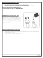
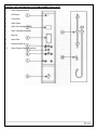
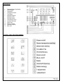
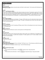
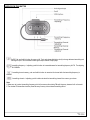
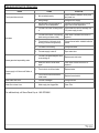
Royal Luxury Series Installation & Operations Manual WS-102 WS-105 Note: You must read all installation & operation instructions prior to assembly and use of this unit. 1|Page Rev 10/2012 Table of Contents Notice to Installers Tools Needed for Installation Product Features Unit Information Electrical Information Plumbing Requirements General Information Installation Instructions for WS102 & WS105 Cleaning & Maintenance Steam Generator Cleaning General use & Maintenance Control Parts Information LCD Display Information Control Panel Information Control Procedures Wireless FM Transmitter Information Troubleshooting ……………………………………………. ……………………………………………. ……………………………………………. ……………………………………………. ……………………………………………. ……………………………………………. ……………………………………………. ……………………………………………. ……………………………………………. ……………………………………………. ……………………………………………. ……………………………………………. ……………………………………………. ……………………………………………. ……………………………………………. ……………………………………………. ……………………………………………. 3 3 4 4 5 5 5 6-7 8 8 8 9 10 10 11-12 13 14 Thank you for selecting Steam Planet Corp Computerized Steam Rooms. In order to operate and use the product properly, please follow all instructions provided in this User’s Manual. Our company reserves the right to change the Manual at anytime. The manual takes effect the date it is published. This manual shall prevail if there is any difference between this and previous documents and manuals. 2|Page Rev 10/2012 NOTICE TO INSTALLERS (if applicable) THE FLEXIBLE DRAIN HOSE THAT IS INCLUDED WITH THIS UNIT IS FOR INSTALLATION INTO AN OPEN FLOOR DRAIN ONLY. SUBSTITUTING THE EXISTING DRAIN SHOE FOR A DIFFERENT ONE WILL NOT VOID THE WARRANTY AS LONG AS THERE NO DAMAGE OR EVIDENCE OF MISUSE TO THE BASE. IF A DIFFERENT DRAIN SYSTEM FOR THE SHOWER IS USED, THE STEAM GENERATOR MUST A HAVE DRAIN CONNECTION AVAILABLE TO DISCHARGE THE WATER INTO THE MAIN SHOWER DRAIN. A 3/8”OD STUB MUST BE ADDED TO THE MAIN SHOWER DRAIN TO CONNECT THE STEAM GENERATOR DRAIN OUTLET. Note: Within the Warranty period, please don’t take off the decals from the computer control boxes and the steam generator without manufacturer’s permission. Have only licensed professionals install or perform any maintenance. Generally, our technicians can troubleshoot most problems over the phone. When calling for service questions, please provide your model number, serial number, Purchase Order, and type of problem you are having. TOOLS REQUIRED FOR INSTALLATION: Level Screw driver #2 Phillips Silicone Wrench Electric Drill Square Ruler Rubber mallet 3|Page Rev 10/2012 PRODUCT FEATURES DESCRIPTION WS102 WS105 4.2kW Quick heating -Self-Draining Steam Generator 3kW Quick heating -Self-Draining Steam Generator Steam Aromatherapy Cup Body Massage Jets Hand-held Shower w/ Various water massage settings & adjustable height bracket 8 inch (203mm) wide water-drenching Rainfall Shower Thermostatic / Anti-scald Faucet Strengthened Black Back Tempered Glass walls Clear Glass Front & Doors Polished Aluminum Trim “Glass Touch”/no seam Control Panel Complete media center with FM Radio Wireless transmitter for all devices “Chromatherapy” LED multiple Color Lighting Waterproof Oak Shower floor Grid Accessory Rack Circulation Fan Corner Unit Folding Seat Removable Wood Stool Sliding doors Swinging Door UNIT INFORMATION Model WS102 WS105 . Electric Parameter Voltage Power Frequency 220V 3KW 60-50Hz 220V 4.2KW 60-50Hz Length 1016mm/40 Inch 1200mm/48 Inch Size Width 1016mm/40 Inch 1200mm/48 Inch Height 2250mm/88.5 Inch 2250mm/88.5 Inch Steam Ready: 1-2 minutes, optimum room temperature reached within 2-5 MIN. 4|Page Rev 10/2012 ELECTRICAL INFORMATION 1 dedicated 12-2 wire with 20 amp GFCI breaker (220V) Connect the overhead light, speaker, fan, CD, telephone according to the tags on the wires. Do not connect the wire “O3” to anything. Connect main power supply. PLUMBING INFORMATION The unit is equipped with 3 ft. hot and cold, metal braided water supply hose with ½-inch national pipe thread to connect from faucet/manifold (Manifold is located. 4 ft. high on rear of unit) to the shutoff valves (should be installed where they can be accessed). Note: base edge sets directly against back and sidewall. Do not install any pipes along walls as to impede the base from setting flush against them.. Install hot and cold shutoffs with ½ -inch male national pipe thread (not included). Install shutoffs where they can be accessible. Access panel near controls, pumps, and jets is recommended Drainage: It is advised to have base onsite before preparing drain location. The diameter of the drain hole should be larger or equal to Φ40mm (1.6 inches). Note: The flexible drain hose included with this unit is for installation into a floor drain only. Substituting the existing drain setup for a setup of the installers’ choice will not void the warranty of the unit as long as there is no evidence of misuse or damage to the base. If the substitute drain system is used, a 3/8 in stub must be added to the main shower drain line to connect the steam generator’s automatic flushing drainage hose. All fixtures and fittings must be checked for tightness as they may have been loosened during transport GENERAL INFORMATION Connect hot and cold supplies and all electrical just before unit is set into place. Units come broken down in panels and are assembled with screws, nuts and bolts on site. Note: All shower bases need to be leveled in its final resting position (all feet must be touching the ground), mark the placement, then pull base out and begin assembly. It is advised to have base onsite before preparing drain location. Access panel near controls panel and jets recommended. Manufacturer reserves the right to change specs or features at anytime. Please check to confirm details. 1-866-783-2661 5|Page Rev 10/2012 INSTALLATION INSTRUCTIONS FOR WS102 & WS105 1. Level the tray with the level. 9. Inspect and tighten the body jets and hoses if necessary 2. Make sure all the adjustable feet are touching the ground and supporting the base. 10. Install the left and right side black back walls. 3. Connect the drain if building the unit in its final resting place. Note: This unit can be built from the inside. 4. Assemble curved, horizontal rail to left and right vertical rails using ST4X40 screws. 11. Install the left and right clear fixed panels. 5. Attach the door frame to the base using ST4X40 screws. 12. Bring main center panel inside the unit. 6. Use ST4X20 screws and covers to attach the vertical rails to the base skirt. 7. Attach the chrome trim to the base. 8. Install the shower bar on the right side back panel using hardware enclosed in cloth bag. Install shampoo holder onto the left black back panel using M4X25 caps, nuts, bolts, and O-rings 13. Connect water supply lines to the water manifold. Connect side panel water jets to the manifold, then connect the power supply. 14. Attach center panel to right and left side panels with ST4X16 screws. 6|Page Rev 10/2012 INSTALLATION INSTRUCTIONS FOR WS102 & WS105 18. Reinstall the aluminum strips near the back panel. 15. Connect fan, light, and radio wires to the roof. Install the roof of the shower cabin using ST4X12 screws 16. Install the sliding doors. Spring loaded rollers go on the bottom. 19. Adjust the sliding doors so that they close tightly. 20. Attach the door gaskets. 17. Install the door handles. 21. Lastly, place the wooden floor grids on the shower tray and place stools (WS-105 only) on the inside of the unit. 22. Install the shower wand and flexible hose and place inside sliding shower rail. 7|Page Rev 10/2012 CLEANING AND MAINTENANCE FOR ALL UNITS 1. Liquid detergents and soft cloth should be used. Do not use any abrasive cleaners. 2. The scale on the surface can be cleaned with a soft cloth and non abrasive cleaner or heated vinegar. 3. After every 30 times of using the unit, we suggest you to clean the steam generator. We advise the use a filtration system for the steam generator unit. One Compatible filtration system option is the -Whirlpool WHKF-DWHV STEAM GENERATOR CLEANING FOR ALL UNITS Remove the cover of the cleaning liquid inlet and pour in approximately 1L of citric acid or white vinegar. Start the steam function to fill the steam generator with water. Stop the steam function before the steam starts to come out (“acidic” steam is damaging to plated fixtures). Do not shut off the main power. The scale in the steam generator dissolves and the system drains the dirty water out after 60 minutes. GENERAL USE AND MAINTENANCE FOR ALL UNITS A. Drops of water will continue to drain out from the jets and water outlets after use, this is normal and it will eventually stop. B. Abrasive cleaners must not be used. C. Always shut off the power supply when the system is not in use. 8|Page Rev 10/2012 CONTROL PARTS INFORMATION FOR STEAM SHOWER FOR ALL UNITS 1. Steam Temperature Sensor 2. LCD Display 3. Control Panel 4. Water Diverter 5. Water Flow Adjustment (On/Off) 6. Water Temperature Adjustment 7. Body Jets 8. Steam Outlet 9. Handheld Shower Set 10. Steam Generator Cleaning Liquid Inlet 9|Page Rev 10/2012 LCD DISPLAY: 1. 2. 3. 4. 5. 6. 7. 8. 9. 10. 11. 12. 13. 14. Fahrenheit Degree (if applicable) Celsius Degree Temperature Temperature Indicator Time Setting FM Radio Frequency FM Radio Volume FM Radio Channel Chromatherapy on/off Circulation Fan on/off Steam on/off Power on Indicator FM Radio Frequency Mp3 on/off CONTROL PANEL FOR STEAM SHOWER: 10 | P a g e Rev 10/2012 CONTROL PROCEDURES Power on/off Push any button to light the display, and press the power on/off switch to start the system. Push the power on/off switch again to turn off the system and display. Steam Temperature Setting Touch the Steam Temperature Setting button and the display will appear on the screen. The temperature ranges from 20°C to 59°C circularly. Let go of the button when the desired temperature has been reached, and the figure is set as a steam setting. The steam generator stops working when the temperature inside is 4°C higher than setting temperature. The steam generator has 4°C variance between accrual set temperature and real temperature. The default steam setting is 45°C if the user does not choose any setting. Steam Time Setting Touch the Steam Time Setting button and the display. The range is 20-59 minutes. Let go of the button when the figure reaches the desired time and is set as the working time for the system. The system is automatically shuts off when the set time expires or 45 minutes is up (default system time). Chromatherapy This button controls the color of the Chromatherapy LED lights (picture 5). When the Chromatherapy function starts, the lamp symbol on the LCD display flashes. Circulation Fan This button turns fan on/off. When fan is turned on, the fan symbol on the LCD display Flashes. Steam on/off This button turns the steam on/off. Touching this button makes the steam symbol on the LCD display flash. The temperature sensor regulates steam output based on the preset steam temperature. The steam generator has 4°C variance between accrual set temperature and real temperature. Music on/off This button turns music on/off. FM Radio on/off Touch this button, and the radio station will show on the display. The FM radio is now on. The radio frequency by default is the same as the radio frequency selected last time. Note: if the MP3 shows on the display the radio will not play. Touch the FM radio button again. Volume & Frequency Adjust Volume Touch this button when the FM radio is on. Push Frequency Touch this button when the FM radio is on. Push the [ to adjust the volume. Display will show DB. again to adjust the frequency. Display will show MHZ. 11 | P a g e Rev 10/2012 Channel Memory Channel Memory Setting: o Start FM Radio o Set serial number touch button and touch this button when the wanted fissure shows. button again, fissure from 1 to 8 shows circularly; stop touching o Adjust FM Radio to your favorite channel; touch button to adjust frequency and volume. Channel Memory: Touch button for more than 3 seconds; the figure shows +1 and turns to original setting station number. Release button to finish setting for one channel. If the station number is used for another channel, this channel will be replaced by the new channel in memory. o Repeat the above steps to save channels in memory. Maximum 8 channels can be memorized. Find Channel: o o o Start FM Radio. Touch button to find right channel in memory. + adjust - adjust The above 2 buttons are used to adjust frequency and volume. 12 | P a g e Rev 10/2012 WIRELESS FM TRANSMITTER On/Off: Push and hold this button for power on/off. Push and release this button shortly to change between transmitting and clock. Audio signal input: to be connected to audio signal output interface of Mp3 player. Transmitting frequency +/- adjusting: push this button to increase/decrease for transmitting frequency for FM. The adjusting range is 88-108.8MHz. Transmitting channel memory: push and hold this button to memorize this channel after the transmitting frequency is selected Transmitting channel +/- adjusting: push this button to select the transmitting channel from memory up or down. Note: 1. Make sure not to select transmitting frequency which is the same as the existing FM radio frequency because it will not transmit. 2. The wireless FM transmitter should be placed far away from any other wireless transmitting device 13 | P a g e Rev 10/2012 TROUBLESHOOTING FOR STEAM CABIN ISSUE Touch panel does not work CAUSE 1. Not connected properly 2. Wrong voltage No steam Steam generator keeps adding water Power supply is off when on/off button is pushed SOLUTION Check connection between control panel and power box 1. Desired steam room temperature is lower than current temperature Change to 220V supply Increase the desired temperature to be higher than current temperature 2. The water inlet valve not letting water in Check water inlet valve for blockage and 12V power supply to valve 3. The water level sensor is not working (water coming out steam outlet) Clean scale of the water level sensor or replace it 4. Thermal switch in the heater is not working (no steam from generator) Change thermal switch installed inside the heater 5. The heater is not working Change the heater 6. The water supply is shut off Open water valve 1. The water inlet electromagnetic valve is not shutting off Replace water inlet valve 2. Water level sensor cannot detect signal Clean scale of water level sensor or replace it 1. There is short circuit from heater Replace heater 2. There is short from thermal switch inside heater Replace thermal switch Water leaks from valve The seal is damaged Change the seal Water flow volume is low Water supply has clogged filter. Clean Filter For additional help, call Steam Planet Corp at 1-866-STEAM-61. 14 | P a g e Rev 10/2012 15 | P a g e Rev 10/2012 16 | P a g e Rev 10/2012