1
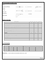
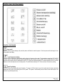
By Galaxy Series Installation & Operations Manual WS-112 Note: You must read all installation & operation instructions prior to assembly and use of this unit. 1|Page Rev1/2015 Table of Contents Tools Needed for Installation Product Features Unit Information Electrical Information Plumbing Requirements General Information Base Information Assembly & Installation Handle Assembly Temperature adjustments Diverter Maintenance & Care Cleaning & Maintenance Steam Generator Cleaning General use & Maintenance Control Parts Information LCD Display Information Control Panel Diagram Control Procedures Wireless FM Transmitter Information Troubleshooting ……………………………………………. ……………………………………………. ……………………………………………. ……………………………………………. ……………………………………………. ……………………………………………. ……………………………………………. ……………………………………………. ……………………………………………. ……………………………………………. ……………………………………………. ……………………………………………. ……………………………………………. ……………………………………………. ……………………………………………. ……………………………………………. ……………………………………………. ……………………………………………. ……………………………………………. ……………………………………………. 3 3 3 4 4 4 5 6-8 8 9 9-10 10 10 10 11 11 12 12-13 14 15 Thank you for selecting Steam Planet Corp Computerized Steam Rooms. In order to operate and use the product properly, please follow all instructions provided in this User’s Manual. Our company reserves the right to change the Manual at anytime. The manual takes effect the date it is published. This manual shall prevail if there is any difference between this and previous documents and manuals. WARNING! Note: Within the Warranty period, please don’t take off the decals from the computer control boxes and the steam generator without manufacturer’s permission. Have only licensed professionals install or perform any maintenance. Generally, our technicians can troubleshoot most problems over the phone. When calling for service questions, please provide your model number, serial number, Purchase Order, and type of problem you are having. 2|Page Rev1/2015 TOOLS REQUIRED FOR INSTALLATION: Level Screw driver #2 Phillips Silicone Wrench Electric Drill Square Ruler Rubber mallet PRODUCT FEATURES DESCRIPTION WS112(32) WS112(36) WS112(40) 4.2kW Quick heating -Self-Draining Steam Generator Steam Aromatherapy Cup Body Massage Jets Hand-held Shower w/ Various water massage settings & adjustable height bracket 8 inch (203mm) wide water-drenching Rainfall Shower Thermostatic / Anti-scald Faucet Strengthened Black Back & Side Tempered Glass walls Clear Glass Front & Doors (easily reversible) 24Inch (610mm) Swinging Door Polished Aluminum Trim “Glass Touch”/no seam Control Panel FM Radio Wireless transmitter for Radio “Chromatherapy” LED multiple Color Lighting Waterproof Oak Shower floor Grid Accessory Rack Circulation Fan Alcove Free Standing Unit Removable Wood Stools UNIT INFORMATION Model WS112(32) WS112(36) WS112(40) Voltage 220V 200V 200V Electric Parameter Power Frequency 4.2KW 60-50Hz 4.2KW 60-50Hz 4.2KW 60-50Hz Length 1500mm/59 Inch 1500mm/59 Inch 1500mm/59 Inch Size Width 813mm/32 Inch 915mm/36 Inch 1015mm/40 Inch Height 2150mm/84.5 Inch 2150mm/84.5 Inch 2150mm/84.5 Inch Steam Ready: 1-2 minutes, optimum room temperature reached within 2-5 MIN 3|Page Rev1/2015 ELECTRICAL INFORMATION 1 dedicated 12-2 wire with 20 amp GFCI breaker (220V) Connect the overhead light, speaker, fan, CD, telephone according to the tags on the wires. Do not connect the wire “O3” to anything. Connect main power supply. PLUMBING INFORMATION The unit is equipped with 3 ft. hot and cold, metal braided water supply hose with ½-inch national pipe thread to connect from faucet/manifold (Manifold is located. 4 ft. high on rear of unit) to the shutoff valves (should be installed where they can be accessed). Note: base edge sets directly against back and sidewall. Do not install any pipes along walls as to impede the base from setting flush against them.. Install hot and cold shutoffs with ½ -inch male national pipe thread (not included). Install shutoffs where they can be accessible. Access panel near controls, pumps, and jets is recommended Drainage: It is advised to have base onsite before preparing drain location. The diameter of the drain hole should be larger or equal to Φ40mm (1.6 inches). Note: The flexible drain hose included with acrylic base is for installation into a floor drain only. Substituting the this drain setup for a setup of the installers’ choice will not void the warranty of the unit as long as there is no evidence of misuse or damage to the base. If the substitute drain system is used, a 3/8 in stub must be added to the main shower drain line to connect the steam generator’s automatic flushing drainage hose. All fixtures and fittings must be checked for tightness as they may have been loosened during transport PLUMBING REQUIREMENTS The unit is equipped with hot and cold, metal braided water supply hoses with ½ national pipe threaded fitting. Need to install hot and cold shutoffs with ½ -male national pipe thread (not included). All fixtures and fittings must be checked for tightness as they may have been loosened during transport Note for Acrylic Base ONLY: The flexible drain hose included with this unit is for installation into a floor drain only. Substituting the existing drain setup for one of the installers’ choice will not void the warranty of the unit as long as there is no evidence of misuse or damage to the base. GENERAL INFORMATION The main wall panel with water manifold and electrical equipment is designed to be installed on the left side of unit. If water and electrical connections are on the right side, these side wall panels are interchangeable (please call Steam Planet Technician before this is done). This must be completed onsite by installer. Units come broken down in panels and are assembled with screws, nuts and bolts on site. All Acrylic shower bases need to be leveled in its final resting position (all feet must be touching the ground), mark the placement. All Stone shower bases may need to be set and leveled in place on a bed of thin set mortar. It is advised to have base onsite before preparing drain location. Access near controls and jets is recommended. Manufacturer reserves the right to change specs or features at anytime. Please check to confirm details. 1-866-7832661 4|Page Rev1/2015 BASE OPTIONS The standard WS-112 shower enclosure does not include a base. It can be installed over a custom or existing base of your choice. Steam Planet offers one base option: A man made “cultured stone” base (Black or White) that sets into place or may require some type of cement/thin set mortar foundation. You will find information regarding these bases below. OPTIONAL STONE BASE: Stone Base needs to be set in the final resting space and leveled. Use standard stone base installation to secure the base in place. The drain hole is 3” inches in diameter. The drain is located in the center of the base. The unit is assembled and sets entirely inside the stone base’s water edge.. NOTE: When assembling the Model WS112 to the Stone Base, disregard the instructions that say to drill holes in the base to secure the panels. The base was redesigned so this step can be eliminated. 5|Page Rev1/2015 INSTALLATION INSTRUCTIONS FOR WS112 ALL SIZES 1. The distance between Wall A and Wall B should be at least 1510mm (59.5 inches). 2. The minimum height for the unit (not including any base) is 84.5 inches. 4. To assemble front frame you will need at least 6” #2 Philips bit. It is advised to use an impact driver. Do not over tighten. 5. Each 5” frame sidepieces has 2 grey rubber gaskets on top and bottom. Bottom piece has to be all way down, top piece – all way to the top. 6. Assemble horizontal rails to wide vertical rails with ST4X50 self-tapping screws. INSTALLING SHOWER WALLS Note: It is advised to assemble to soap dish with M4X25 screws (2 screws, 2 nuts, 2 bolts, 2 brass washers, and 2 caps) before putting any panels together. Also attach the sliding bar for the handheld shower on the left side. Hardware is inside cloth bag. 1. Place large back panel on back side of base. 2. Remove trim piece from right side of left side glass panel. This will expose the assembly screw holes. 3. Attach Power supply and water supply to the left side panel. 4. Attach left side panel to back panel using ST4X16 selftapping screws (pre-drilled holes should line up) 5. Attach right side panel in same fashion as previous step. 6. Attach the front glass frame that was assembled before using the ST4X16 self-tapping screws. 7. Run the drain hose from the steam box through the small hole on the bottom center of the left side panel. Hose should extend into shower room. (Will be covered by wood grids) 1510mm to 1530mm = 59.5” to 60.3” DOOR FRAME ASSEMBLY Note: For California only: Attach the door frame brackets with self-tapping screws and expanding bolts. 1. Bottom horizontal rail has wide opaque gasket, top horizontal rail has grey gasket 2. The 5inch side panel trim piece has to be removed to expose assembly screw holes 3. Check on top and bottom horizontal rails the screw holes are tapped Note: if they are not tapped , tap before assembling 8. Seal unit to the acrylic base along the walls leaving the corners open. 9. Secure unit to base (acrylic base/ do not drill stone base) 10. Attach all sides with tapping screws and blocks 11. Apply silicone to seal the gap between panels and floor. Leave the corners without silicone. 6|Page Rev1/2015 Note: Panel with hinge holes goes on the left side. Install the front fixed glass panels. Remove plastic clip in horizontal frame, slide glass in place, and reattach clip to hold glass into place. Do the same for the right side. INSTALLING THE CEILING 1. Connect the power to the fan, light, and speaker plugs. The accessories are marked. 2. Align holes on the left, right, and back side, with the holes on the left, back, and side panels. 3. Install the ceiling with wood screws ST4X20 and cover with decorative cap 4. Using ST4X20 screw kits. (Screw, brass washer, decoration cap) 12. Install the hinges on the left side glass, then attach door to hinges. 13. Install the door handle & adjustable handheld shower bar (if not done in previous steps.) 5. Attach hoses to rainfall showerhead and connect the right side body jets with the hoses provided. 6. Reinstall the aluminum trim on side panels 7|Page Rev1/2015 INSTALL THE GASKETS 1. Once all is connected, place the wooden shower grid floors and benches inside the unit. 2. Please, do not use the unit for at least 24hours or until the silicone is completely dried. ________________________________________________________________________________________________ HANDLE ASSEMBLY TRIM FLANGE ATTACHMENT Position Flange (A) on the Valve (B) with drain hole (C) at the bottom. Place Protective Washer (D) on the short end of the reversible Retainer Sleeve (E). Screw Retainer Sleeve (E) onto threaded section of the Stem and Bonnet (G). Tighten Retainer Sleeve (E) by hand until Flange (A) is snug to finished wall surface. If the short end of the Retainer Sleeve (E) is too short, reverse it to use the longer end. HANDLE ATTACHMENT Screw Stem Extender (A) onto the Valve Stem (B). Thread the Set Screw (C) into the Handle and thread it in only three or four turns. With valve in CLOSED position, place handle (D) onto the Steam Extender (A) and tighten the Set Screw (C) by using the Hex Wrench (E) that is provided. Make sure Set Screw (C) is securely tighten to handle (D). 8|Page Rev1/2015 TEMPERATURE ADJUSTMENTS MAINTENANCE & CARE Disassembly: 1. Replacement parts may be available at Lowes or Home Depot. 2. When replacement parts are not available, please write or call Price Pfister Consumer Service. 3. Always turn off water and release pressure before working on your faucet. Note: Trim Care Cleaning instructions: For all Handles and decorative finishes, use only a soft damp cloth to clean and shine. Use of polish, detergents, abrasive cleaners, organic solvents or acid may cause damage. Use of other than a soft damp cloth will nullify the warranty. Trim products which contain porcelain or other similar substances are not acceptable for public areas or commercial use. Installation of said trim is at users risk! TROUBLESHOOTING TIPS Temperature or flow does not remain consistent. The cartridge assembly (D) may need cleaning. Shut off water supply. Remove handle assembly (A), unscrew retainer sleeve (B) and remove flange (C). Remove cartridge assembly (D) and inspect cartridge (E) and inlets for debris or sediment and flush with water. Reassemble the whole unit and test. If problem persist you may need to replace the cartridge. Adjustment gear (A) is factory-set to prevent stem from reaching full hot position. To adjust stem rotation: remove adjustment gear (A). Rotated steam (B) counterclockwise to determine a maximum desired temperature. Replace gear aligning adjustment stop (C) to stem tab surface (D) to stem (B) cannot move beyond adjustment point. Sleeve (B) is too short. Extension kid 910-563 is available at a nominal charge for valves which have been roughed-in too far back in the wall. The kit contains a one inch stem extension, and a sleeve which is one inch longer than the 972-300. Dripping from either the tub spout or shower head. Clean the cartridge assembly (D). check to ensure the two oval O-Rings (F) on the back of the cartridge (E) are in place. Reassemble cartridge, stem and bonnet assembly and handle. 9|Page Rev1/2015 Turn on the water and test. Of the unit still leaks, replace the cartridge (E). Water flows from the tub spout while using the shower. The seal inside of the diverter mechanism may have become dislodged. The spout (H) may need replacement. Make sure that both hot and cold water inlets are turned on. Water flow is very low. Check the cartridge assembly (D), for debris. Sediment where the water enters the shower head (G) can also cause this symptom. Water starts out hot and becomes cooler as handle is rotated counter clockwise. This is a potentially hazardous situation and should be corrected before using the unit. Check the hot and cold inlet positions (hotleft, cold-right). If you have a back to back installation, (where hot and cold inlets are reversed) refer to valve body instruction sheet for back to back installation. Water flows from the shower head while filling the tub. Check the position of the valve body (J). The letters SHWR should be vase into the top and TUB on the bottom. Water doesn’t get hot enough. Remove hand (A), sleeve (B) and flange (C) and then refer to valve body instruction sheets for adjusting temperature range. CLEANING CARTRIDGE If temperature or flow does not remain constant, the cartridge assembly (A) must be cleaned. Shut-off water supply. Remove trip assembly (not shown). Remove screws (C), backup plate (B) and cartridge assembly (A). inspect inlets for sediment and flush with water. Inspect O-rings (D & E) for damage. Re-install cartridge assembly (A) and backup plate (B) then turn on water supply. If the problem persists replace cartridge assembly (A). CAUTION: Do not disassemble cartridge (A). CLEANING AND MAINTENANCE FOR ALL UNITS 1. Liquid detergents and soft cloth should be used. Do not use any abrasive cleaners. 2. The scale on the surface can be cleaned with a soft cloth and nonabrasive cleaner or heated vinegar. 3. After every 30 uses, we suggest you to clean the steam generator. We advise the use a filtration system for the steam generator unit. One Compatible filtration system option is the -Whirlpool WHKF-DWHV STEAM GENERATOR CLEANING FOR ALL UNITS Remove the cover of the cleaning liquid inlet and pour in approximately 1L of citric acid or white vinegar. Start the steam function to fill the steam generator with water. Stop the steam function before the steam starts to come out (“acidic” steam is damaging to plated fixtures). Do not shut off the main power. The scale in the steam generator dissolves and the system drains the dirty water out after 60 minutes. GENERAL USE AND MAINTENANCE FOR ALL UNITS A. Drops of water will continue to drain out from the jets and water outlets after use, this is normal and it will eventually stop. B. Abrasive cleaners must not be used. C. Always shut off the power supply when the system is not in use. 10 | P a g e Rev1/2015 CONTROL PARTS INFORMATION FOR STEAM SHOWER FOR ALL UNITS 1. Steam Temperature Sensor 2. LCD Display 3. Control Panel 4. Water Diverter 5. Water Flow Adjustment (On/Off) 6. Water Temperature Adjustment 7. Body Jets 8. Steam Outlet 9. Handheld Shower Set 10. Steam Generator Cleaning Liquid Inlet LCD DISPLAY: 1. 2. 3. 4. 5. 6. 7. 8. 9. 10. 11. 12. 13. 14. Fahrenheit Degree (if applicable) Celsius Degree Temperature Temperature Indicator Time Setting FM Radio Frequency FM Radio Volume FM Radio Channel Chromatherapy on/off Circulation Fan on/off Steam on/off Power on Indicator FM Radio Frequency Mp3 on/off 11 | P a g e Rev1/2015 CONTROL PANEL FOR STEAM SHOWER: CONTROL PROCEDURES Power on/off Push any button to light the display, and press the power on/off switch to start the system. Push the power on/off switch again to turn off the system and display. Steam Temperature Setting Touch the Steam Temperature Setting button and the display will appear on the screen. The temperature ranges from 20°C to 59°C circularly. Let go of the button when the desired temperature has been reached, and the figure is set as a steam setting. The steam generator stops working when the temperature inside is 4°C higher than setting temperature. The steam generator has 4°C variance between accrual set temperature and real temperature. The default steam setting is 45°C if the user does not choose any setting. Steam Time Setting Touch the Steam Time Setting button and the display. The range is 20-59 minutes. Let go of the button when the figure reaches the desired time and is set as the working time for the system. The system is automatically shuts off when the set time expires or 45 minutes is up (default system time). 12 | P a g e Rev1/2015 Chromatherapy This button controls the color of the Chromatherapy LED lights (picture 5). When the Chromatherapy function starts, the lamp symbol on the LCD display flashes. Circulation Fan This button turns fan on/off. When fan is turned on, the fan symbol on the LCD display Flashes. Steam on/off This button turns the steam on/off. Touching this button makes the steam symbol on the LCD display flash. The temperature sensor regulates steam output based on the preset steam temperature. The steam generator has 4°C variance between accrual set temperature and real temperature. Music on/off This button turns music on/off. FM Radio on/off Touch this button, and the radio station will show on the display. The FM radio is now on. The radio frequency by default is the same as the radio frequency selected last time. Note: if the MP3 shows on the display the radio will not play. Touch the FM radio button again. Volume & Frequency Adjust Volume Touch this button when the FM radio is on. Push Frequency Touch this button when the FM radio is on. Push the [ to adjust the volume. Display will show DB. again to adjust the frequency. Display will show MHZ. Channel Memory Channel Memory Setting: o Start FM Radio o To set your favorite station, press hold o button to desired memory position 1-8; set the desired station then press and button for 5 seconds. The display will shift and memory will be saved Adjust FM Radio to your favorite channel; touch button to adjust frequency and volume. Channel Memory: Touch button for more than 3 seconds; the figure shows +1 and turns to original setting station number. Release button to finish setting for one channel. If the station number is used for another channel, this channel will be replaced by the new channel in memory. o Repeat the above steps to save channels in memory. Maximum 8 channels can be memorized. Find Channel: o o o Start FM Radio. Touch button to find right channel in memory. + adjust - adjust The above 2 buttons are used to adjust frequency and volume. 13 | P a g e Rev1/2015 WIRELESS FM TRANSMITTER On/Off: Push and hold this button for power on/off. Push and release this button shortly to change between transmitting and clock. Audio signal input: to be connected to audio signal output interface of Mp3 player. Transmitting frequency +/- adjusting: push this button to increase/decrease for transmitting frequency for FM. The adjusting range is 88-108.8MHz. Transmitting channel memory: push and hold this button to memorize this channel after the transmitting frequency is selected Transmitting channel +/- adjusting: push this button to select the transmitting channel from memory up or down. Note: 1. Make sure not to select transmitting frequency which is the same as the existing FM radio frequency because it will not transmit. 2. The wireless FM transmitter should be placed far away from any other wireless transmitting device 14 | P a g e Rev1/2015 TROUBLESHOOTING FOR STEAM CABIN ISSUE Touch panel does not work CAUSE 1. Not connected properly 2. Wrong voltage No steam Steam generator keeps adding water Power supply is off when on/off button is pushed SOLUTION Check connection between control panel and power box 1. Desired steam room temperature is lower than current temperature Change to 220V supply Increase the desired temperature to be higher than current temperature 2. The water inlet valve not letting water in Check water inlet valve for blockage and 12V power supply to valve 3. The water level sensor is not working (water coming out steam outlet) Clean scale of the water level sensor or replace it 4. Thermal switch in the heater is not working (no steam from generator) Change thermal switch installed inside the heater 5. The heater is not working Change the heater 6. The water supply is shut off Open water valve 1. The water inlet electromagnetic valve is not shutting off Replace water inlet valve 2. Water level sensor cannot detect signal Clean scale of water level sensor or replace it 1. There is short circuit from heater Replace heater 2. There is short from thermal switch inside heater Replace thermal switch Water leaks from valve The seal is damaged Change the seal Water flow volume is low Water supply has clogged filter. Clean Filter. For additional help, call Steam Planet Corp at 1-866-STEAM-61. 15 | P a g e Rev1/2015 16 | P a g e Rev1/2015