1
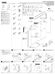
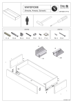
THEBOLD LOOK
"KOHLER.
Installation and Care Instructions
Sliding Shower and Bath Doors
K-702200, K-702202, K-702204, K-702206, K-702208, K-702211, K-702213, K-702215, K-702219, K-702221
>
Sliding Bath Doors
Sliding Shower Doors
USA / Canada: 1-800-4KOHLER
Mexico: 001-800-456-4537
www .kohler.com
WARNING: Risk of serious injury.
Damage prior to installation can result in
glass shattering. Inspect the glass and all
parts for damage before installation.
de
de
NOTICE: Do not touch the edges of the tempered
glass with tools or any other hard objects. Do not set
the unframed tempered glass directly on the floor
or any hard surface.
de
de
A
WARNING: Risk of serious injury.
Improper installation can result in glass
shattering. Follow all installation
instructions.
WARNING: Risk of serious injury. Do not
cut tempered glass. Tempered glass will
shatter if cut.
WARNING: Risk of serious injury.
Shower door and side panels can shatter.
Regularly inspect the glass and all parts for
damage, missing, or loose parts.
WARNING: Risk of serious injury.
Always wear safety glasses while cutting
and drilling.
IMPORTANT: Leave this manual for the end user.
Read these instructions before installing or using
this product.
Required Tools
N
7
>>
1/16"
Number 2 Pencil
| Jd
Tin Snips |
3/16" 5/16"
| dd
5/16" Masonry Bit for Tile
A
100% Silicone Sealant
e
Masking Tape
32 Teeth Per Inch Blade Miter Box
Parts Identification
1205305**
Hanger Bracket Kit
1203635**
Hardware Skin Pack
CAUTION: Risk of injury. Do not attempt to cut
tempered glass.
IMPORTANT! Do not cut the top track the same
length as the bottom track.
Walls must be within 3/8" (10 mm) of plumb.
Cover drain with tape to avoid loss of small parts.
Follow the silicone sealant manufacturer's
instructions for application and curing time.
Measure distance "A." Subtract 1/4" (6 mm) or
the width of a number 2 pencil from "A" and cut
the bottom track.
ZA A ANY
< y
NX /
1/4" (6 mm)
Cut Line "A" Mark
\ 7
7
$5 A
corners.
Position the bottom track on the center of the
ledge. If needed, file the ends to match the
Position the wall jambs over the bottom track.
Plumb both wall jambs. Mark the screw holes.
(2) EN
и” N
7
~~
~~
DES
\ N
Se
> EES
LL
N
Remove the wall jambs. Drill 5/16” holes into the
walls and insert the anchors.
Apply 100% silicone sealant in the groove on the
underside of the bottom track. Secure the bottom
track to the ledge along the marked location.
AM
8
Top Track*
*Call Customer Care Center to order replacement parts.
*Finish/color code must be specified when ordering.
Retain this document for future servicing.
Record model number from box for reference.
Model Number:
1051142-A
/ Serew Model Number Label
/ 1044585 DA
/ Roller
-—— À #8-32 x 3/8"
| | Wall Jamb*
|<) | Outside Panel*
> 1199426-01**
E 1131838** 1199110 Hanger Bracket
M Bumper Gasket
1050048-B
о Barrel Nut
pd De
8-32 x 1/4" 9
и
1077763-А | >
1077762 Sex Bolt A
Anchor № №
A
| ÿ
IN
>. |
> AA Inside Panel
&
(Includes
A 1048208-C (Silver) Hardware)* CD
q 1048208-F (Brass) SOS.
Ne _Screw TSI
> O Ds \
| WW! > Su
J 1031943** “Oo | N
| Screw Cover >> | |
TTT Wall Jambt - H+
e
ta
@
> |
Wall Jamb
Notch
1017813-01** (K-702200, K-702204, K-702206) ° NY
1017813-02** (K-702208)
1017813-03** (K-702202)
1017813-05** (K-702211, K-702221)
1017813-06** (K-702213)
1017813-07** (K-702215) 1031943**
1017813-08** (K-702219) Screw Cover
Inside-Panel Guide
<n) 1048208-B (Silver)
1048208-K (Brass)
48-18 x 3/8" crew
‘ча
| A
| de |
o
- 10070.45 (Silver) 7
| | 10070.46 (Brass) 7
| 10070.30 (Nickel)
10070.72 (Bronze)
= Bottom Track
Wall Jamb
Notch
Center the bottom track on the ledge with the
bottom-track leg to the outside. Tape the bottom
track in place and mark the position.
So
>
|
a | | Bottom- Track
À | Leg
Important! The bottom track and wall jamb must
sit flat against the shower ledge and the wall. If
needed, trim and file the wall jamb. Use a coin to
match and to transfer the corner radius of the
shower to the wall jamb.
©
Screw Cover
#8-18 x 1-1/2"
Reposition both wall jambs. Secure the wall jambs
with screws. Attach a bumper at the top and
bottom locations.
Measure distance “B” above the wall jambs.
Subtract 1/32" (1 mm) or the width of a saw
blade from “B.” Mark and cut the top track.
Top Track
ti
IN
N
/
N DS (
1/32" (1 тт)
Cut Line 1 "B" Mark
| | \ 7
<< Y
00 —
1
1204880-2-B
Reversible
Position the top track over the wall jambs. Either
side of the top track can face out.
For both doors, slide a gasket over the top of the
glass panel and into each mounting hole. Press
the hanger bracket over the gasket and align the
hanger brackets with the mounting holes.
Hanger
Bracket
>
Gasket J
E
\ \\
CL
Lift the inside panel onto the inside track. The
label faces the outside of the shower.
Y
г
On the outside panel, assemble a roller to the
middle hole of each hanger bracket. Place the
rollers on the same side as the outside-panel leg.
|
Uncoated |
Side
/ |
|
|
|
2 | — _——
\
N |
Leg
-J
Assemble both towel bars with a spacer on each
side of the door panel. Use a hex wrench to
tighten the screws. Do not overtighten!
©
| BD ]
| |
| |
| |
l___ne_ "|
1/4"-20 Screw ” e.
D ` Da,
oor |
Рапе! \ Spacers >
>. Towel Bar
a
=
Da
#8-32x 3/8" — la
Roller ?
Screw
> Xx
While pressing downward on the hanger
brackets, use screwdrivers to thread the sex bolt
into the barrel nut. Tighten until the hanger
brackets are secured firmly in place.
Hanger
Bracket
Lift the outside panel onto the outside track. The
label faces the outside of the shower. The
outside-panel leg fits over the bottom-track leg.
Outside the shower, use 100% silicone sealant to
seal along the entire length of the wall jambs and
the bottom track.
Outside-Panel
>
NE
NN
On the inside panel, assemble a roller to the
middle hole of each hanger bracket. Place the
rollers on the same side as the door-frame holes.
Door-Frame Holes
Lay the inside panel flat and partially thread the
screws into the panel.
18-18 x 3/8"
If either panel needs adjustment, remove the door
and position the rollers in new holes to raise or
lower the glass.
MW Lower the glass.
о©°
Raise the glass. 7 a
Install the inside-panel guide onto the partially
threaded screws. The inside-panel guide fits into
the bottom-track slot. Install screw covers over
the side screws.
Screw Cover | ]
\
\,
®
47
№
Inside the shower, use 100% silicone sealant to
seal along the entire length of the wall jambs and
in the corners where the wall jambs meet the
bottom track.
TROUBLESHOOTING
Symptom: Alignment
Recommended Action
1. The top of the door panel is tilted away from the
wall.
A. Remove the door panel from the top track and lower the roller that is closest to the wall. See step 18.
2. The bottom of the door panel is tilted away from
the wall.
A. Remove the door panel from the top track and raise the roller that is closest to the wall. See step 18.
3. The door panel does not touch the bumper.
A. Determine whether door panel top or bottom is closer to the wall, and then adjust the roller closest to the wall.
Symptom: Water Leaks
Recommended Action
1. Water leaks between panels.
A. When showering, make sure the inside panel is against the showerhead wall.
2. Water leaks between the wall jamb and
the door panel.
A. Adjust the door panel to line up with the wall jamb.
3. Water leaks under the bottom track.
A. Check for proper silicone sealant application. See steps 21 and 22. Apply more silicone sealant in the leak location.
4. Water leaks around the wall jamb area.
A. The notched wall jamb fits over the bottom track to cover any miscut or skewed cuts. Seal as directed to ensure
proper watertight seal. See step 22.
Symptom: Operation (open/close)
Recommended Action
1. The outside panel is difficult to move.
A. Ensure a gap exists between the bottom track and the door panel. If no gap exists, lower the rollers to the next hole.
B. Ensure the panel is properly engaged over the bottom track. See step 17.
C. Ensure the rollers are properly installed. See steps 16 and 17.
D. Clean any debris in the top track groove.
2. The inside panel is difficult to move.
A. Ensure a gap exists between the bottom track and the door panel. If no gap exists, lower the rollers to the next hole.
B. Ensure the inside-panel guide is properly secured to the bottom frame screws. See step 19.
C. Ensure the rollers are properly installed. See steps 13 and 15.
D. Clean any debris in the top track groove.
ONE-YEAR LIMITED WARRANTY
KOHLER plumbing products are warranted to be free of defects in material and workmanship for one year from
date of installation.
Kohler Co. will, at its election, repair, replace or make appropriate adjustment where Kohler Co. inspection discloses
any such defects occurring in normal usage within one (1) year after installation. Kohler Co. is not responsible for
removal or installation costs. Use of in-tank toilet cleaners will void the warranty.
To obtain warranty service contact Kohler Co. either through your Dealer, Plumbing Contractor, Home Center or
E-tailer, or by writing Kohler Co., Attn.: Customer Care Center, 444 Highland Drive, Kohler, WI 53044, USA, or by
calling 1-800-4-KOHLER (1-800-456-4537) from within the USA and Canada, and 001-800-456-4537 from within
Mexico, or visit www .kohler.com within the USA, www.ca.kohler.com from within Canada, or www.mx.kohler.com
in Mexico.
IMPLIED WARRANTIES INCLUDING THAT OF MERCHANTABILITY AND FITNESS FOR A PARTICULAR
PURPOSE ARE EXPRESSLY LIMITED IN DURATION TO THE DURATION OF THIS WARRANTY. KOHLER
CO. AND/OR SELLER DISCLAIM ANY LIABILITY FOR SPECIAL, INCIDENTAL OR CONSEQUENTIAL
DAMAGES. Some states/provinces do not allow limitations on how long an implied warranty lasts, or the
exclusion or limitation of special, incidental or consequential damages, so these limitations and exclusions may not
apply to you. This warranty gives you specific legal rights. You may also have other rights which vary from
state/province to state/province.
This is Kohler Co.'s exclusive written warranty.
1204880-2-B
© 2014 Kohler Co.