1
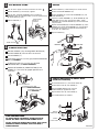
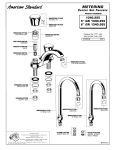
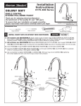
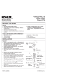
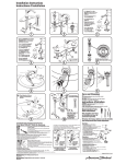
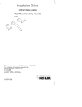
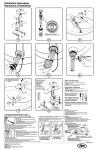
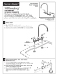
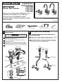
Installation
Instructions
METERING
1340.225
1340.255
1340.265
Center Set Faucets
Thank you for selecting American-Standard...the
benchmark of fine quality for over 100 years.
1340.225
1340.255
To ensure that your installation proceeds
smoothly--please read these instructions carefully
before you begin.
1340.265
Certified to comply with ANSI A112.18.1
M968493
Recommended Tools
Channel Locks
Tubing Cutter
1
Adjustable Wrench
2
INSTALL FAUCET
CAUTION
Turn off hot and cold water supplies before beginning.
Plumbers' Putty or Caulking
2.5mm Hex Wrench
MAKE WATER SUPPLY CONNECTIONS
NOTE: FLEXIBLE SUPPLIES OR BULL-NOSE RISERS MUST BE
PURCHASED SEPARATELY.
Connect water supply to FAUCET (1) with 1/2" IPS FLEXIBLE
SUPPLIES (1) or 3/8" O.D. BULL-NOSE RISERS (2).
Apply a bead of PUTTY along the edge of the
underside of the FAUCET (1).
Insert faucet SHANKS through holes of SINK or
MOUNTING SURFACE.
Install GASKET (2), FRICTION WASHER (3), DEEP
WASHER (4) and LOCK NUT (5). onto SHANKS (6).
Use adjustable wrench to tighten connections. Do not over
tighten. Be careful not to kink copper supply when bending.
Use tubing cutter to cut to proper length.
Tighten LOCK NUTS (5) firmly to secure FAUCET (1).
1
1
COUPLING NUT
SHANK
2
PUTTY
SINK OR
MOUNTING
SURFACE
FERRULE
2
3
4
5
3
5
TEST INSTALLED FITTING
SERVICE
Turn on water supplies and check connections for leaks.
Remove HANDLE (1). Refer to Step 4 for handle removal.
Remove AERATOR (1) with KEY (2) supplied.
Remove ACTUATOR ASSEMBLY (2).
Operate HOT and COLD HANDLES by pressing down on
HANDLES. Both Hot and Cold handles are set for approximately
8 second operating cycles.
Remove WASHER (3). Pull out VALVE ASSEMBLY (4) and
FILTER SCREEN (5).
Inspect that VALVE ASSEMBLY (4), FILTER SCREEN (5) and
VALVE SEAT (6) are clean and free from debris. VALVE
ASSEMBLY (3) and FILTER SCREEN (5) can be cleaned with
soap and water.
PRESS HANDLE
DOWN TO
OPERATE
Replace AERATOR (1).
Replace FILTER SCREEN (5) and VALVE ASSEMBLY (4). Place
WASHER (3) on top of VALVE ASSEMBLY (4). Thread VALVE
ACTUATOR (2) onto faucet. Torque VALVE ACTUATOR (2)
to 12-15 ft. lbs (15-20 Nm).
Replace HANDLE (1).
1
1
2
WATER SUPPLIES
4
REMOVE
REPLACE
2
TO ADJUST CYCLE TIME
Remove HANDLE (1) by removing INDEX BUTTON (2)
and SET SCREW (3) with a 2.5mm hex wrench.
3
Pull off HANDLE (1).
4
To increase cycle time, turn the gray PLASTIC ADJUSTING
NUT (4) clockwise.
To decrease cycle time, turn the gray PLASTIC
ADJUSTING NUT (4) counter-clockwise.
5
Replace SET SCREW (3), INDEX BUTTON (2) and
HANDLE (1). Test faucet for proper operation and
cycle time.
3
2
1
2.5mm HEX WRENCH
TO DECREASE CYCLE TIME
ROTATE COUNTER-CLOCKWISE
TO INCREASE CYCLE TIME
ROTATE CLOCKWISE
6
CONVERT RIGID SPOUT TO SWIVEL SPOUT
(1340.255; 1340.265)
Unthread SPOUT NUT (1) and remove SPOUT (2)
Remove SPOUT CLIP (3) and O-RINGS (4).
Replace RUBBER RING (5) with separate
PLASTIC RING (6) supplied with faucet.
Replace SPOUT CLIP (3) and O-RINGS (4).
Reassemble SPOUT (2) TO BODY.
2
4
1
REMOVE
RUBBER RING
5
3
CARE INSTRUCTIONS:
DO: SIMPLY RINSE THE PRODUCT CLEAN WITH CLEAR
WATER. DRY WITH A SOFT COTTON FLANNEL CLOTH.
DO NOT: CLEAN THE PRODUCT WITH SOAPS, ACID, POLISH,
ABRASIVES, HARSH CLEANERS, OR A CLOTH WITH A
COARSE SURFACE.
INSTALL
PLASTIC RING
4
6
M968493