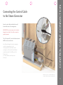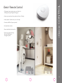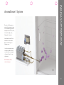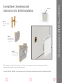
1
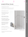
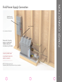
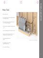
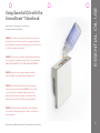
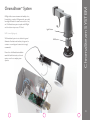
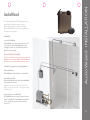
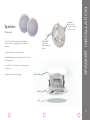
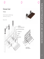
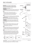
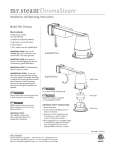
General Guidelines for Installing Mr.Steam Steambath Systems ® The directions detailed in this guideline are designed to familiarize the reader with a general understanding of the installation of a variety of Mr. Steam products. For complete and important detailed Installation, Operation and Maintenance information, it is recommended that reference be made to the specific Mr.Steam® installation manual that accompanies each Mr. Steam product. Any questions, feel free to contact Mr.Steam® at 1-800-76-Steam, [email protected] or visit www.mrsteam.com Generator Location ........................................................ Power Connection ........................................................ Water Feed .................................................................... Steam Oulet ................................................................... Drain Line ....................................................................... AutoFlush ...................................................................... Drip Pan ......................................................................... Express Steam ............................................................... Generator Schematic...................................................... Tandom Generator Installation ...................................... iSteam Control .............................................................. iSteam Installation ........................................................ iTempo Controls ............................................................. iTempo Installation ........................................................ Remote Temperature Sensor .......................................... Remote Temperature Probe ......................................... Control Cable Connection ............................................. iGenie Control ................................................................ AromaSteam System........................................................ AromaSteam Installation.................................................. Essential Oil Use............................................................... ChromaSteam System...................................................... AudioWizard Installation ................................................. Speaker Installation.......................................................... Shower Seat Installation................................................... 2 3 4 5 6 7 8 9 10 11 12 13 14 15 16 17 18 19 20 21 22 23 24 25 26 CONTENTS CONTENTS GENERATOR LOCATION Locating the Mr.Steam Generator ® Select a location as near as practical to the steam room. Typical locations include: closet, vanity cabinet, climate controlled attic or basement. 1. Locate steambath generator within 60 feet of steam room. Note: The standard length of the cable for connecting the control to the steam generator is 30 feet. The steam generator and control must be located accordingly. A 30 foot cable is standard. Contact Mr.Steam to purchase an optional 60 ft. cable (PN 103990-60) for iTempo controls. A 60 foot cable is available for use with iSteam controls (PN 104117-60). 2. DO NOT install steambath generator inside steam room. 3. DO NOT install steambath generator outdoors or wherever environmental conditions may affect the safety and/or performance of the generator. 4. DO NOT install steambath generator or plumbing lines in unheated attic or any locations where water could freeze. 5. DO NOT install steambath generator near flammable or corrosive materials or chemicals such as gasoline, paint thinners, or the like. Installation in areas having high concentrations of chlorine (such as pool equipment room) must be avoided. 6. Install steambath generator on a solid and level surface. Keyhole slots are provided for wall mounting. Insure the steam generator is properly secured and level when mounting with keyhole slots. 7. Install steambath generator in an upright position only. 8. Install a Pressure Reducing Valve to limit supply to 15-20 PSIG. 9. Install anti-water hammer device as necessary. 10. Provide a minimum of (12) inches at both ends and top of the steam generator or as required for servicing. For Illustrative purposes only. Consult with qualified designer, architect or contractor for steamroom construction details. 2 Main Electrical Disconnect Panel 240v Powerline L1, L2, Ground to be field wired Please refer to the wiring diagram in the Mr.Steam Installation Manual for complete wiring information. POWER CONNECTION Field Power Supply Connection _________________________________ TO AVOID EQUIPMENT DAMAGE DO NOT CONNECT POWER SUPPLY DIRECTLY TO ELEMENTS!!! ________________________________ NOTE: For illustrative purposes only. Consult with qualified licensed electrician for electrical installation. 3 1. Connect cold water line. 2. Provide a shut off valve in the water supply line upstream of the steambath generator. Water Feed Line (3/8” NPT) WATER FEED Water Feed 3. Do not overheat inlet solenoid valve with solder connections. Overheating will damage parts. 4. Flush inlet water line thoroughly before making connection to unit. 5. Strainer recommended upstream of feed water connection. 6. For best performance water pressure should be 15 to 20 PSIG. Reduce pressure as required if necessary. 7. Provide anti-water hammer device as required. For Illustrative purposes only. Consult with qualified designer, architect or contractor for steamroom construction details. 8. As required by local codes, install an approved backflow preventer. 9. Do not use PEX or PVC tubing. 4 Steam Outlet (1⁄2” NPT) 1. Do not install any valve in steam line. Flow of steam must be unobstructed. 2. Use 1⁄2” brass pipe or copper tubing from unit to steam head as permitted by codes. Steam Outlet Pipe STEAM OUTLET Steam Outlet Pipe 3. Insulate steam line using pipe insulation rated 250˚ F or higher. 4. Pitch steam line 1⁄4” per foot towards steam head or steam generator to avoid valleys and trapping of condensation. NOTE: Running the steam line down and then up will create a steam trap blocking the flow of steam. NOTE: A 1.5” hole in the steamroom is required to mount the steamhead. For Illustrative purposes only. Consult with qualified designer, architect or contractor for steamroom construction details. 5 DRAIN LINE Manual Drain Line Drain (1⁄2” NPT) NOTE: A drain valve is provided to facilitate servicing. Provide a drain line connection from steambath generator drain valve according to national and local codes. Check local plumbing code for receptor, trap and vent requirements. Unit drains by gravity. Manual Drain Valve (Shown in open position) Pitch as required for Gravity Drain For Illustrative purposes only. Consult with qualified designer, architect or contractor for steamroom construction details. 6 AutoFlush Optional AutoFlush Steam Generator Operation The optional AutoFlush System feature automatically drains the Mr.Steam® system following each use. A time delay allows the water to cool down (about two hours) before it drains by gravity for a safe and gentle operation. NOTE: If the Express Steam option has been installed, the AutoFlush will drain for ten minutes then refill with fresh water to begin the pre-heat cycle. Drain Valve Plumb to drain line (shown in open position) DO NOT REMOVE DRAIN VALVE Installation Instructions Copper or Brass Nipple 1. Plumbing to be performed by a qualified plumber and shall be in accordance with applicable national and local codes. Unit drains by gravity. A drain line that is lower than the AutoFlush assembly must be available. The AutoFlush System 1 valve outlet is ⁄2” NPT. Check plumbing code for receptor, trap and vent requirements. 1 1/2” x3 1/2” or longer (not supplied) Arrow indicates correct direction of flow AutoFlush Shown Fully Assembled 1 2. Use copper or brass nipple ⁄2” NPT x 3 ⁄2” or longer (not supplied) to connect AutoFlush valve to the Drain Valve. An arrow on the bottom of the AutoFlush indicates the direction of flow. ! PROVIDE DRAIN PLUMBING ACCORDING TO LOCAL CODES. PLUMB AS REQUIRED FOR AUTOFLUSH SYSTEM. CA U T I O N 7 DRIP PAN Drip Pan PN 103867 Drip Pan 3/4” Outlet For Illustrative purposes only. Consult with qualified designer, architect or contractor for steamroom construction details. 8 Express Steam Express Steam (only available factory installed) Suitable for all MS Models. Express Steam is equipped with a low power heating element and thermostat to keep the water in the tank warm enough to produce steam quicker. All Express Steam components and wiring are installed at the factory. No additional wiring or plumbing is required by installers. Thermostat Express Steam Heating Element 9 GENERATOR SCHEMATIC Generator Schematic (MS SUPER 2E shown) Power Block Fuses Liquid Level Control Board Contactor Transformer Liquid Level Probe Water Feed Solenoid Power Supply Knock-Out Water Inlet Plug and Play Connection Access Cover Safety Valve Steam Outlet Express Steam Heater (optional) AutoFlush Valve (optional) Heating Element Stainless Steel Tank Drain Line 10 TANDOM INSTALLATION Tandem Steam Generator Installation (MS Super 4E, 5E & 6E)* Standard Tandem Cable for Connecting (2) Units PN 103904 • Optional Tandem Cable for Connections up to (5) Units PN 103917 Secondary Unit Primary Unit (Unit control connected to Primary Unit) *Refer to the Mr.Steam Installation manual for additional installation information. For Illustrative purposes only. Consult with qualified designer, architect or contractor for steamroom construction details. 11 iSteam CONTROL iSteam Control 12 iSteam INSTALLATION Installing the iSteam Control Install the iSteam Control according to the installation and operation instructions supplied with the Control. Failure to do so may result in an inoperative control and a hazardous condition. 1. Plug the 30’ control cable into the iSteam control pigtail. The iSteam pigtail is the longer cable with the ID tag. 2. If the optional AudioWizard is used, remove the red Cap from the AudioWizard pigtail and plug it into the AudioWizard cable. 3. Carefully guide cables within the wall housing, then place iSteam control into final position (Diagram 3). Diagram 1 Diagram 2 Diagram 3 CAUTION Do not force or twist cable ends together. Forcing or twisting cable ends may damage the connectors. 13 Locate control where it will sense general room temperature and NOT direct steam emission from the steam head. iTempo CONTROLS iTempo® and iTempo Plus® Controls Refer to the Mr.Steam iTempo Installation Manual for complete control installation information. 14 1. Firmly connect the connector to the control. Turn on power to the steam generator and test the control to verify correct connections. Test per instructions. Proceed with installation and verification of proper control function. IMPORTANT: Turn power to the steam generator OFF before installing the control. Failure to turn the power OFF will result in an inoperable control. 2. Remove and discard peel-off paper to expose adhesive liner. 3. Run a bead of silicone on reverse side edge of iTempo control (silicone provided). iTempo INSTALLATION Installing the iTempo® or iTempo Plus® Control 4. Insure the mounting surface is clean and dry as required for good adhesion. Apply silicone into the hole in the wall as required to create a moisture seal. Hold the control with the LED display in the 12 o’clock position and press the control against the wall until the adhesive sticks and holds firmly as shown above. 15 MSTS Remote Temperature Sensor Locate the Remote Temperature Sensor (MSTS) where it will sense general room temperature and NOT direct steam emission from the steam head. Refer to the Mr.Steam Installation manual for additional control installation information. REMOTE TEMPERATURE SENSOR Locating Controls Outside the Steam Room by Using Remote Temperature Sensor For Illustrative purposes only. Consult with qualified designer, architect or contractor for steamroom construction details. 16 The Remote Temperature Probe is required when a steam control is installed outside the steam room. 1. The probe must be installed: a. On a vertical surface. b. 4-5’ above the floor. Locate the probe in a location representative of the desired steambathing temperatures. Do not locate the probe above or near the steam head or direct steam emissions. The probe has an integral 20 ft. cable. Ensure that the probe and iSteam control are located accordingly. Diagram 1 2. Drill a 1/4” hole in the wall. Do not oversize or undersize the hole. Clean area thoroughly. 3. Route the end of the temperature probe cable with the temperature probe through the wall into the steam room as shown in Diagram 1. Diagram 2 IMPORTANT NOTE: Do not strain, staple, pinch or otherwise damage the probe cable. 4. With a minimal length of the cable exposed apply silicone (provided) to the hole in the wall as required to create a moisture seal as shown in Diagram 2. 5. Push the iMSTS cable and probe into the hole as required to leave between 1/4”- 1/2” of the probe. Exposed as shown in Diagram 3. Diagram 3 REMOTE TEMPERTURE PROBE Installing a Remote Temperature Probe 6. Insure a minimum of 1/4” of the probe is exposed to the air. Failure to do so may result in an inoperative control and a hazardous condition. The exposed area of the probe must be free of silicone or any materials that prevent direct exposure to the steam room air. Failure to do so may interfere with the ability to sense temperature and may result in excessive steam room temperatures. 17 CONTROL CABLE CONNECTION Connecting the Control Cable to the Steam Generator Route the control cable (provided with the control) from the wall cutout to the steam generator. IMPORTANT: Do not strain, staple, pinch or otherwise damage the control cable. Route cable as required to permit replacement. The 30’ (and optional 60’) control cable features identical Mini-Din connectors at both ends. Note: The standard length of the cable for connecting the control to the steam generator is 30 feet. The steam generator and control must be located accordingly. A 30’ cable is standard. Contact Mr.Steam to purchase an optional 60’ cable (PN 103990-60) for iTempo controls. A 60’ cable is available for use with iSteam controls (PN 104117-60). For Illustrative purposes only. Consult with qualified designer, architect or contractor for steamroom construction details. 18 ® • Fully automatic water resistant remote control with color indicating status ring and magnetic docking port. • Activate your steam shower from anywhere in the home - Wirelessly. • Initiates preheat of steam shower up to 100 feet away. • Penetrates walls! Radio Frequency activated. • Easy Plug & Play connection. • Comes standard with interface module. • Can be easily connected with any Mr.Steam® Bath Generator (No upgrade required). iGenie CONTROL iGenie Remote Control 19 Electronic oil delivery system evenly infuses aroma into steam for an aromatherapy experience. Complete with in-shower control, oil container caddy, hoses, fittings and oil atomizer. AromaSteam Essential Oils are available in one-liter bottles. Not for use with acrylic or fiberglass rooms. AromaSteam SYSTEM AromaSteam™ System Locate Aroma steam system in an easily accessible location so as to monitor the consumption of essential oils and for easy replacement. NOTE: Cables should not contact steam pipe. 20 Oil Well Step 1 Attach Locating Nipple to steam line. Step 2 Provide a 1 ½” hole in finished wall to mount the steamhead. Step 3 Remove Locating Nipple and attach steam head. AromaSteam INSTALLATION AromaSteam™ Steamhead and Optional Acrylic Shield Installation NOTE: Steamhead to be installed 6-12” above the floor. A 1.5” diameter hole in the steamroom is required to mount the steamhead. Refer to the AromaSteam Steamhead Manual for additional installation information. The Acrylic Shield (PN 103938SQ ) is to be used when acrylic or other non-heat resistant materials are used for the steamroom enclosure. 21 Enjoy essential oils by placing a drop or two into your steamhead as shown in the illustration. CAUTION: Use essential oils with caution. Essential oils are for external use only. Keep out of reach of children. Essential oils are highly concentrated and are potent substances and should not be applied directly to the skin as they can be irritants. Use essential oils with caution. CAUTION: Place the drops into the Mr.Steam AromaSteam steamhead well prior to turning on the steambath. Do not place drops in a hot steam head as SERIOUS INJURY CAN RESULT IF YOU DO NOT FOLLOW THIS WARNING. ESSENTIAL OIL USE Using Essential Oils with the AromaSteam™ Steamhead CAUTION: Start with one drop to gauge strength and suitability. Limit to a maximum of a few drops during a steambathing session. CAUTION: Some people may find that the aroma makes them dizzy and the user should exit the steam bath IMMEDIATELY. If skin irritation occurs, stop using the oils immediately. Remove any excess oil by washing in mild soap and water. If ingested, rinse mouth with water. Administer water or milk to dilute. Contact a physician immediately. CAUTION: Essential oils and/or aromatherapy can cause inflammation, burns, headache, nausea and allergic reactions. Consult a physician before using aromatherapy. Close containers, tightly, when storing oils. Keep away from sources of ignition. 22 LED light suffuses steam environment with multiple colors, from airy blue to sensual red. Ceiling mounted, vapor-sealed, low-voltage LED module for steam shower enclosure of any size. The ChromaSteam system is complete with LED light and color election microprocessor. ETL Listed. Light Fixture NOTE: for mood lighting only. The ChromaSteam System is not a substitute for general illumination. Consultation with architect, designer and or contractor on room design and construction is strongly recommended. Please refer to the ChromaSteam installation manual for detailed instruction, as this unit requires a 120v line to complete system operation. LED Cluster ChromaSteam SYSTEM ChromaSteam™ System 23 Mr. Steam’s AudioWizard offers fully integrated audio control inside the steam room and or shower. With an integrated Blue Tooth Audio Streaming System, the AudioWizard can pair up to eight devices and four in-shower speakers. INSTALLATION 1) Locate the AudioWizard The AudioWizard control cable is 30ft and the power cord is 6ft, ensure the control and AudioWizard are located accordingly. Locate in a dry location where the wireless signal will not be interrupted. CAUTION: ELECTRIC SHOCK HAZARD! To reduce the risk of fire or electric shock, do not expose this apparatus to rain or moisture. DO NOT install AudioWizard in the steam room or any location where it may become wet. 2) Test Bluetooth® signal before mounting AudioWizard. 3) Mount AudioWizard The AudioWizard should be installed on a vertical surface. 4) Install AW Control Cable Route the AudioWizard control cable from the AudioWizard to the desired control location. If using an iSteam control see the iSteam Control IOM (PUR 100477) for complete details on locating and installing the iSteam control. AudioWizard INSTALLATION AudioWizard 5) Connect the Control to AudioWizard® The AudioWizard must be connected to either the iSteam Control® or the AW Control. AudioWizard is supplied with a 30 ft. cable that has 6-pin mini-din male connectors on each end. 24 Speakers Rotate out for speaker installation in wall or ceiling MS-Speakers • Two 51⁄2” diameter flush-mount two-way speakers for steam or shower use, polypropylene cones or ABS frames with grills. Silicone RTV Apply silicone bead around entire speaker • Suitable for almost any source of audio input. • Rated 60W peak power 8 ohms impedance with 1” tweeter for full range sound. • Use only CL2 or CL3 UL listed wires to connect speakers to audio source. • Available in round and square designs. Wall or Ceiling SPEAKER INSTALLATION Brackets Speaker Grill 25 MS-Seat Teak wood seat drops for use and folds for storage. Dimensions are: 19 5⁄8” w x 12 5⁄8” d x 11⁄4” Max 250 lbs. rated on 16"nter ce ical typ Wall Brackets Note correct orientation as shown #12, 3 inch long flat head screw Wall Bracket Cover Hinge Pin Caps Seat Assembly 195/8" 125/8" SHOWER SEAT INSTALLATION Shower Seat Completed Assembly Shown in seating position 26 facebook.com/mrsteamtherapy twitter.com/steamtherapy pinterest.com/steamtherapy youtube.com/steamtherapy Sussman-Automatic Corporation® 43-20 34th Street, Long Island City, NY 11101 Tel: 718 937 4500 Fax: 718 472 3256 9410 S. La Cienega Blvd. Inglewood CA 90301 Tel: 310 216 6565 Fax: 310 216 2944 houzz.com/mr-steam 2013 © Sussman-Automatic Corporation MR. STEAM and des., A LIFETIME OF PLEASURE, AROMAFLO, AUTOFLUSH, CLEAN STEAM...EVERY TIME, CLUB THERAPY, DIGITAL 1, eTEMPO, eTEMPO/PLUS, FROM BATHROOM TO SPA, MAKING WELLNESS a WAY of LIFE, MUSIC THERAPY, STEAM ON DEMAND, STEAM@HOME, STEAM GENIE, STEAMTHERAPY, and SUSSMAN are registered trademarks of Sussman-Automatic Corporation. AROMASTEAM, BUTLER PACKAGE, CHROMASTEAM, EXPRESS STEAM, HOME WIZARD, STEAM STOP, THE INTELLIGENT STEAMBATH and VALET PACKAGE are trademarks of Sussman-Automatic Corporation. PUR 100431 11/13 www.mrsteam.com CONNECT WITH MR. STEAM Feel Good Inc.