1
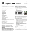
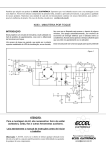
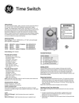
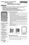
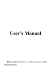
Digital Time Switch
SPECIFICATIONS
Input Voltage: 120 VAC, 208/240 VAC, or 277 VAC in all units based
upon dipswitch configuration.
Switch Rating: DPDT Models
Normally Open Contacts
40A Resistive, 120-277Vac.
30A General Purpose, 120-277Vac.
20A Resistive, 30Vdc
1 HP, 120Vac ; 2HP, 240Vac ;
20A Ballast, 120-277Vac.
15A Tungsten, 120Vac
5.4A Tungsten, 208-277Vac.
800VA, Pilot Duty, 120Vac.
720VA, Pilot Duty, 240-277Vac.
TV-5, 120Vac
Normally Closed Contacts
30A Resistive, 120-277Vac
15A General Purpose, 120-277Vac
15A Resistive, 30Vdc
20A Ballast, 120-277Vac
1/4HP, 120Vac; 1/2HP, 208-240Vac.
290VA, Pilot, 120Vac.
360VA, Pilot, 208-240Vac.
NOTE: If loads are connected to both NC and NO contacts, both contacts are
derated to 67% of the above values.
ENVIRONMENTAL RATINGS
Ambient Temperature: –40F to 130F
Humidity: 0-95% RH, Non-condensing
WIRING CONNECTIONS
Screw clamp terminals for up to 2, 8 AWG wires per position. For supply
connections, use 8AWG or larger wires suitable for at least 105° C. Use copper
conductors only.
Lights
Power LED (Orange) – Light illuminates when power is applied to
the timer
Status LED (Green) – Light illuminates when power is applied to load.
INSTALLATION
CAUTION: Before wiring or service, power to this time switch and the
equipment it controls must be turned off. Turning off the timer switch only
will not prevent a shock hazard. Replace cover plate within housing before
supplying power to time switch. Installation should be performed by a
licensed electrician only. Before installing this product read all instructions
carefully. Remove protective cover panel within time switch housing by
removing screws located below timer face.
Dipswitch Configuration
WARNING: Failure to properly configure the dipswitch will result in
damage to the unit and void the warranty! Before installing and wiring the GE
Time Switch, proper configuration must be selected. This is accomplished as
follows:
120VAC
ON
OFF
208~240VAC
ON
OFF
277VAC (Default)
ON
OFF
ALL ON
1 & 4 OFF
2 & 3 ON
ALL OFF
NOTE: For outdoor locations, rain tight or wet location conduit hubs that
comply with requirements of UL 514B (standard for fittings for conduit and
outlet boxes) must be used.
1. To mount the box, remove the timer mechanism. Push the latch at the
top of the timer mechanism. The mechanism will release and pull out of
box.
2. Select knockouts to be used. Remove the inner 1/2” knockout by
inserting a screwdriver in the slot and carefully punch knockout loose.
Remove slug. If the 3/4” knockout is required, remove the outer ring
with pliers after removing the 1/2” knockout. Smooth edges with file if
necessary.
3. Place enclosure in desired mounting location and mark the three
mounting holes.
4. Drill holes for #8 screws using 1/8” drill bit, start screws in holes.
5. Place enclosure over screws and tighten screws.
6. Connect conduit hubs to conduit before connecting the hubs to the
enclosure. After inserting hubs into enclosure, carefully tighten hub lock
nut. Do not over-tighten.
7. Install in accordance with all applicable National and Local code
requirements. See Figure 1 and wiring diagrams.
8. To place the timer mechanism back in the metal box timer first hold top
of the timer mechanism. Slide the plastic case into the metal box latches
in the center of the metal box. Push the top of the timer mechanism until
the metal latch snaps into place.
GROUNDING: This enclosure has a grounding block on the bottom/
inside of the timer box. Screw in all ground wires to the ground block.
A pool application does not require bonding.
This enclosure does not provide grounding between conduits. When using
non-metallic conduit or cable, connect the ground wires of all cables together
with a wire nut. When metallic conduit is used, use grounding type bushings
and a jumper wire between each conduit.
15136
Figure 1
MIN.
MINIMUM MAX.
COPPER LOAD INSULWIRE SIZE (AMP) ATION
TEMP(°C)
(AWG)
14
12
10
8
15
20
30
40
60
60
60
105
75°C INSULATION MAX. MOTOR
LOAD (HP)
SINGLE PHASE
120 V.
240 V.
1/2
1
2
-
2
2 1/2
3
5
PRESSURE PLATE
3 PHASE
208 V.
240 V.
N/A
TERMINAL SCREW
MAKE SURE WIRE
INSULATION CLEARS
PRESSURE PLATE
N/A
Typical Wiring Diagrams—SPDT
Typical Wiring Diagrams—DPDT
Timer and Load, Same Voltage
Wired as Single Throw
120V Timer, 200/240/277V Load Double Break
Wired as Single Throw
T
T
TIMERN NC
TO POWER SUPPLY
TIMERN
H
TO 120V LINE
OC OM
TO LOAD
CN
TO 200/240/277V LINE
LOAD
N
Timer and Load, Different Voltage
Wired as Single Throw
O COM NC2 NO2 COM2
120V Timer, 120V Load and 24V Load
Wired as Single Throw
T
T
TIMERN
CN OC OM
TIMERN
H
TO 120V LINE
N
N
TO LOAD
H
TO POWER SUPPLY 2
LOAD
TO POWER SUPPLY 1
120V Two Speed Fan
Wired as Double Throw
T
CN O COM NC2 NO2 COM2
TO 24V LINE
LOAD
200/240/277V Timer, 200/240/277V Load, Double Break
Wired as Single Throw
T
H
N
TIMERN
CN OC OM
HIGH
LOW
COM
L1
Field Wiring
Timer Internab Wiring
L2
TO 120V LINE
TIMERN
CN
O COM NC2 NO2 COM2
LOAD
Operating Instructions
(Reset)
H(Hours Setting)
M(Minutes Setting)
Day
(Days Setting)
LCD
(Function Figures)
Clock
(Current Time Setting)
Timer
(9 Programs Setting)
Override
(Manual ON/OFF Switched)
Basic Settings
Initial Set Up:
1. Push the Reset button “R” before programming to clear out any settings.
Once the “Reset” button is pressed the screen will begin to flash. A
paperclip may be needed for this step.
(If the “Reset” button is shown down, use a paper clip to maneuver it until it
pops back up. The screen will flash if the button is in its proper position)
2. Press the “Clock” button and the screen will stop flashing and be ready for
programming.
Setting the Current Time:
1.
2.
3.
4.
5.
Press and Hold the “Clock” button during the entire setting.
Press the “H+” button to set the hours.
Press the “M+” button to set the minutes.
Press the “Day” button to set the day of the week.
Release the “Clock” button.
Programming ON/OFF Settings:
1. Press the “Timer” button once and the TIMER 1 ON - - : - - appears.
2. Press the “H+” and “M+” button to set the hours and minutes to the
desired time.
3. Press the “Day” button to select the day(s) the setting will be active. Refer
to the Multiple Weekday Group below to see the available settings.
4. Press the “Timer” button to store the setting and proceed to the next
setting TIMER 1 OFF - - : - -.
5. Repeat steps 1-4 to program the remaining ON/OFF times setting options
(9 Total ON/OFF settings). Once completed press the “Clock” button to
return to the main display.
Multiple Weekday Groups:
Apart from individual week days, pressing the “Day” button also selects
multiple day combinations such as:
‧ Monday thru Friday
‧ Tuesday & Thursday & Saturday
‧ Saturday & Sunday
‧ Monday thru Wednesday
‧ Monday thru Saturday
‧ Thursday thru Saturday
‧ Monday & Wednesday & Friday
‧ Monday thru Sunday
After setting a single day or a multi-day-combination the programmed timer
settings will be carried out on each of the week-days at the same time.
15136
Programming Countdown Operation:
1. Press the “Timer” button replacing to scroll through the 9 ON/OFF settings
to get to the ON C setting.
2. Press the “Override” button to select whether the timer will turn ON or OFF
during teh countdown period.
3. Press the “H+” and “M+” buttons to set the hours and minutes of the
countdown.
4. Press the “Clock” button to store the setting and return to the current time
display. See the diagram below for more information.
Activate the Countdown Feature:
1. Press the “Clock” and “Override” buttons at the same time to start the
countdown function.
2. Press the “Override” button to pause and continue the countdown
function.
3. Press the “Clock” button to go view the current time display.
Summer Time Feature (DST):
Press the “H+” and “M+” buttons for 3 seconds to advance the current time
1 hour, SUMMER should appear on the display. Repeating this process will
decrease the time by 1 hour and SUMMER will disappear.
Power Back Up Feature:
In the event of a power failure, the timer will retain its settings for an
estimated 3 months assuming the power back up is fully charged.
Button Lock:
This function allows the user to lock the buttons so that they are not
accidentally pressed.
1. Press and HOLD the “Clock” button for more than 5 seconds. An
“
“ icon will appear on the display. The buttons are now locked. To
unlock the buttons repeat this step.
Manual Override:
The timer comes with the ability to control the ON and OFF function while
the timer is deactivated. Press and Hold the “Override” button to switch
between timer mode and manual mode. Timer mode will be indicated by an
A next to the ON or OFF. When the timer is in manual mode (not controlled by
timer) the A will not appear on the display. Any time the “A” is displayed the
timer is in control and will always follow the programmed settings (even if it is
temporarily deactivated by moving from ON to OFF or OFF to ON).
Random, ON/OFF Setting:
This feature allows the timer to switch ON and OFF at random times. It is
particularly useful in helping to prevent burglary as the timer is not switching
ON and OFF at regular times. The programmed settings will be executed in a
random delay varying within 30 minutes. This function will only operate if one
or more programmed switching commands are set.
1. Press both “Day” and “H+” buttons at the same time. The display will show
the “TIMER” symbol blinking. The random feature is now activated.
2. To turn the random feature off repeat step 1.
Note:
“
“ Flashing: the timer is in the manual mode with key lock.
“
“ Not flashing: the timer is in the timer mode with key lock.
Lockout a Programmed Setting (Skip a Setting):
1. Press the “Timer” button repeatedly to scroll to the setting that needs to
be skipped.
2. Press the “Override” button to lockout the time setting. The display will
display “H I : d E” and lock the hours and minutes setting.
3. Press the “Override” button again to recall the setting time. This Function
(Will not work for Lockout Countdown feature)
15136