Transcript
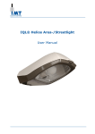
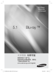
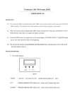
X-RC7098
REMOTE CONTROLLER WIRING CHART
Warning:
Before installing Remote Controller,
make sure the Main Power Supply is turned off.
AC : 110-130V/60HZ
LIGHT : 165W ( MAX )
FAN : 85W ( MAX )
Step 1: To Set Frequency before making wire connection.
* There is a Frequency Setter respectively in Transmitter
& Receiver (as figure 1). When produced, all of 4 keys
on the frequency setters are in "ON" position. Basically, Antenna
customers do not need to adjust the frequency and
the remote control.
* If you buy one more remote controlled fan or the
frequency is interrupted, the fan may function abnormally.
In this situation, you need to change the fan frequency.
There are 16 modes of setting frequency for you to
select the best channel to operate the fan (see figure 2).
Following are the 16 modes for your channel selection.
Please use a pin to switch the keys carefully.
ON DI P
K ey
" OFF" position
3.) When 3 keys are in "OFF" position.
4.) When 4 keys are in "ON" or "OFF" position.
1
2
3
4
1
2
3
4
1
2
3
4
1
2
3
4
1
2
3
4
1
2
3
4
1
2
3
4
1
2
3
4
1
2
3
4
1
2
3
4
1
2
Step 2: To make wire connection.
Wire from Outlet Box to Red Wire from
* White
Receiver with "AC IN N" sticker.
* Receiver with "AC IN L" sticker.
Black Wire from Outlet Box to Red Wire from
* Blue Wire from Receiver to Blue Wire from Motor.
* White Wire from Receiver to White Wire from Motor.
Black Wire from Receiver to Black Wire from Motor.
Wire from Receiver to Brown Wire from Motor.
* Brown
Wire from Outlet Box to Green Ground Wire
* Ground
from Motor bracket & Down Rod.
the battery (not included) to transmitter.
* Install
Turn on the electric power. Press button to operate the fan.
Neutral Wire From
Outlet Box
(White Wire)
1
3
4
( Fig 1.)
2 3 4
1
*** Please note to change the frequency-setters in the transmitter
& receiver at the same time & in the same key position.***
1.) When 1 key is in "OFF" position.
2.) When 2 keys are in "OFF" position.
" ON" position
2
3
4
1
2
1
3
4
2
3
4
1
2
3
4
1
2
3
4
( Fig 2.)
Hot Wire From
Outlet Box
(Black Wire)
Red Wire with
Red Wire with
"AC IN N" sticker
"AC IN L" sticker
Ground Wire
( Green Wire)
Receiver
Fan