1
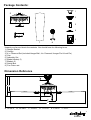
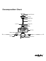
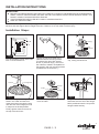
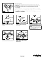
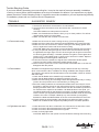
LIMITED LIFETIME WARRANTY
Model No.: FN52265
aireRyder ORIGINAL CEILING FAN LIMITED LIFETIME WARRANTY
The limited lifetime warranty covers this ceiling fan, for residential use by the original purchaser, against defects in
material or workmanship as follows:
If your aireRyder Ceiling Fan motor fails at any time during the lifetime of the original purchaser due to defects in
material or workmanship, we will provide a replacement part free of charge.
If your Fan motor fails at any time within one year after the original date of sale to the original purchaser due to defects
in material or workmanship, we will provide labor to repair the defect, with the exception of take down/reinstallation,
free of charge. The original purchaser will be responsible for all labor costs after this one year period.
If no replacement parts are provided for any part of your Fan motor that fails at any time during your lifetime due to
defects in material or workmanship, we will refund the original purchase price of your Fan.
If your Fan blades, pull chain switch, reverse switch, or any accessory, except glass globes and light bulbs, fails at any
time within one year after the original date of purchase due to a defect in material and workmanship, we will repair or, if
we choose, replace the defective blades, switch, or accessory free of charge, with the exception of take
down/reinstallation services.
If the original purchaser ceases to own the Fan, this warranty and any implied warranty, including but not limited to any
implied warranty of merchantability or fitness for a particular purpose, become void. This warranty and any implied
warranty, including but not limited to any implied warranty of merchantability or fitness for a particular purpose, do not
cover glass globes, light bulbs, or finish on any metal portions of the Fan.
This warranty is in lieu of express warranties. The duration of any implied warranty of merchantability or fitness for a
particular purpose, with respect to any aireRyder Ceiling Fan motor, blades, switch, or accessories, is expressly
limited to the period of the express warranty set forth above for such motor, blades, switch, or accessories.
This warranty excludes defects, malfunctions, or failures of any aireRyder Ceiling Fan that are caused by repairs by
persons not authorized by us, use of parts or accessories not authorized by us, mishandling, improper installation,
modifications or damage to the Fan while in your possession, or unreasonable use, including failure to provide
necessary maintenance.
In no event shall aireRyder Fan be liable for consequential or incidental damages.
Some states do not allow the exclusion or limitation of consequential or incidental damages, in which case the above
limitation or exclusion may not apply.
This warranty gives you specific legal rights and you may also have other rights which vary from state to state.
TM
Package Contents:
1
9
2
3
4
8
5
6
7
Unpack your fan and check the contents. You should have the following items.
1.) Hanger Bracket
2.) Canopy
3.) 4 in. Downrod Set (Included Hanger Ball, 4 in. Downrod, Hanger Pin & Lock Pin)
4.) Cap
5.) Assembly Set
6.) Blade Holder(x 5)
7.) Blade(x 5)
8.) Switch Box
9.) Fan Fixture set
Dimension Reference
E
C
B A
D
F
A. 13-3/4 in.
B. 14-3/8 in.
C. 2-3/8 in.
D. 11-1/4 in.
E. 5-1/8 in.
F. 52 in.
TM
060220
Decomposition Chart:
Hanger Bracket
Canopy
Hanger Ball
Downrod
Lock Pin
Hanger Pin
Cap
Collar
Housing
Blade Holder
Blade
Switch Box
TM
060220
Safety Instructions
READ ALL SAFETY INFORMATION AND INSTALLATION INSTRUCTIONS BEFORE YOU BEGIN
INSTALLING THE FAN. SAVE INSTRUCTIONS.
All set screws of the fan must be checked and retightened where necessary before installation.
To reduce the risk of personal injury, do not bend the blade brackets when installing the brackets,
balancing the blades or cleaning fan. Do not insert foreign objects in between rotating fan blades.
Before changing the fan direction, turn off the fan and wait for the fan blades to stop completely.
If a stationary appliance is not provided with a supply cord and a plug, or with other means for
disconnection from the supply mains having a contact separation of at least 3 mm in all poles, that
means for disconnection must be incorporated in the fixed wiring in accordance with the wiring rules.
NOTE: The safeguards provided by these safety instructions and by the separate installation
instructions are not meant to cover all possible conditions and situations that may occur. It must be
understood that common sense, caution and care are factors which can not be built into this product.
These factors must be supplied by the person(s) installing, caring for and operating the fan.
WARNING
TO AVOID RISK OF ELECTRIC SHOCK, BE SURE TO SHUT OFF POWER AT THE MAIN
FUSE OR CIRCUIT BREAKER BOX BEFORE INSTALLING OR SERVICING THIS
FIXTURE.
TO REDUCE THE RISK OF INJURY, INSTALL THE FAN SO THAT THE BLADES ARE
AT LEAST 7 FEET (2.1 METERS) ABOVE THE FLOOR AND AT LEAST 18 INCHES
(0.5 METERS) FROM THE TIP OF THE BLADES TO THE WALL.
TO REDUCE THE RIST OF FIRE, ELECTRIC SHOCK, OR PERSONAL INJURY, MOUNT
TO OUTLET BOX MARKED "ACCEPTABLE FOR FAN SUPPORT" AND USE MOUNTING
SCREWS PROVIDED WITH THE OUTLET BOX.
THE INSTALLATION HAS TO BE IN ACCORDANCE WITH THE NATIONAL ELECTRICAL
CODE AND LOCAL CODES, ANSI/NFPA 70-1999 AND LOCAL CODES. IF YOU ARE
UNFAMILAR WITH THE METHODS OF INSTALLING ELECTRICAL WIRING, SEEK THE
SERVICES OF A QUALIFIED LICENSED ELECTRICIAN.
TM
060220
INSTALLATION INSTRUCTIONS
IMPORTANT:
BEFORE YOU BEGIN INSTALLING THE FAN, CAREFULLY READ ALL INFORMATION ON THE SEPARATE
SHEET "SAFETY INSTRUCTIONS" AS WELL AS THE FOLLOWING "INSTALLATION INSTRUCTIONS". IF IN
DOUBT, CONSULT A QUALIFIED ELECTRICIAN.
THIS FAN MUST BE INSTALLED WITH A WALL CONTROL/SWITCH.
SAVE ALL INSTRUCTIONS.
NOTE: The fan weight is 22.89 lb (10.3 kg). Be sure the outlet box you are using is securely attached to the building
structure and and support the full weight of the fan. Failure to do so can result in serious injury.
Installation Steps :
Canopy
Cap
Downrod
Fig.2.
Fig.1.
Turn off the electric power at the main
fuse or circuit breaker box.
Fig.3.
Tighten the hanger bracket to the
outlet box with 2 mounting screws.
(To reduce the risk of fire, electric
shock, or personal injury, mount it to
the outlet box marked "Acceptable for
fan support" and use mounting screws
provided with the outlet box.)
Insert the motor wires through the
cap, canopy and downrod.
Slot
Lock Pin
Hanger Pin
Downrod
Collar
Fig.4.
Insert the hanger pin through the
holes in the collar and downrod.
Insert the lock pin through the hole
near the end of the hanger pin until
it snaps into its locked position.
Finally, tighten downrod screws on
the top of the fan motor.
Cap
Housing
Chip
Fig.6.
Fig.5.
Attach the cap onto the housing to
cover the collar.
Hang the fan on the hanger bracket,
and make sure the slot of the hanger
ball is positioned onto the chip of the
hanger bracket exactly.
TM
PAGE: 1 / 3
060220
Make wires connection:
1). The motor white wire to the white wire from the outlet box with a wire nut.
2). The motor black wire and blue wire to the black wire from the outlet box with
a wire nut.
3). The ground wire from the outlet box to the ground wire from the motor
with a wire nut.
*** After making the wire connections, the wires should be spread apart with the
grounded conductor and the equipment-grounding conductor on one side and
the underground conductor on the other side of the outlet box.
*** After the splices have been made, they should be turned upward and pushed
carefully up into the outlet box.
Green ( Ground )
Blue
Fig.7.
Blade Screw
Canopy Screw
Washer
Blade
Plastic
insert
Fig.8.
Fig.9.
Attach the canopy to the hanger
bracket and secure it with canopy
screws.
Blade Holder
Tighten the blades to the blade
holders by using the blade screws
and washers.
Fig.10.
Secure the blade holders to the motor
with the motor screws and washers.
NOTE:
Before installing blade holders
to the motor, please remove the
plastic inserts.(See fig.8)
Set Screw
Pull Chain
Switch Cover
Fig.11.
Switch Box
Connect the two terminals respectively
from the motor and the switch box.
Fig.12.
Secure the switch box with the set
screws. Use pull chain to control
the fan speed.
TM
PAGE: 2 / 3
060220
Trouble Shooting Guide
If you have difficulty operating your new ceiling fan, it may be the result of incorrect assembly, installation
or wiring. In some cases, these installation errors may be mistaken for defects. If you experience any faults,
please check this Trouble Shooting Guide. If a problem cannot be remedied or you are experiencing difficulty
in installation, please call our Customer Service Department.
TROUBLE
SUGGESTED REMEDY
1. If fan does not start:
1. Check main and branch circuit fuses or circuit breakers.
2. Check line wire connections to fan and switch wire connections in switch
housing.
CAUTION: Make sure main power is turned off.
3. Make sure forward/reverse switch is firmly in up or down position. Fan will not
operate when switch is in the middle.
4. Make sure that the wall controler is turned "ON".
2. If fan sounds noisy:
1. Make sure all screws in motor housing are snug. (not over tightened)
2. Make sure the screws which attach the fan bladeholder to the motor are tight.
3. Make sure wire nut connectors in switch housing are not rattling against each
other or against the interior wall of the switch housing.
CAUTION: Make sure main power is turned off before entering switch housing.
4. If using an optional ceiling fan light kit, check to be sure the screws securing
the glassware are finger tight. Check to be sure light bulb is tight in socket and
not touching glass shade(s). If vibration persists from glass, remove glass and
install a 1/4 in. wide rubber band on glass neck to act as an insulator. Replace
glass and tighten screws against rubber band.
5. Some fan motors are sensitive to signals from Solid State variable speed
controls. DO NOT USE a Solid State variable speed control.
6. Allow "break-in" period of 24 hours. Most noises associated with a new fan will
disappear after this period.
3. If fan wobbles:
All blades are weighed and grouped by weight. Natural woods vary in density
which could cause the fan to wobble even though all blades are weight-matched.
The following procedures should eliminate most of the wobble. Check for wobble
after each step.
1. Check that all blades are screwed firmly into blade holders.
2. Check that all blade holders are tightened securely to motor.
3. Make sure that canopy and mounting bracket are tightened securely to ceiling
junction box and junction box is mounted firmly to ceiling joist.
4. Most fan wobble problems are caused when blade levels are unequal. Check
this level by selecting a point on the ceiling above the tip of one of the blades.
Keeping measure within 1/8 in. rotate the fan until the next blade is positioned
for measurement. repeat for each blade. If all blade levels are not equal, you
can adjust blade levels by the following procedure. To adjust a blade tip down,
insert a washer (not supplied) between the blade and blade holder at the screw
closest to the motor. To adjust a blade tip up, insert washer (not supplied)
between the blade and blade holder at the two screws farthest from the motor.
5. If blade wobble is still noticeable, interchanging two adjacent (side by side)
blades can redistribute the weight and possibly result in smoother operation.
4. If light does not work:
1. Check blue wire from fan to make sure it is connected to hot wire from house.
2. Check for loose or disconnected wires in fan switch housing.
3. Check for loose or disconnected wires in light kit.
4. Check for faulty light bulbs.
CAUTION: Make sure main power is turned off before entering switch housing.
TM
PAGE: 3 / 3
060220