1
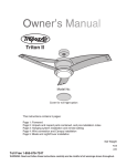
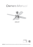
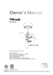
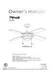
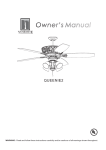
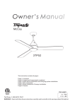
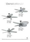
Owner’s Manual
ZEPHYR
UL
R
WARNING : Read and follow these instructions carefully and be cautious of all warnings shown throughout.
READ AND SAVE THESE INSTRUCTIONS
Warning: To avoid the risks of fire, electrical shock or injury,
please observe the following:
1.
To ensure the correct and complete installation, be sure to read the instructions and review the diagrams
carefully and thoroughly before beginning installation.
2.
If possible, mount the ceiling fan on a ceiling joist. The joist must be able to support the motion and weight
of the moving fan. If the fan will be mounted on a ceiling outlet box, a 4" x 2-1/8" deep METAL octagon box is
required; one UL listed as "suitable for fan support ". The box and its supporting members must not be able
to twist or work loose. DO NOT USE PLASTIC BOXES. Installation on a concrete ceiling should be
performed by qualified personnel.
3.
Blades should be attached after motor housing is hung and in place. Fan motor housing should be kept in
the carton until ready to be installed to protect its finish. If you are installing more than one ceiling fan, make
sure that you do not mix fan blade sets.
4.
Make sure that your installation site will not allow rotating fan blades to come in contact with any object.
Blades should be at least 7 feet from the floor when fan is in operation.
5.
To avoid any possible accidents such as electric shock, be sure ceiling fan is not connected to power source
before wiring. All electrical connections must be made in accordance with local codes, ordinances and/or
the National Electric Code. If you are unfamiliar with the methods of installing electrical wiring and
products, secure the services of a qualified and licensed electrician as well as someone who can check the
strength of the supportive ceiling members and make the proper installations and connections.
6.
See wire connection instruction for your guide. Electrical diagrams are for reference only. Read the
instructions carefully and connect wires correctly and completely.
7.
After making electrical connections, spliced conductors should be turned upward and pushed carefully up
into the outlet box. The wires should be spread apart from the grounded conductor. Ground conductor
should be placed opposite to the outlet box from the "HOT" wires.
8.
After fan is completely installed, double check everything to make sure that all connections are secure to
prevent fan from falling and/or causing damage or injury.
9.
The fan can be used immediately after installation. The bearings are adequately charged with grease so
that, under normal condition, further lubrication should not be necessary.
Important Notes:
1.
2.
3.
The fan must be turned off and at a complete stop before reversing fan direction.
Light kits that are not packed with the fan must be UL or CUL listed and should be installed per light kit's
installation instructions.
This fan is suitable for indoor locations only.
P1
1. Unpack and inspect fan carefully to be certain all contents are
included.
Hardware bag
Up Glass Shade
Remote Control
Transmitter
Mounting
Bracket
Suitable for use with solid - state
speed control
Canopy
Bulbs
2 pcs
Spring Washer
3 pcs
Lock Washer
3 pcs
Wood Screw
3 pcs
Tooth Washer
3 pcs
Blade Balance Kit
Up-Light
E-12, 15W x 4pcs.
Downrod
Assembly
Mounting Screw
Fan Assembly
Hardware bag
Screw
2 pcs
Wire Nut
7 pcs
Wire Nut
Motor Screw
1 pc
4 pcs
9 pc
Screw For Spring
3 pcs
Leaf Spring
3 pcs
Blade
Yoke Cover
Down Glass Shade
Outlet Box
Mounting
Bracket
OFF OFF OFF
4.
2.
3.
Turn off power at the breaker
box to avoid possible
electrical shock.
Use a metal outlet box suitable for
fan support.
Be sure that the box can support
a minimum weight of 40 pounds.
Secure the outlet box directly to the
building structure using wood
screws (provided).
Install the mounting bracket
to outlet box in the ceiling
using the washers and the
mounting screws provided
in the hardware bag.
Do not use existing
mounting bracket
in the outlet box.
5. Yoke & Downrod Assembly
Downrod Assembly
Canopy
Wire Connectors
from Yoke Cover
Jam Screw
Yoke Cover
Cross Pin
Yoke
Take cotter pin and cross pin off from downrod assembly.
1.Insert downrod assembly through canopy & yoke cover
as shown above.
2.Feed motor lead wires through downrod assembly.
3.Insert the downrod assembly into yoke.
4.Insert the cross pin through Yoke and downrod and
secure with Cotter Pin.
5.Tighten both set screws to further secure downrod.
6.Tighten hex nuts existing on set screws toward yoke
to prevent set screws from loosening.
7.Connect 9-pin connectors, pull down the yoke cover
& fasten jam screw on top of yoke cover.
Wire Connectors
from Fan
Set Screw
with Hex Nut(2)
Cotter Pin
P2
6. Up Glass Shade Assembly
Glass Screws x 3
Spring Clip x 3
Up Glass Shade
Canopy
Yoke Cover
Light Bulb x 4
Grill
Place the up glass shade onto grill & secure the
glass shade with three glass screws / spring
clips on grill.
Gently install E-12 (4pcs.) Light bulbs on lampholders.
7. Hanging the fan
Mounting
Bracket
Ridge
Mounting
Bracket
Ball Notch
Fan Assembly
(2)
Rotate fan so that the ball notch engages the
ridge in the mounting bracket.
(1)
Carefully lift fan assembly onto
mounting bracket.
7-2.
IMPORTANT: THE WOOD SCREW AND ITS SUPPORT MUST
BE ABLE TO FULLY SUPPORT THE WEIGHT OF AT LEAST 100 LBS.
To ensure safely install the secondary support as follows:
(1). Using the wood screw and flat washer provided.
Pass through close loop of safety cable to wood screw.
(2). Secure the wood screw to ceiling joist and make sure
the safety cable has been tightened securely.
Safety cable
P3
II - Remote Control
1.Prepare the parts of the remote control.
Receiver
Code Switches
2
3
4
4
1 2 3
1
Transmitter
Code Switches
2. Setting the code on the transmitter.
2-1. Remove the battery cover of the remote control.
2-2. Slide code switches to your choice for an ON and OFF position. Use a small screwdriver to slide each
of the switches.
2-3. Install a 9V DC battery ( included).
2-4. Install battery covers on transmitter.
3. Setting the code on the receiver:
3-1. Slide the code switches to the receiver. Be sure that the code is similar to the code set at the
transmitter.
4. For remote control wiring connection to the fan:
4-1. Follow the diagram below and be sure that exposed wires are secured inside wire nuts or the
terminal block.
Note: Wires from the house may vary in color and may not include ground wire (green).
4-2. When the wiring is completed, gently push wires into the junction box with wire nuts pointing upward.
From House
White
White
(AC-N)
From Fan
From Remote
c
Bla
White
k
White
Blac
k
Bl
ue
O
ra
ng
e
Black
(AC-L)
( Motor - N )
Black
( Motor - L )
Blue
( for light kit )
Orange
( for up light kit )
Green
Green
( from downrod )
( for ground wire )
Green
( from mounting bracket )
Secure with twist - lock wire nuts (Included).
III. Install the canopy
Key Holes
1.
Push up the Canopy until the two screws on mounting bracket
are engaged with Key Holes in canopy.
Canopy
2.
Rotate the canopy slightly until the two screw heads are in the
small end of the Key Holes.
3.
Tighten both screws.
Screw
P4
IV - Blades installation
1.Remove the plate at the light kit housing that covers the fan-shaped hole.
2.Insert the fan blades into the fan-shaped hole.
3.Secure the blade into the motor assembly by using the washer and the motor screws which are provided.
4.Repeat the steps 2-3 until 4 blades are assembled.
5.Re-attach the plate in place after blade installation is completed.
Motor
Assembly
Blade
Fan-shaped Hole
Blade
Plate
Washer
Blade Screw
Plate
V - Light Kit Installation
[ With Light ]
[ No Light ]
Light Kit Pan
Light Kit
Pan
Groove
Glass Shade
Bulb
Bottom plate
Lamp Holder
(1).
1.Install the bulbs (not included)
to the lamp holders (sockets) properly.
(2).
Attach the glass shade by
screwing it onto the light kit
pan clockwise.
(1).
Attach the bottom plate by
screwing it clockwise onto
the light kit pan.
TURN ON THE POWER. INSTALLATION IS SUCCESSFUL
AND THE FAN IS READY FOR OPERATION.
P5