1
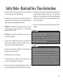
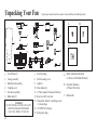
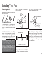
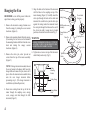
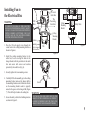
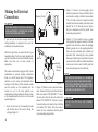
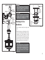
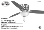
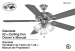
640 656
Garrison
52 in Ceiling Fan
Owner’s Manual
Garrison
Ventilador de Techo de 1,32 m
Manual del Propietario
52” Garrison
Thank you for purchasing our ceiling fan. This product has been
manufactured with the highest standards of safety and quality.
Ceiling Fan by Hampton Bay
Date Purchased
Table of Contents
Store Purchased
Safety Rules . . . . . . . . . . . . . . . . . . . . 1
UL Model No.
640-656
Unpacking Your Fan . . . . . . . . . . . . . . 2
Installing Your Fan . . . . . . . . . . . . . . . 3
Serial No.
Installing the Light Kit. . . . . . . . . . . . .10
Operating Your Transmitter . . . . . . . . . 12
Vendor No.
11289
Care of Your Fan . . . . . . . . . . . . . . . . 14
Troubleshooting . . . . . . . . . . . . . . . . . 14
UPC
792145352778
Specifications . . . . . . . . . . . . . . . . . . 15
Warranty Information . . . . . . . . . . . . 16
Safety Rules - Read and Save These Instructions
1. To reduce the risk of electric shock, insure electricity has been turned off 10. After making electrical connections, spliced conductors should be turned
upward and pushed carefully up into outlet box. The wires should be
at the circuit breaker or fuse box before beginning.
spread apart with the grounded conductor and the equipment-grounding
conductor on one side of the outlet box and ungrounded conductor on the
2. All wiring must be in accordance with the National Electrical Code
other side of the outlet box.
“ANSI/NFPA 70-1999” and local electrical codes. Electrical installation
should be performed by a qualified licensed electrician.
11. All set screws must be checked and retightened where necessary before
installation.
3. WARNING: To reduce the risk of electrical shock or fire, do not use this
fan with any solid-state fan speed control device. It will permanently
damage the electronic circuitry.
WARNING
4. CAUTION: To reduce the risk of personal injury, use only the screws
provided with the outlet box.
5. The outlet box and support structure must be securely mounted and
capable of reliably supporting a minimum of 50 pounds, Use only UL
Listed outlet boxes marked “FOR FAN SUPPORT.”
6. The fan must be mounted with a minimum of 7 feet clearance from the
trailing edge of the blades to the floor.
7. Avoid placing objects in path of the blades.
8. To avoid personal injury or damage to the fan and other items, be
cautious when working around or cleaning the fan.
TO REDUCE THE RISK OF PERSONALL INJURY, DO NOT BEND THE
BLADE ARMS (ALSO REFERRED TO AS FLANGES), WHEN
INSTALLING THE BRACKETS, BALANCING THE BLADES OR
CLEANING THE FAN. DO NOT INSERT FOREIGN OBJECTS IN –
BETWEEN ROTATING FAN BLADES.
WARNING
TO REDUCE THE RISK OF FIRE, ELECTRIC SHOCK, OR PERSONAL
INJURY, MOUNT TO OUTLET BOX MARKED "ACCEPTABLE FOR FAN
SUPPORT OF 22.7 KG (50 LBS.) OR LESS" AND USE MOUNTING
SCREWS PROVIDED WITH THE OUTLET BOX. MOST OUTLET BOXES
COMMONLY USED FOR THE SUPPORT OF LIGHT FIXTURES ARE NOT
ACCEPTABLE FOR FAN SUPPORT AND MAY NEED TO BE REPLACED.
DUE TO THE COMPLEXITY OF THE INSTALLATION OF THIS FAN, A
QUALIFIED LICENSED ELECTRICIAN IS STRONGLY RECOMMENDED.
9. Do not use water or detergents when cleaning the fan or fan blades. A dry
dust cloth or lightly dampened cloth will be suitable for most cleaning.
1
Unpacking Your Fan
2
Unpack your fan and check the contents. You should have the following items:
6
3
1
A
10
B
13
4
7
11
8
5
9
C
14
12
15
1.
2.
3.
4.
5.
6.
Set of blades (5)
Canopy assembly
Ball/downrod assembly
Coupling cover
Fan motor assembly
Blade arms (5)
WARNING
DO NOT INSTALL OR USE FAN IF ANY
PART IS DAMAGED OR MISSING.
CALL TOLL FREE 1-877-898-1881.
2
Switch housing
Switch housing cover
Light kit
Glass shades (4)
13 Watt compact fluorescent bulbs (4)
Receiver with 6 wire nuts
Transmitter+holder+2 mounting screws
+ 2 plastic plugs
14 12V MN21/A23 battery
15. Extra plastic plug
7.
8.
9.
10.
11.
12.
13.
A. Blade Attachment Hardware
(16 Screws with Rubber Washers)
B. Electrical Hardware
(3 Plastic Wire Nuts)
C. Balance Kit
Installing Your Fan
Tools Required
Figures 1~3 are examples of different ways to
mount the outlet box.
heavy duty fan brace as shown in Figure 2
(available at any Home Depot store).
Phillips screwdriver, straight slot screwdriver, step
ladder and wire cutters.
Provide Strong Support
Mounting Options
Outlet Box
Mounting bracket
opening must be
toward the top
If there isn't an existing UL listed mounting box,
then read the following instructions. Disconnect
the power by removing fuses or turning off circuit
breakers.
Secure the outlet box directly to the building
structure. Use appropriate fasteners and building
materials. The outlet box and its support must be
able to fully support the moving weight of the fan
(at least 50 lbs). Do not use plastic outlet boxes.
Figure 1
Figure 3
Note: You may need a longer downrod to
maintain proper blade clearance when installing
on a steep, sloped ceiling. The maximum angle
allowable is 18°. If the canopy touches downrod,
remove the decorative canopy bottom cover and
turn the canopy 180° before attaching the canopy
to the mounting plate.
Heavy Duty Fan Brace
WARNING
TO REDUCE THE RISK OF FIRE, ELECTRIC
SHOCK OR PERSONAL INJURY, MOUNT FAN
ONLY TO AN OULET BOX MARKED ACCEPTABLE FOR FAN SUPPORT AND USE THE
MOUNTING SCREWS PROVIDED WITH THE
OULET BOX. OUTLET BOX COMMONLY USED
FOR THE SUPPORT OF LIGHTING FIXTURE
MAY NOT BE ACCEPTABLE FOR FAN SUPPORT
AND MAY NEED TO BE REPLACED. CONSULT A
QUALIFIED ELECTRICIAN IF IN DOUBT.
Recessed
Outlet Box
Heavy Duty Outlet Box for Fan
Figure 2
To hang your fan where there is an existing fixture
but no ceiling joist, you may need an installation
3
Hanging the Fan
5. Align the holes at the bottom of the downrod
with the holes in the coupling on top of the
motor housing (Figure 5). Carefully insert the
REMEMBER to turn off the power. Follow the
clevis pin through the holes in the collar and
steps below to hang your fan properly.
downrod. Be careful not to jam the clevis pin
against the wiring inside the downrod. Insert
1. Remove the decorative canopy bottom cover
the cotter pin through the hole near the end of
from the canopy by turning the cover counter
the clevis pin until it snaps into its locked
clockwise. (Figure 4)
position, as noted in the circle inset of Fig. 5.
2. Remove the mounting bracket from the canopy
by loosening the two screws on the bottom of
the mounting bracket a half turn from the screw
head and turning the canopy counter
clockwise. (Figure 4)
3. Remove the clevis pin, cotter pin and set
screws from the top of the motor assembly.
(Figure 5)
NOTE: If a longer downrod is needed, take out
the screw located in the hanger ball, lower the
hanger ball and remove the pin, remove all 3
pieces from the downrod and assemble them
onto the new longer downrod before
proceeding step 4. (The longer downrod is
available at any Home Depot store)
4. Route wires exiting from the top of the fan
motor through the coupling cover, canopy
cover, canopy and then through the ball/
downrod. (Figure 5)
4
WARNING
Motor Wires
Ceiling Canopy
Ball/Downrod
Assembly
Canopy Bottom
Cover
Cotter Pin
FAILURE TO PROPERLY INSTALL COTTER PIN
AS NOTED IN STEP 5 COULD RESULT IN FAN
LOOSENING AND POSSIBLY FALLING.
6. Tighten two set screws at top of the fan motor
collar firmly and evenly. (Fig. 5)
Pin in Locked
Positioon
Coupling Cover
Clevis Pin
Motor Collar
Tighten Screw
Firmly
Figure 5
Ceiling
Mounting
Bracket
Ceiling Canopy
Canopy Bottom
Cover
Figure 4
Installing Fan to
the Electrical Box
WARNING
TO REDUCE THE RISK OF FIRE, ELECTRIC
SHOCK OR OTHER PERSONAL INJURY. MOUNT
FAN ONLY TO AN OUTLET BOX OR SUPPORTING
SYSTEM MARKED ACCEPTABLE FOR FAN
SUPPORT AND USE THE MOUNTING SCREWS
PROVIDED WITH THE OUTLET BOX.
1. Pass the 120-volt supply wires through the
center hole in the ceiling mounting bracket as
shown in Figure 6.
UL Listed
Outlet Box
Posts in the
Outlet Box
120V
Wires
Washers
Mounting
Screws (Supplied
Ceiling
Mounting
Bracket
Safety Cable
Ceiling
Mounting
Bracket
Figure 8
Tab
with Electrical Box)
Figure 6
2. Install the ceiling mounting bracket to the
outlet box; be sure to align the holes in the
hanger bracket with the post holes in the outlet
box and secure with screws and washers
provided by the outlet box (Fig. 6).
3. Security tighten the two mounting screws.
4. Carefully lift the fan assembly up to the ceiling
mounting bracket and seat the hanger ball in
the mounting bracket socket. Make sure the tab
on the mounting bracket socket is properly
seated in the groove in the hanger ball (Figure
7). This will help to balance the ceiling fan.
5. Secure the safety cable to the building structure
as shown in Figure 8.
Tab
Groove
Figure 7
WARNING
THE TAB IN THE RING MUST REST IN THE
GROOVE OF THE HANGER BALL AS FIGURE 7.
FAILURE TO PROPERLY SEAT THE TAB IN THE
GROOVE COULD CAUSE DAMAGE TO WIRING.
5
Making the Electrical
Connections
3. (Figure 11) Receiver to house supply wires
electrical connections: Connect the black (hot)
wire from the ceiling to the black wire marked
"AC in L" from he receiver. Connect the white
(neutral) wire from the ceiling to the white wire
marked "AC in N" from the receiver. Secure
the wire connections with the plastic wire
connecting nuts provided.
Frequency Switch
WARNING
TO AVOID POSSIBLE ELECTRICAL SHOCK, BE
SURE ELECTRICITY IS TURNED OFF AT THE
MAIN FUSE BOX BEFORE WIRING.
If you feel you do not have enough electrical
wiring knowledge or experience, have your fan
installed by a licensed electrician.
Follow the steps below to connect the fan to your
household wiring. Use the wire nuts supplied with
your fan. Secure the wire nuts with electrical tape.
Make sure there are no loose strands or
connections.
This remote control unit is equipped with 16 code
combinations to prevent possible interference
from or to other remote units. The frequency
switches on your receiver and transmitter have
been preset at the factory. Please recheck to make
sure the switches on the transmitter and the
receiver are set to the same position, any
combination of settings willoperate the fan as long
as the transmitterand receiver are set to the same
position (Figure 9).
1. Insert the receiver into the mounting bracket
with the flat side of the receiver facing the
ceiling as Figure 10.
6
Figure 9
Receiver
Ceiling
Mounting
Bracket
4. (Figure 11) If your outlet box has a ground
wire (green or bare copper) connect it to the fan
ground wires; otherwise connect the hanging
bracket ground wire to the mounting bracket.
Secure the wire connection with a plastic nut
provided. After connecting the wires spread
them apart so that the green and white wires are
on one side of the outlet box and black and blue
wires are on the other side. Carefully tuck the
wire connections up into the outlet box.
NOTE
Figure 10
2. (Figure 11) Motor to eceiver electrical connections: Connect the black wire from the fan to
black wire marked "TO MOTOR L". Connect
the white wire from the fan to the white wire
marked "TO MOTOR N" from the receiver.
Connect the blue wire from the fan to the blue
wire marked "For Light" from the receiver.
Secure the wire connections with the plastic
wire connecting nuts provided.
FAN MUST BE INSTALLED AT A MAXIMUM
DISTANCE OF 20 FEET FROM THE TRANSMITTING UNIT FOR PROPER SIGNAL TRANSMISSION BETWEEN THE TRANSMITTING UNIT
AND THE FAN'S RECEIVING UNIT.
CAUTION
DO NOT USE WITH WALL LIGHT DIMMER
SWITCH.
WARNING
BLACK
BLACK
WHITE
SUPPLY CIRCUIT
Ground
Conductor
Outlet Box
GREEN
WHITE
WHITE
BLUE
BLACK
BLACK
BLUE
WHITE
Green
Ground
Lead
Ground to
Downrod
CHECK TO SEE THAT ALL CONNECTIONS ARE
TIGHT, INCLUDING GROUND, AND THAT NO
BARE WIRE IS VISIBLE AT THE WIRE NUTS.
EXCEPT FOR THE GROUND WIRE.
WARNING
ELECTRICAL DIAGRAMS ARE FOR REFERENCE ONLY. OPTIONAL USE OF ANY LIGHT
KIT SHELL BE UL LISTED AND MARKED
SUITABLE FOR USE WITH THIS FAN.
Finishing the Fan
Installation
1. Tuck connections neatly into ceiling outlet
box.
Outlet Box
Ceiling
Mounting
Bracket
Screws
Canopy
Canopy
Bottom
Cover
Figure 12
2. Slide the canopy up to ceiling and over the 2
screws on the hanger bracket. Rotate canopy
clockwise. Next, while holding the canopy
with one hand, slide the canopy cover over the
screws and rotate clockwise until tight. Note:
adjust the canopy screws as necessary until the
canopy and canopy cover are snug. (Fig. 12)
WARNING
Figure 11
MAKE SURE THE TAB ON THE HANGER
BRACKET PROPERLY SITS IN THE GROOVE
IN THE HANGER BALL BEFORE ATTACHING THE CANOPY TO THE BRACKET BY
TURNING THE HOUSING UNTIL IT DROPS
INTO PLACE.
7
Attaching the Fan Blades
CAUTION
Motor
MOTOR IS SHIPPED WITH MOTOR SUPPORT
PLATE PREVENT MOVEMENT DURING TRANSPORTATION. REMOVE THE SCREWS FROM
THE MOTOR SUPPORT PLATE, DISCARD THE
MOTOR SUPPORT PLATE. (FIG. 13)
Tab
Slot
Motor Support Plate
1. Attach blades to blade arm using the screws
with rubber washers provided (Fig. 14). Start a
screw into the blade arm, do not tighten.
Repeat for the 2 remaining screws and
washers.
Screws
Figure 13
2. Tighten each screw securely starting with the
center screw. Make sure the blade is straight.
Repeat steps for the remaining blades.
3. Fasten the blade assemblies to the motor
housing by lining up the slots of the blade arms
with the tabs on the motor housing, then
tighten the two screws and washers already
installed in the blade arms (Figure 15).
Screws with
Rubber Washers
Figure 15
WARNING
Blade Arm
Blade
Blade Arm
Medallion
Figure 14
8
Blade Arm
TO REDUCE THE RISK OF PERSONAL INJURY,
DO NOT BEND THE BLADE ARMS WHILE
INSTALLING, BALANCING THE BLADES, OR
CLEANING THE FAN. DO NO INSERT FOREIGN
OBJECTS BETWEEN ROTATING FAN BLADES.
Attaching the Switch
Housing
Blade Balancing
The following procedure should correct most fan
wobble. Check after each step.
Touching Ceiling
1. Remove 1 of 3 screws from the mounting ring
and loosen the other 2 screws. (Do not remove)
1. Check that all blade and blade bracket screws
are secure.
2. Most fan wobble problems are caused when
blade levels are unequal. Check this level by
selecting a point on the ceiling above the tip of
one of the blades. Measure from a point on the
center of each blade to the point on the ceiling.
Measure this distance as shown in Figure 16.
Rotate the fan until the next blade is positioned
for measurement. Repeat for each blade.
Measurements deviation should be within 1/8˝.
Run the fan for 10 Minutes.
2. While holding the switch housing under your
fan, snap together the wire connection plugs.
Figure 16
3. Place the key holes on the mounting plate over
the 2 screws previously loosened from the
mounting ring, turn mounting plate until it
locks in place at the narrow section of the key
holes. Secure by tightening the 2 screws
previously loosened and the one previously
removed. (Fig. 17)
3. Use the enclsed Blade Balancing Kit if the
blade wobble is still noticeable.
Wire Connection
Plugs
Mounting Ring
Switch Housing
Screws
Figure 17
9
Installing the
Light Kit.
CAUTION
BEFORE STARTING INSTALLATION, DISCONNECT THE POWER BY TURNING OFF THE
CIRCUIT BREAKER OR REMOVING THE FUSE
AT FUSE BOX. TURNING POWER OFF USING
THE FAN SWITCH IS NOT SUFFICIENT TO
PREVENT ELECTRIC SHOCK.
1. Remove the plug from the switch housing
cover.(Fig. 18) Attach the light kit to the switch
housing cover by feeding the light kit wires
(black and white) through the hole of switch
housing cover and then screw it onto the switch
housing cover by nut & lock washer. Be sure it
is tight enough to prevent light kit from vibrating loose. (Fig. 18)
2. While holding the light kit assembly under
your fan, Make the polarized plug connections:
(Figure 19)
- White to white
- Blue to black
3. Carefully push all wires back into the switch
housing, then install the light kit assembly onto
the mounting plate with 3 screws provided. Be
sure to tighten all screws. (Fig. 19)
10
4. Remove the lock ring from the socket by turning
the lock ring clockwise Until it unlocks. Insert
the glass into the glass holder and turn the lock
ring counter-clockwise to tighten the glass.
Repeat for the remaining glass. (Fig. 19)
5. Install 4 x 13 Watt compact fluorescent bulbs
(included). NOTE: CFL bulbs are NOT
dimmable.
6. Restore power and your light kit is ready for
operation.
Screws
Light Kit
Assembly
Wire Connection
Plugs
NOTE
LIGHT BULBS HAVE NO WARRANTY; CAN BE
PURCHASED AT ANY HOME DEPOT STORE.
Nut
Lock Washer
Plug
Glass Shade
Switch Housing
Cover
Light Kit
Lock Ring
Bulbs
Figure 18
Figure 19
Fan without Light Kit
(Optional)
Your fan is designed with light kit, in case you
intend to install the fan without light kit. Attach
the plastic plug to the switch housing cover. Then
installing the switch housing cover to the switch
housing with the screws provided. (Figure 20)
Switch
Housing
Screws
Switch Housing
Cover
Plug
Figure 20
11
Operating Your Transmitter
Installing the Battery:
Restore power to the ceiling fan and test for
proper operation.
Install 12V MN21/A23 battery (included), to
prevent damage to transmitter, remove the battery
if not used for long periods (Figure 21).
1. "HI, MED, LOW" buttons:
These three buttons are used to set the fan
speed as follows:
LOW=Low speed,
MED= Medium speed
HI=High speed
2. "OFF" button:
This button turns the fan off.
" button turns the light ON or OFF.
3. The "
(NOTE: The light is NOT dimmable.)
Figure 21
12
Figure 22
NOTE
DO NOT OPERATE REVERSING SWITCH
WHILE FAN BLADES ARE IN MOTION. FAN
MUST BE TURNED OFF AND BLADES STOPPED
BEFORE REVERSING BLADE DIRECTION.
Speed settings for warm or cool weather depend
on factors such as the room size, ceiling height,
number of fans, and so on.
The Reverse switch is located on the switch
housing. Slide the switch to the Left for warm
weather operation. Slide the switch to the Right for
cool weather operation.
Figure 23
Warm weather - (Counter-Clockwise direction)
A downward air flow creates a cooling effect.(Fig.
23) This allows you to set your air conditioner on
a higher setting without affecting your comfort.
Cool weather - (Clockwise direction) An upward
airflow moves warm air off the ceiling area. (Fig.
24) This allows you to set your heating unit on a
lower setting without affecting your comfort.
Figure 24
13
Care of Your Fan Troubleshooting
Here are some suggestions to help you maintain
your fan.
1. Because of the fan's natural movement, some
connections may become loose. Check the
support connections, brackets, and blade
attachments twice a year. Make sure they are
secure. (It is not necessary to remove fan from
ceiling.)
PROBLEM
SOLUTION
Fan will not start
1. Check main and branch circuit fuses or breakers.
2. Check line wire connections to the fan and switch wire connections in
the switch housing.
3. Check to make sure the dip switches from the transmitter and receiver
are set to the same frequency.
Fan sounds noysy
1. Make sure all motor housing screws are snug.
2. Make sure the screws that attach the fan blade bracket to the motor hub
is tight.
3. Make sure wire nut connections are not rattling against each other or
the interior wall of the switch housing.
4. Allow a 24-hour "breaking-in" period. Most noises associated with a
new fan disappear during this time.
5. If using an optional light kit, make sure the screws securing the
glassware are tight. Check that the light bulb is also secure.
6. Make sure the upper canopy is a short distance from the ceiling. It
should not touch the ceiling.
7. Make sure your ceiling box is secure and rubber isolator pads are used
between mounting bracket and outlet box.
2. Clean your fan periodically to help maintain its
new appearance over the years. Do not use
water when cleaning. Use only a soft brush or
lint-free cloth to avoid scratching the finish.
The plating is sealed with a lacquer to
minimize discoloration or tarnishing. Do not
use water when cleaning. This could damage
the motor, or the wood, or possibly cause an
electrical shock.
3. You can apply a light coat of furniture polish to
the wood blades for additional protection and
enhanced beauty. Cover small scratches with a
light application of shoe polish.
4. There is no need to oil your fan. The motor has
permanently lubricated sealed ball bearings.
14
Remote control
1. Do not connect the fan with a wall mounted variable speed control(s).
2. Make sure the dip switches are set correctly.
WARNING
MAKE SURE THE POWER IS OFF AT THE ELECTRICAL PANEL BOX
BEFORE YOU ATTEMPY ANY REPAIRS. REFER TO THE SECTION,
“MAKING ELECTRICAL CONNECTIONS”.
Specifications
FAN SIZE SPEED
VOLTS AMPS
LOW
52”
MED.
HIGH
120
WATTS
RPM
CFM
0.35
15
70
2101
0.55
40
120
4244
0.62
73
160
5929
N.W.
G.W.
C.F.
16.8 kgs
(37 Ibs)
19 kgs
(41.8 Ibs)
3.04’
These are approximate measures. They do not include Amps and Wattage used by the light kit .
15
Lifetime Limited Warranty
(lifetime warranty on motor)
The Hampton Bay warrants the fan motor to be free from defects in workmanship and material present at time
of shipment from the factory for a period of lifetime after the date of purchase by the original purchaser.
Hampton Bay also warrants that all other fan parts, excluding any glass or acrylic blades, to be free from
defects in workmanship and material at the time of shipment from the factory for a period of one year after the
date of purchase by the original purchaser. We agree to correct such defects without charge or at our option
replace with a comparable or superior model if the product is returned to Hampton Bay. To obtain warranty
service, you must present a copy of the receipt as proof of purchase. All costs of removing and reinstalling the
product are your responsibility. Damage to any part such as by accident or misuse or improper installation or
by affixing any accessories, is not covered by this warranty. Because of varying climatic conditions this
warranty does not cover any changes in brass finish, including rusting, pitting, corroding, tarnishing or peeling.
Brass finishes of this type give their longest useful life when protected from varying weather conditions. A
certain amount of “wobble” is normal and should not be considered a defect. Servicing performed by
unauthorized persons shall render the warranty invalid. There is no other express warranty. Hampton Bay
hereby disclaims any and all warranties, including but not limited to. Those of merchantability and fitness for
a particular purpose to the extent permitted by law. The duration of any implied warranty which cannot be
disclaimed is limited to the time period as specified in the express warranty. Some states do not allow
limitation on how long an implied warranty lasts, so the above limitation may not apply to you. The retailer
shall not be liable for incidental, consequential, or special damages arising out of or in connection with product
use or performance except as may otherwise be accorded by law. Some states do not allow the exclusion of
incidental or consequential damages, so the above exclusion or limitation may not apply to you. This warranty
gives specific legal rights, and you may also have other rights which vary from state to state. This warranty
supersedes all prior warranties. Shipping costs for any return of product as part of a claim on the warranty must
be paid by the customer.
16
You must present a copy of the original
purchase receipt to obtain warranty
service.
Ceiling Fan Parts & Service Department
16040 North 59th Avenue
Glendale, AZ 85306-2350
Attach receipt here for easy
location