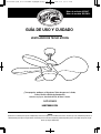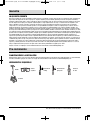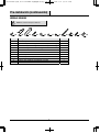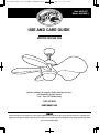
1
DPA12122002 新版 SIZE:216x280mm 80g模糙纸 单黑色 28P 骑马钉 2013-4-16
第 1/28页
Item #602-647
Model #36LGM-L
USE AND CARE GUIDE
MYRON CEILING FAN
Questions, problems, missing parts? Before returning to the store,
call Hampton Bay Customer Service
8 a.m. - 6 p.m., EST, Monday-Friday
1-877-527-0313
HAMPTONBAY.COM
THANK YOU
We appreciate the trust and confidence you have placed in Hampton Bay through the purchase of this ceiling fan. We strive to continually create
quality products designed to enhance your home. Visit us online to see our full line of products available for your home improvement needs. Thank
you for choosing Hampton Bay!
DPA12122002 新版 SIZE:216x280mm 80g模糙纸 单黑色 28P 骑马钉 2013-4-16
第 2/28页
Table of Contents
Table of Contents .......................................................... 2 Safety Information......................................................... 2 Warranty ......................................................................... 3 Pre-Installation .............................................................. 3 Planning Installation ................................................................3 Tools Required .........................................................................3 Hardware Included ...................................................................4 Package Contents ....................................................................5 Installation ..................................................................... 6 Operation ..................................................................... 12 Care and Cleaning ...................................................... 13 Troubleshooting .......................................................... 13 Safety Information
1.
All wiring must be in accordance with the National Electrical
Code ANSI/NFPA 70-1999 and local electrical codes.
Electrical installation should be performed by a qualified
licensed electrician.
2.
The outlet box and support structure must be securely
mounted and capable of reliably supporting a minimum of
35 lbs. (16 kg). Use only UL-listed outlet boxes marked “For
Fan Support.”
3.
Do not operate the reversing switch while the fan blades are
in motion. You must turn the fan off and stop the blades
before you reverse the blade direction.
4.
Avoid placing objects in the path of the fan blades.
5.
Electrical diagrams are for reference only. Light kits that are
not packed with the fan must be UL-listed and marked
suitable for use with the model fan you are installing.
Switches must be UL General Use Switches. Refer to the
instructions packaged with the light kits and switches for
proper assembly.
6.
After making electrical connections, spliced conductors
should be turned upward and pushed carefully up into the
outlet box. The wires should be spread apart with the
grounded conductor and the equipment-grounding
conductor on one side of the outlet box.
WARNING: To reduce the risk of electric shock, ensure
electricity has been turned off at the circuit breaker or fuse
box before beginning.
WARNING: To reduce the risk of personal injury, do not
bend the blade brackets (also referred to as flanges) during
assembly or after installation. Do not insert objects in the
path of the blades.
WARNING: To reduce the risk of fire or electric shock, do
not use this fan with any solid-state speed control device.
CAUTION: To reduce the risk of injury to person, the fan
must be mounted with a minimum of 7 feet clearance from
the trailing edge of the blades to the floor.
2
DPA12122002 新版 SIZE:216x280mm 80g模糙纸 单黑色 28P 骑马钉 2013-4-16
第 3/28页
Warranty
WHAT IS COVERED
The supplier warrants the fan motor to be free from defects in workmanship and material present at time of shipment from the factory for a
lifetime after the date of purchase by the original purchaser. The supplier also warrants that all other fan parts, excluding any glass or
acrylic blades, to be free from defects in workmanship and material at the time of shipment from the factory for a period of one year after
the date of purchase by the original purchaser. We agree to correct such defects without charge or at our option replace with a comparable
or superior model if the product is returned. To obtain warranty service, you must present a copy of the receipt as proof of purchase. All
costs of removing and reinstalling the product are your responsibility. Damage to any part such as by accident or misuse or improper
installation or by affixing any accessories, is not covered by this warranty. Because of varying climatic conditions this warranty does not
cover any changes in brass finish, including rusting, pitting, corroding, tarnishing, or peeling. Brass finishes of this type give their longest
useful life when protected from varying weather conditions. A certain amount of “wobble” is normal and should not be considered a defect.
Servicing performed by unauthorized persons shall render the warranty invalid. There is no other express warranty. Hampton Bay hereby
disclaims any and all warranties, including but not limited to those of merchantability and fitness for a particular purpose to the extent
permitted by law. The duration of any implied warranty which cannot be disclaimed is limited to the time period as specified in the express
warranty. Some states do not allow a limitation on how long an implied warranty lasts, so the above limitation may not apply to you. The
retailer shall not be liable for incidental, consequential, or special damages arising out of or in connection with product use or performance
except as may otherwise be accorded by law. Some states do not allow the exclusion of incidental or consequential damages, so the above
exclusion or limitation may not apply to you. This warranty gives specific legal rights, and you may also have other rights which vary from
state to state. This warranty supersedes all prior warranties. Shipping costs for any return of product as part of a claim on the warranty
must be paid by the customer.
Contact the Customer Service Team at 1-877-527-0313 or visit www.HamptonBay.com.
Pre-Installation
PLANNING INSTALLATION
Compare all parts with the Hardware Included and Package Contents sections in this manual. If any part is missing or damaged, do not
install this fan and contact the Customer Service Team at 1-877-527-0313 or visit www.HamptonBay.com.
TOOLS REQUIRED
Hammer
Safety
goggles
Phillips
screwdriver
Flathead
screwdriver
Wire cutters
Step
ladder
3
HAMPTONBAY.COM
Please contact 1-877-527-0313 for further assistance.
DPA12122002 新版 SIZE:216x280mm 80g模糙纸 单黑色 28P 骑马钉 2013-4-16
第 4/28页
Pre-Installation (continued)
HARDWARE INCLUDED
NOTE: Hardware not shown to actual size.
AA
BB
CC
DD
FF
EE
GG
Part
Description
Quantity
AA
Blade screw
21
BB
Downrod clip (preassembled to Downrod (E))
1
CC
Downrod pin (preassembled to Downrod (E))
1
DD
Collar screw (preassembled to Motor (D))
1
EE
Washer
2
FF
Star washer
2
GG
Lockwasher
2
HH
Mounting bracket screw
2
II
Canopy screw (preassembled to Mounting bracket (H))
2
JJ
Light kit screw (Preassembled to Motor (D))
3
KK
Wire connector
4
4
HH
II
JJ
KK
DPA12122002 新版 SIZE:216x280mm 80g模糙纸 单黑色 28P 骑马钉 2013-4-16
第 5/28页
Pre-Installation (continued)
PACKAGE CONTENTS
D
B
A
C
G
H
I
F
E
L
J
K
Part
Description
Quantity
A
Blade fix ring A
1
B
Fan blade
5
C
Blade fix ring B
1
D
Motor
1
E
Downrod
1
F
Canopy
1
G
Upper housing
1
H
Mounting bracket
1
I
Transmitter/Receiver
J
Light kit
1
K
Bulb
2
L
Glass shade
1
5
1 each
HAMPTONBAY.COM
Please contact 1-877-527-0313 for further assistance.
DPA12122002 新版 SIZE:216x280mm 80g模糙纸 单黑色 28P 骑马钉 2013-4-16
第 6/28页
Installation
1
2
Determining the mounting method
□
WARNING: To reduce the risk of fire, electric shock, or
personal injury, mount the fan to an outlet box marked
acceptable for fan support using the screws provided with
the outlet box. An outlet box commonly used for the support
of lighting fixtures may not be acceptable for fan support
and may need to be replaced. If in doubt, consult a qualified
electrician.
Attach each fan blade (B) to blade fix ring A (A) using blade
screws (AA). Tighten securely with a Phillips screwdriver.
AA
B
If your ceiling fan does not have an existing UL-listed mounting
box, then install one using the following instructions:
□ Disconnect the power by removing the fuses or turning off
the circuit breakers.
□ Secure the outlet box directly to the building structure. Use
the appropriate fasteners and materials. The outlet box and
its bracing must be able to fully support the weight of the
moving fan (at least 35 lbs.). Do not use a plastic outlet
box.
□ To hang your fan where there is an existing fixture but no
ceiling joist, you may need an installation hanger bar as
shown in the last figure.
A
Outlet Box
Outlet Box
Provide Strong
Support
Ceiling
Mounting
Plate
Recessed
Outlet Box
Attaching the blades to the blade
fix ring
Hanger Bar
Outlet Box
6
DPA12122002 新版 SIZE:216x280mm 80g模糙纸 单黑色 28P 骑马钉 2013-4-16
第 7/28页
Installation (continued)
3
□
□
□
4 Preparing the downrod
Attaching the blade assembly to
the motor
Place the blade assembly over the motor (D).
Place blade fix ring B (C) over the blade assembly (B).
Secure the blade fix ring B (C) and the blade assembly (B)
to the motor (D) using blade screws (AA).
□
□
Remove the downrod clip (BB) and downrod pin (CC) from
the downrod (E).
Thread the downrod (E) through the canopy (F) and upper
housing (G).
E
C
AA
BB
CC
B
F
D
G
E
7
HAMPTONBAY.COM
Please contact 1-877-527-0313 for further assistance.
DPA12122002 新版 SIZE:216x280mm 80g模糙纸 单黑色 28P 骑马钉 2013-4-16
第 8/28页
Installation (continued)
5
□
□
□
□
□
6 Installing the mounting bracket
Attaching the downrod assembly
to the motor
Loosen, but do not remove the collar screw (DD) on the
collar (1) of the motor (D).
Guide the downrod assembly into the collar (1) of the motor
(D). Ensure that all of the holes are in alignment.
Carefully insert the downrod pin (CC) through the holes in
the collar (1) and downrod (E).
Insert the downrod clip (BB) through the hole near the end
of the downrod pin (CC) until it snaps into its locked
position.
Re-tighten the collar screw (DD) on the collar (1) on top of
the motor (D).
□
H
G
EE
E
FF
BB
DD
Attach the mounting bracket (H) to the outlet box in the
ceiling using washers (EE), star washers (FF), lockwashers
(GG), and mounting bracket screws (HH). Tighten securely
with a Phillips screwdriver.
CC
GG
1
HH
B
8
DPA12122002 新版 SIZE:216x280mm 80g模糙纸 单黑色 28P 骑马钉 2013-4-16
第 9/28页
Installation (continued)
7
□
□
□
8
Installing the fan assembly and
receiver
Seat the hanger ball portion of the ball/downrod assembly
(E) in the mounting bracket socket. Ensure that the tab on
the mounting bracket (H) socket is properly seated in the
groove in the hanger ball.
Set the codes on the transmitter and receiver (I) by moving
the switches (1) up and down. Ensure that the transmitter
and receiver are set to the same code or the transmitter
will not work.
Slide the receiver (I) into position in the space between the
hanger ball portion of the downrod (E) and the mounting
bracket (H).
WARNING: To avoid possible electrical shock, be sure
electricity is turned off at the main fuse box before wiring.
If you are not sure the electrical box and fan are grounded,
contact a licensed electrician for advice. They must be
grounded for safe operation..
WARNING: Each wire nut (wire connector) supplied with
this fan is designed to accept up to one 12 gauge house
wire and two wires from the fan. If you have larger than 12
gauge house wiring or more than one house wire to connect
to the fan wiring, consult an electrician for the proper size
wire nuts to use..
□
1
□
Up
Down
Connecting the wires
On Dip
□
□
1 2 3 4
□
□
□
I
□
H
Connect the ground conductor of the 120-Volt supply (this
may be a bare wire or a wire with green colored insulation)
to the green ground lead(s) (PP) of the fan.
Connect the fan motor white wire (MM) to the receiver (I)
white wire (MM) using a wire connecting nut (KK).
Connect the fan motor black wire (LL) to the receiver (I)
black wire (LL) using a wire connecting nut (KK).
Connect the fan motor blue wire (OO) to the receiver (I) blue
wire (OO) using a wire connecting nut (KK).
Connect the receiver (I) black wire (NN) to the supply black
(hot) wire (LL) using a wire connecting nut (KK).
Connect the receiver (I) white wire (MM) to the supply white
wire (neutral) (MM) wire using a wire connecting nut (KK).
After connecting the wires, spread them apart so that the
green (PP) and white wires (MM) are one side of the outlet
box (1) and the black wire (LL) is on the other side.
Turn the wire connecting nuts upward, and carefully push
the wiring into the outlet box (1).
LL
MM
PP
1
E
NN
MM
MM
I
OO
LL
9
HAMPTONBAY.COM
Please contact 1-877-527-0313 for further assistance.
DPA12122002 新版 SIZE:216x280mm 80g模糙纸 单黑色 28P 骑马钉 2013-4-16
第 10/28页
Installation (continued)
9
□
□
□
Attaching the canopy to the
mounting bracket
I
Remove one of the preassembled canopy screws (II) from
the end of the mounting bracket (H). Loosen, but do not
remove, the second canopy screw (II).
Raise the canopy (F) up to the ceiling and slide the slotted
hole in the canopy through the loosened canopy screw (II)
and twist the canopy (F) to lock it in place on the screw (II).
Reattach the other canopy screw (II) to the canopy (F) and
tighten both screws securely with a Phillips screwdriver.
H
II
II
H
F
II
II
10 Attaching the light kit to the fan
□
□
□
□
□
Loosen, but do not remove, two of the light kit screws (JJ)
attached to the light kit plate (1) portion of the motor (D).
Remove the third light kit screw (JJ) from the light kit plate
(1) portion of the motor (D).
Raise the light kit (J) up to the motor (D) and connect the
two wires (1) from the light kit (J) to the two wires (2) from
the motor (D). Ensure that the colors of the wires match and
that they are securely connected.
Tuck the wires into the motor (D), align the slots in the light
kit (J) with the loosened light kit screws (JJ), and twist to
lock in place.
Reinstall the previously-removed light kit screw (JJ) and
securely tighten all light kit screws (JJ) with a Phillips
screwdriver.
1
JJ
D
JJ
D
JJ
2
1
J
10
DPA12122002 新版 SIZE:216x280mm 80g模糙纸 单黑色 28P 骑马钉 2013-4-16
第 11/28页
Installation (continued)
11
□
□
Installing the bulbs and glass
shade
Install the two bulbs (K) into the sockets on the light kit (J).
Raise the glass shade (L) up to the light kit (J), align the tabs
in the light kit (J) with the slots on the shade (L) and twist
clockwise to secure the shade (L) to the light kit (J).
K
J
L
11
HAMPTONBAY.COM
Please contact 1-877-527-0313 for further assistance.
DPA12122002 新版 SIZE:216x280mm 80g模糙纸 单黑色 28P 骑马钉 2013-4-16
第 12/28页
Operation
1
2 Using the remote control
Setting the blade direction
The slide switch (1) on the motor (D) controls the direction of the
blades: forward (switch right) or reverse (switch left).
□ Warm weather – (Forward) A downward air flow creates a
cooling effect. This allows you to set your air conditioner on
a higher setting without affecting your comfort.
□ Cool weather – (Reverse) An upward air flow moves warm
air off the ceiling area. This allows you to set your heating
unit on a lower setting without affecting your comfort.
□
(1) On/Off: Press and release immediately to turn the light
on or off.
(2) Dim: Press and hold to dim or brighten lights to the
desired level and release. (Only for the tungsten bulb.)
(3) Off: Turn off the ceiling fan.
(4) Hi:Turn on the fan at high speed.
(5) Med: Turn on the fan at medium speed.
(6) Low: Turn on the fan at low speed.
3
6
1
D
4
5
2
1
12
DPA12122002 新版 SIZE:216x280mm 80g模糙纸 单黑色 28P 骑马钉 2013-4-16
第 13/28页
Care and Cleaning
WARNING: Make sure the power is off at the electrical
panel box before you attempt any repairs.
□
Because of the fan’s natural movement, some connections may become loose. Check the support connections, brackets, and blade
attachments twice a year. Make sure they are secure. (It is not necessary to remove the fan from the ceiling.)
□
Clean your fan periodically to help maintain its new appearance over the years. Use only a soft brush or lint-free cloth to avoid
scratching the finish. The plating is sealed with a lacquer to minimize discoloration or tarnishing. Do not use water when cleaning.
This could damage the motor, or the wood, or possibly cause an electrical shock.
□
You can apply a light coat of furniture polish to the wood blades for additional protection and enhanced beauty. Cover small
scratches with a light application of shoe polish.
□
There is no need to oil your fan. The motor has permanently lubricated bearings.
Troubleshooting
Problem
The fan will not start.
The fan is noisy.
The fan wobbles.
Solution
□ Check the main and branch circuit fuses or breakers.
□
Check the line wire connections to the fan and switch wire connections in the switch housing.
□
Check the battery in the remote control.
□
Ensure you are in the normal range of 10-20 feet.
□
Turn the power off and ensure that the dip switch settings are the same on the remote control
and receiver.
□
Ensure all motor housing screws are snug.
□
Ensure the screws that attach the fan blade bracket to the motor hub are tight.
□
Ensure the wire nut connections are not rattling against each other or the interior wall of the
switch housing.
□
Allow a 24-hour “breaking in” period. Most noises associated with a new fan disappear during
this time.
□
If you are using the Ceiling Fan light kit, ensure the screws securing the glassware are tight.
Check that the light bulbs are also secure.
□
Ensure the canopy is a short distance from the ceiling. It should not touch the ceiling.
□
Ensure your outlet box is secure and rubber isolator pads were used between the mounting plate
and outlet box.
□
Check that all blade and blade arm screws are secure.
□
Most fan wobble problems are caused when blade levels are unequal. Check this level by
selecting a point on the ceiling above the tip of one of the blades. Measure from a point on the
center of the blade to the point on the ceiling. Rotate the fan until the next blade is positioned for
measurement, and measure from the same point on each blade to the ceiling. Repeat for each
blade. Any measurement deviation should be within 1/8 in. Run the fan for ten minutes.
□
Use the enclosed blade balancing kit if the blade wobble is still noticeable.
13
HAMPTONBAY.COM
Please contact 1-877-527-0313 for further assistance.
DPA12122002 新版 SIZE:216x280mm 80g模糙纸 单黑色 28P 骑马钉 2013-4-16
第 14/28页
Questions, problems, missing parts? Before returning to the store,
call Hampton Bay Customer Service
8 a.m. - 6 p.m., EST, Monday-Friday
1-877-527-0313
HAMPTONBAY.COM
Retain this manual for future use.
DPA12122002 新版 SIZE:216x280mm 80g模糙纸 单黑色 28P 骑马钉 2013-4-16
第 15/28页
Núm. de artículo 602-647
Núm. de modelo 36LGM-L
GUÍA DE USO Y CUIDADO
VENTILADOR DE TECHO MYRON
¿Tiene preguntas, problemas, o faltan piezas? Antes de regresar a la tienda,
llame al Servicio a Clientes de Hampton Bay
entre 8 a.m. y 6 p.m., hora local del Este, de lunes a viernes
1-877-527-0313
HAMPTONBAY.COM
GRACIAS
Agradecemos la confianza que ha puesto en Hampton Bay a través de la compra de este ventilador de techo. Nos esforzamos por crear continuamente productos de
calidad diseñados para mejorar su hogar. Visítenos en internet para ver nuestra línea completa de productos disponibles para sus necesidades de mejorar su hogar.
¡Gracias por elegir a Hampton Bay!
DPA12122002 新版 SIZE:216x280mm 80g模糙纸 单黑色 28P 骑马钉 2013-4-16
第 16/28页
Tabla de contenido
Tabla de contenido ....................................................... 2
Información de seguridad ............................................ 2
Garantía .......................................................................... 3
Pre-instalación .............................................................. 3
Planificación de la instalación .................................................3
Herramientas requeridas .........................................................3
Herraje incluido ........................................................................4
Contenido del paquete .............................................................5
Instalación ..................................................................... 6
Operación .................................................................... 12
Cuidado y limpieza ..................................................... 13
Resolución de fallas ................................................... 13
Información de seguridad
1.
Todo el cableado debe estar de acuerdo con el Código Eléctrico
Nacional, ANSI/NFPA 70-1999 y los códigos eléctricos locales. La
instalación debe ser hecha por un electricista calificado autorizado.
ADVERTENCIA: Para reducir el riesgo de choque eléctrico,
antes de comenzar asegúrese de que la electricidad haya sido
desconectada en el interruptor de circuito o la caja de fusibles.
2.
La caja de salida y la estructura de soporte deben estar montadas
con seguridad y ser capaces de soportar de manera fiable un
mínimo de 35 libras. (16 kg). Use solamente cajas de salida
listadas UL marcadas “Para soporte de ventilador”.
ADVERTENCIA: Para reducir el riesgo de lesiones personales,
no doble los soportes de las aspas (también llamados bridas)
durante el ensamblaje o después de la instalación. No inserte
objetos en el paso de las aspas.
3.
No opere el interruptor de reversa mientras las aspas del ventilador
estén en movimiento. Debe apagar el ventilador y detener las
aspas antes de invertir la dirección de las aspas.
ADVERTENCIA: Para reducir el riesgo de incendio o choque
eléctrico, no use este ventilador con ningún dispositivo de control
de velocidad de estado sólido.
4.
Evite colocar objetos en el paso de las aspas del ventilador.
5.
Los diagramas eléctricos son solamente para referencia. Los
juegos de lámparas que no están empacados con el ventilador
deben ser listados UL y marcados como adecuados para uso con el
ventilador modelo que está instalando. Los interruptores deben ser
Interruptores de Uso General UL. Consulte las instrucciones que
vienen con los juegos de lámparas e interruptores para un montaje
apropiado.
PRECAUCIÓN: Para reducir el riesgo de lesiones personales, el
ventilador el ventilador debe estar montado con un mínimo de 7
pies de espacio libre desde el borde posterior de las aspas hasta el
piso.
6.
Después de hacer conexiones eléctricas, los conductores
empalmados deben ser girados hacia arriba y empujados con
cuidado hacia adentro de la caja de salida. Los cables deben estar
separados con el conductor de puesta a tierra y el conductor de
puesta a tierra del equipo en un lado de la caja de salida.
2
DPA12122002 新版 SIZE:216x280mm 80g模糙纸 单黑色 28P 骑马钉 2013-4-16
第 17/28页
Garantía
LO QUE ESTÁ CUBIERTO
El proveedor garantiza que el motor del ventilador está libre de defectos en materiales y mano de obra presentes en el momento del envío de la fábrica por
un periodo de vida después de la fecha de compra por el comprador original. El proveedor también garantiza que todas las otras piezas del ventilador,
excluyendo cualquier aspa de vidrio o acrílico, están libres de defectos en materiales y mano de obra en el momento del envío de la fábrica por un periodo
de un año después de la compra por el comprador original. Aceptamos corregir cualquier defecto sin cargos o a nuestra discreción reemplazar con un
modelo comparable o superior si el producto es devuelto. Para obtener el servicio de garantía, debe presentar una copia del recibo como prueba de
compra. Todos los costos por retirar o reinstalar el producto son responsabilidad del comprador. Los daños a cualquier pieza por accidente o mal uso o
instalación inapropiada o por la fijación de cualquier accesorio, no están cubiertos por la garantía. Debido a las condiciones climáticas variables, esta
garantía no cubre ningún cambio en el acabado de latón, incluyendo herrumbre, picaduras, corrosión, deslustrado o descamación. Los acabados de latón
de este tipo dan su vida útil más larga cuando se protegen de las condiciones climáticas variables. Es normal una cierta cantidad de “bamboleo” y no debe
ser considerado un defecto. El mantenimiento realizado por personas no autorizadas anulará la garantía. No hay otra garantía expresa. Hampton Bay por la
presente renuncia a cualquiera y todas las garantías, incluyendo pero no limitadas a garantías de comercialización e idoneidad para un propósito particular
en la medida permitida por la ley. La duración de cualquier garantía implícita que no puede ser denegada está limitada al periodo de tiempo que se
especifica en la garantía expresa. Algunos estados no permiten limitaciones sobre cuánto debe durar una garantía, por lo tanto las limitaciones anteriores
podrían no aplicar a usted. El fabricante no será responsable de daños incidentales, consecuentes, o daños especiales que surjan de o con respecto al uso
o rendimiento del producto excepto como pueda ser acordado de otra manera por la ley. Algunos estados no permiten la exclusión o la limitación de daños
incidentales o consecuentes; por lo tanto, las limitaciones y exclusiones anteriores podrían no aplicar a usted. Esta garantía le otorga derechos legales
específicos, y también puede tener otros derechos que varían de un estado a otro. Esta garantía reemplaza todas las garantías anteriores. Los costos de
envío por cualquier devolución de producto como parte de un reclamo sobre la garantía deben ser pagados por el cliente.
Póngase en contacto con el Equipo de Servicio al Cliente llamando al 1-877-527-0313 o visite www.HamptonBay.com.
Pre-instalación
PLANIFICACIÓN DE LA INSTALACIÓN
Compare todas las piezas con las secciones de Herraje incluido y Contenido del paquete en este manual. Si hace falta alguna pieza o se encuentra dañada,
no instale este ventilador y póngase en contacto con el equipo de Servicio al Cliente al 1-877-527-0313 o visite www.HamptonBay.com.
HERRAMIENTAS REQUERIDAS
Martillo
Gafas de
seguridad
Destornillador
Phillips
Destornillador de
punta plana
Cortadores
de cable
Escalerilla
3
HAMPTONBAY.COM
Para obtener asistencia, póngase en contacto llamando al 1-877-527-0313.
DPA12122002 新版 SIZE:216x280mm 80g模糙纸 单黑色 28P 骑马钉 2013-4-16
第 18/28页
Pre-instalación (continuación)
HERRAJE INCLUIDO
NOTA: No se muestra el herraje en el tamaño real.
AA
Pieza
BB
CC
DD
EE
FF
Descripción
HH
GG
Cantidad
AA
Tornillo de aspa
21
BB
Gancho de vástago de extensión (preensamblado a vástago de extensión (E))
1
CC
Pasador de vástago de extensión (preensamblado a vástago de extensión (E))
1
DD
Tornillo de collarín (preensamblado a motor (D))
1
EE
Arandela
2
FF
Arandela de estrella
2
GG
Arandela de seguridad
2
HH
Tornillo de soporte de montaje
2
II
Tornillo de dosel (preensamblado a soporte de montaje (H))
2
JJ
Tornillo de juego de lámparas (preensamblado a motor (D))
3
KK
Conector de cable
4
4
II
JJ
KK
DPA12122002 新版 SIZE:216x280mm 80g模糙纸 单黑色 28P 骑马钉 2013-4-16
第 19/28页
Pre-instalación (continuación)
CONTENIDO DEL PAQUETE
D
B
A
C
G
E
H
I
F
L
J
K
Pieza
Descripción
Cantidad
A
Aro de fijación de aspa A
1
B
Aspa del ventilador
5
C
Aro de fijación de aspa B
1
D
Motor
1
E
Vástago de extensión
1
F
Dosel
1
G
Carcasa superior
1
H
Soporte de montaje
1
I
Transmisor/Receptor
1 de cada una
J
Juego de lámparas
1
K
Bombilla
2
L
Pantalla de vidrio
1
5
HAMPTONBAY.COM
Para obtener asistencia, póngase en contacto llamando al 1-877-527-0313.
DPA12122002 新版 SIZE:216x280mm 80g模糙纸 单黑色 28P 骑马钉 2013-4-16
第 20/28页
Instalación
1
2
Determinación del método
de montaje
□
ADVERTENCIA: Para evitar el riesgo de incendio, choque
eléctrico o lesiones a las personas, monte el ventilador en una caja
de salida marcada aceptable para soporte de ventilador usando los
tornillos proporcionados con la caja de salida. Una caja de salida
usada comúnmente como soporte de luminarias puede no ser
aceptable para soporte de ventilador y puede necesitar ser
reemplazada. Si tiene dudas, consulte con un electricista
calificado.
B
A
Box
CajaOutlet
de salida
Caja
de salida
Outlet
Box
Proporcione
soporte
Provide Strong
fuerte
Support
Recessed
Instale cada aspa del ventilador (B) al aro de fijación de aspa A (A)
usando los tornillos de aspa (AA). Apriete con seguridad con un
desarmador Phillips.
AA
Si su ventilador de techo no tiene una caja de montaje existente listada UL,
entonces instale una empleando las siguientes instrucciones:
□ Desconecte la energía retirando los fusibles o apagando los
interruptores de circuito.
□ Asegure la caja de salida directamente a la estructura del edificio.
Use los sujetadores y materiales apropiados. La caja de salida y
su abrazadera deben de ser capaces de soportar por completo el
peso móvil del ventilador (al menos 35 lbs.) No use caja de salida
plástica.
□ Para colgar su ventilador donde ya hay una luminaria pero no una
viga de techo, puede necesitar un barra colgador como se
muestra en la última figura.
Ceiling
CajaOutlet
de salida
Box
ahuecada
Instalación de las aspas al aro de
fijación de las aspas
Placa
de montaje
Mounting
del
techo
Plate
Barra
colgador
Hanger
Bar
Caja
de salida
Outlet
Box
6
DPA12122002 新版 SIZE:216x280mm 80g模糙纸 单黑色 28P 骑马钉 2013-4-16
第 21/28页
Instalación (continuación)
3
□
□
□
4
Instalación del ensamblaje de las
aspas en el motor
Coloque el ensamblaje de las aspas sobre el motor (D).
Coloque el aro de fijación de las aspas B (C) sobre el ensamblaje
de las aspas (B).
Asegure el aro de fijación de las aspas B (C) y el ensamblaje de
las aspas (B) en el motor (D) usando los tornillos de aspas (AA).
□
□
Preparación del vástago de
extensión
Retire el gancho del vástago de extensión (BB) y el pasador del
vástago de extensión (CC) del vástago de extensión (E).
Ensarte el vástago de extensión (E) a través del dosel (F) y la
carcasa superior (G).
E
C
AA
BB
CC
B
F
D
G
E
7
HAMPTONBAY.COM
Para obtener asistencia, póngase en contacto llamando al 1-877-527-0313.
DPA12122002 新版 SIZE:216x280mm 80g模糙纸 单黑色 28P 骑马钉 2013-4-16
第 22/28页
Instalación (continuación)
5
□
□
□
□
□
6 Instalación del soporte de montaje
Instalación del ensamblaje del
vástago de extensión en el motor
Afloje, pero no retire el tornillo de collarín (DD) en el collarín (1)
del motor (D).
Guíe el ensamblaje del vástago de extensión en el collarín (1) del
motor (D). Asegúrese de que todos los agujeros estén alineados.
Cuidadosamente, inserte el pasador del vástago de extensión (E) a
través de los agujeros en el collarín (1) y el vástago de extensión
(E).
Inserte el gancho del vástago de extensión (BB) a través del
agujero cercano al extremo del pasador del vástago de extensión
(CC) hasta que encaje en su posición bloqueada.
Apriete de nuevo el tornillo del collarín (DD) en el collarín (1) en la
parte superior del motor (D).
□
Instale el soporte de montaje (H) en la caja de salida en el techo
usando arandelas (EE), arandelas de estrella (FF), arandelas de
seguridad (GG) y tornillos del soporte del montaje (HH). Apriete con
seguridad con un desarmador Phillips.
H
G
EE
E
FF
BB
DD
GG
CC
1
HH
B
8
DPA12122002 新版 SIZE:216x280mm 80g模糙纸 单黑色 28P 骑马钉 2013-4-16
第 23/28页
Instalación (continuación)
7
□
□
□
8
Instalación del ensamblaje del
ventilador y el receptor
Asiente la parte esférica del colgador del ensamblaje
esfera/vástago de extensión (E) en el cubo del soporte de
montaje. Asegúrese de que la pestaña en el cubo del soporte de
montaje (H) esté apropiadamente asentada en la muesca de la
esfera del colgador.
Ajuste los códigos en el transmisor y receptor (I) moviendo los
interruptores (1) hacia arriba y hacia abajo. Asegúrese de que el
transmisor y receptor estén ajustados al mismo código o el
transmisor no funcionará.
Deslice el receptor (I) a su posición en el espacio entre la parte
esférica del colgador del vástago de extensión (E) y el soporte de
montaje (H).
ADVERTENCIA: Para evitar posibles choques eléctricos,
asegúrese de que la electricidad esté desconectada en la caja de
fusibles principal antes del cableado.Si no está seguro de que la
caja eléctrica y el ventilador están conectados a tierra, póngase en
contacto con un electricista calificado para que lo aconseje. Deben
estar conectados a tierra para una operación segura.
ADVERTENCIA: Cada tuerca de cable (conector de cable)
suministrada con este ventilador está diseñada para aceptar hasta
un cable calibre 12 y dos cables del ventilador. Si tiene un cableado
más grande de calibre 12 o más de un cableado para conectar al
cableado del ventilador, consulte a un electricista sobre el tamaño
adecuado de las tuercas de cableado que debe usar.
□
1
□
Arriba
Up
Down
Abajo
Conexión de los cables
Dip
EnOn
pendiente
□
1 2 3 4
□
□
□
□
I
□
Conecte el conductor de tierra del suministro de 120-Voltios
(puede ser un cable desnudo o un cable con aislamiento de color
verde) al cable de tierra verde (PP) del ventilador.
Conecte el cable blanco del motor del ventilador (MM) al cable
blanco (MM) del receptor (I) usando una tuerca de conexión de
cable (KK).
Conecte el cable negro del motor del ventilador (LL) al cable negro
(LL) del receptor (I) usando una tuerca de conexión de cable (KK).
Conecte el cable azul del motor del ventilador (OO) al cable azul
(OO) del receptor (I) usando una tuerca de conexión de cable (KK).
Conecte el cable negro (NN) del receptor (I) al cable negro (de
carga) de suministro (LL) usando una tuerca de conexión de cable
(KK).
Conecte el cable blanco (MM) del receptor (I) al cable blanco (neutro)
de suministro (MM) usando una tuerca de conexión de cable (KK).
Después de conectar los cables, sepárelos de modo que los
cables verde (PP) y blanco (MM) estén a un lado de la caja de
salida (1) y el cable negro (LL) esté en el otro lado.
Gire las tuercas conectoras de cable hacia arriba y empuje con
cuidado el cableado dentro de la caja de salida (1).
LL
H
MM
PP
1
E
NN
MM
MM
I
OO
LL
9
HAMPTONBAY.COM
Para obtener asistencia, póngase en contacto llamando al 1-877-527-0313.
DPA12122002 新版 SIZE:216x280mm 80g模糙纸 单黑色 28P 骑马钉 2013-4-16
第 24/28页
Instalación (continuación)
9
□
□
□
Instalación del dosel en el soporte
de montaje
I
Retire uno de los tornillos preensamblados (II) del dosel del
extremo del soporte de montaje (H). Afloje, pero no retire el
segundo tornillo (II) del dosel.
Levante el dosel (F) hasta al techo y deslice el agujero ranurado en
el dosel a través del tornillo aflojado (II) del dosel y gire el dosel (F)
para bloquearlo en su lugar en el tornillo (II).
Instale de nuevo el otro tornillo del dosel (II) en el dosel (F) y apriete
ambos tornillos con seguridad con un destornillador Phillips.
II
H
II
H
F
II
II
10
□
□
□
□
□
Instalación del juego de lámparas
en el ventilador
Afloje pero no retire dos de los tornillos del juego de lámparas (JJ)
instalados en la parte de la placa (1) del juego de lámparas del
motor (D).
Retire el tercer tornillo (JJ) del juego de lámparas de la parte de la
placa (1) del juego de lámparas del motor (D).
Levante el juego de lámparas (J) hasta el motor (D) y conecte los
dos cables (1) del juego de lámparas (J) a los dos cables (2) del
motor (D). Asegúrese de que los colores de los cables coincidan y
que estén conectados con seguridad.
Inserte los cables en el motor (D), alinee las ranuras en el juego de
lámparas (J) con los tornillos (JJ) flojos del juego de lámparas y
gire para bloquear en su lugar.
Instale de nuevo el tornillo (JJ) del juego de lámparas
anteriormente retirado y apriete con seguridad todos los tornillos
(JJ) del juego de lámparas con un destornillador Phillips.
1
JJ
D
JJ
D
JJ
2
1
J
10
DPA12122002 新版 SIZE:216x280mm 80g模糙纸 单黑色 28P 骑马钉 2013-4-16
第 25/28页
Instalación (continuación)
11
□
□
Instalación de las bombillas y la
pantalla de vidrio
Instale las dos bombillas (K) en los receptáculos del juego de
lámparas (J).
Levante la pantalla de vidrio (L) hasta el juego de lámparas (J),
alinee las pestañas en el juego de lámparas (J) con las ranuras en
la pantalla (L) y gire hacia la derecha para asegurar la pantalla (L)
en el juego de lámparas (J).
K
J
L
11
HAMPTONBAY.COM
Para obtener asistencia, póngase en contacto llamando al 1-877-527-0313.
DPA12122002 新版 SIZE:216x280mm 80g模糙纸 单黑色 28P 骑马钉 2013-4-16
第 26/28页
Operación
1
2 Uso del control remoto
Ajuste de la dirección de las
aspas
El interruptor corredizo (1) en el motor (D) controla la dirección de las
aspas: hacia adelante (interruptor derecho) o reversa (interruptor
izquierdo).
□ Clima cálido – (Hacia adelante) Un flujo de aire hacia abajo crea un
efecto de enfriamiento. Esto le permite ajustar su acondicionador de
aire a un ajuste más alto sin afectar su comodidad.
□ Clima fresco– (Reversa) Una corriente de aire hacia arriba hace salir
el aire caliente del área del techo. Esto le permite ajustar su unidad de
calefacción a un ajuste más bajo sin afectar su comodidad.
□
(1) Encendido/Apagado: Presione y suelte de inmediato para
encender o apagar la luz.
(2) Atenuación: Presione y sostenga para atenuar o mejorar el
brillo al nivel deseado y suelte. (Solamente para bombillas de
Tungsteno.)
(3) Apagado: Apague el ventilador de techo.
(4) Alta: Enciende el ventilador a velocidad alta.
(5) Media: Enciende el ventilador a velocidad media.
(6) Baja: Enciende el ventilador a velocidad baja.
3
6
1
D
4
5
2
1
12
DPA12122002 新版 SIZE:216x280mm 80g模糙纸 单黑色 28P 骑马钉 2013-4-16
第 27/28页
Cuidado y limpieza
ADVERTENCIA: Asegúrese de que la energía esté desconectada
en la caja del panel eléctrico antes de intentar cualquier reparación.
□
Debido al movimiento natural del ventilador, algunas conexiones se pueden aflojar. Revise las conexiones del soporte, soportes y acoplamientos de
las aspas dos veces al año. Asegúrese de que estén seguras. (No es necesario retirar el ventilador del techo.)
□
Limpie su ventilador periódicamente para ayudar a mantener su apariencia nueva con el paso de los años. Use solamente un cepillo suave o paño
sin pelusa para evitar rayar el acabado. El enchapado está sellado con una laca para minimizar la decoloración o el deslustrado. No use agua
cuando limpie. Esto podría dañar el motor, o la madera, o causar posiblemente un choque eléctrico.
□
Puede aplicar una capa ligera de cera para muebles a las aspas de madera para protección adicional y belleza mejorada. Cubra las rayas pequeñas
con una aplicación ligera de betún para calzado.
□
No hay necesidad de aceitar su ventilador. El motor tiene cojinetes lubricados permanentemente.
Resolución de fallas
Problema
El ventilador no arranca.
El ventilador hace ruido.
El ventilador bambolea.
Solución
□
Revise los fusibles o disyuntores del circuito principal y derivado.
□
Revise las conexiones del cable de línea al ventilador y las conexiones del cable del interruptor en la
carcasa del interruptor.
□
Revise la batería en el control remoto.
□
Asegúrese de estar en el rango normal de 10-20 pies.
□
Apague la energía y asegúrese de que los ajustes del interruptor de atenuación sean los mismos en el
control remoto y el receptor.
□
Asegúrese de que todos los tornillos de la carcasa del motor estén ajustados.
□
Asegúrese de que los tornillos que sujetan el soporte de las aspas del ventilador al núcleo del motor estén
apretados.
□
Asegúrese de que las conexiones de la tuerca del cable no golpeen entre sí o con la pared interior de la
carcasa del interruptor.
□
Permita un periodo de “rodaje” de 24 horas. La mayoría de ruidos asociados a un ventilador nuevo
desaparecen durante este tiempo.
□
Si está usando un juego de lámparas de ventilador de techo, asegúrese de que los tornillos que aseguran la
cristalería estén apretados. Compruebe que las bombillas estén también seguras.
□
Asegúrese de que el dosel esté a una corta distancia del techo. No debe tocar el techo.
□
Asegúrese de que la caja de salida esté segura y que las almohadillas del aislante de goma fueron usadas
entre la placa de montaje y la caja de salida.
□
Compruebe que todos los tornillos de las aspas y del brazo de las aspas estén seguros.
□
La mayoria de problemas de bamboleo ocurren cuando los niveles de las aspas son desiguales. Compruebe
este nivel seleccionando un punto en el techo sobre la punta de una de las aspas. Mida desde un punto en
el centro del aspa hasta el punto en el techo. Gire el ventilador hasta que la siguiente aspa esté ubicada
para medición, y mida desde el mismo punto en cada aspa al techo. Repita para cada aspa. Cualquier
desviación de la medida debe estar dentro de 1/8 pulg. Haga funcionar el ventilador durante diez minutos.
□
Use el juego equilibrante de aspas incluido si todavía se observa el bamboleo de las aspas.
13
HAMPTONBAY.COM
Para obtener asistencia, póngase en contacto llamando al 1-877-527-0313.
DPA12122002 新版 SIZE:216x280mm 80g模糙纸 单黑色 28P 骑马钉 2013-4-16
第 28/28页
¿Tiene preguntas, problemas, o faltan piezas? Antes de regresar a la tienda,
llame al Servicio a Clientes de Hampton Bay
entre 8 a.m. y 6 p.m., hora local del Este, de lunes a viernes
1-877-527-0313
HAMPTONBAY.COM
Conserve este manual para uso futuro.
DPA12122002