Transcript
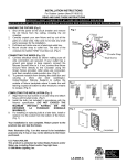
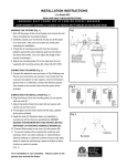
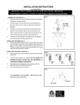
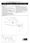
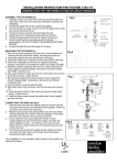
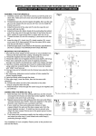
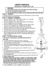
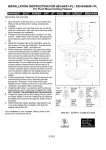
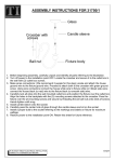
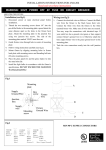
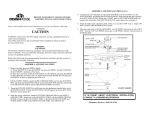
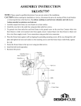
INSTALLATION INSTRUCTIONS
For Model 8952/8953
READ AND SAVE THESE INSTRUCTIONS
WARNING!
S H U T P O W E R O F F AT F U S E O R C I R C U I T B R E A K E R .
HANGING THE FIXTURE (Fig. 1)
1. Shut off the power at the circuit breaker and remove old fixture,
Fig.1
including the crossbar.
2. Carefully unpack your new fixture and lay out all the parts on a
clear area. Take care not to lose any small parts necessary for
installation.
3. Thread the 2 Mounting screws
(E) to the mounting
strap(C),(You can adjust the length of the screws if necessary.)
4. Attach the mounting strap(C)to the outlet box (A) (not
supplied)by using the 2 screws(B) provided with the Outlet Box
(A).
5. CONNECTING THE WIRES (Fig. 2)
At the point, connect the electrical wires as follows:
Connect the black wire from the fixture to the black (hot) house
wire. Connect the white wire from the fixture to the white
(neutral) house wire. Make sure all wire nuts are secured. You
may wrap the connections with electrical tape. If your outlet has
a ground wire (green or bare copper), connect fixture’s ground
wire to it. Otherwise, connect fixture’s ground wire directly to the
Fig. 2
FIXTURE
WIRES
Black or
Smooth
FIXTURE
WIRES
White or
Ribbed
FIXTURE
WIRES
Bare
Copper
(Ground)
mounting strap by using the green screw provided. Tuck the
wire connections neatly into the junction box.
HOUSE
WIRES
Black
(Hot)
6. Place fixture (G) over the two Mounting screws (E) from the
mounting strap (B) and secure with the 2 cap nuts (F).
HOUSE
WIRES
White
(Neutral)
HOUSE
WIRES
Green or
Bare
Copper
(Ground)
7. To prevent moisture from entering the outlet box and causing a
short, use clear caulking (i.e. Indoor/outdoor silicon sealant) to
Fig. 3
outline the outside of fixture backplate where it meets the wall
leaving a space at the bottom to allow moisture a means to
escape . (Fig.3)
8. Install bulbs. (Type-B. not supplied).
9. Put the cage (H) to the fixture (G) carefully, then secure with the
hex nut (M) and the finial (N). (Fig.1)
10. Turn on the power at fuse or circuit box.
DO NOT EXCEED THE MAXIMUM WATTAGE RATING!
Your installation is now complete. Return power to the
junction box and test the fixture.
Caulking
Backplate