Transcript
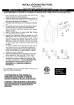
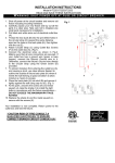
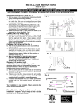
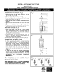
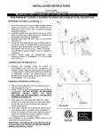
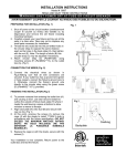
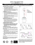
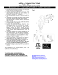
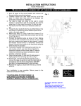
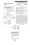
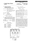
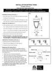
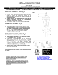
INSTALLATION INSTRUCTIONS
Model #8276-L
W AR N IN G !
READ AND SAVE THESE INSTRUCTIONS
S H U T P O W E R O F F AT F U S E O R C I R C U I T B R E A K E R .
AVERTISSEMENT! COUPER LE COURANT AU NIVEAU DES FUSIBLES OU DU DISJONCTEUR.
PREPARING FOR INSTALLATION (Fig.1)
Fig. 1
1. Shut off power at the circuit breaker and remove the old
fixture including the mounting hardware.
2. Carefully unpack your new fixture and lay out all the
parts in a clear area. Take care not to misplace any
small parts necessary for installation.
CONNECTING THE WIRES (Fig.3)
3. Pull the black, white and ground wires out of post (A).
4. While supporting the fixture, connect electrical wires. If
your post has a ground wire (green or bare copper),
connect the fixture ground wire to it. If not, consult your
electrician for proper grounding. After wires are
connected, tuck them carefully inside the post cup (C).
5. Align the lantern with post (A) and secure with screws
(B). (Fig.1&2)
6. Bulb (F) information (1 x AC LED 10W
included.)
(DO NOT EXCEED THE MAXIMUM
WATTAGE RATING) (NE PAS DEPASSER LA
PUISSANCE NOMINALE MAXIMALE!)
Replacing LED module (Fig.3)
10.
甲、
乙、
The LED module can be replaced by a qualified electrician
without cutting of wire and without damage to any decorative
element to which the fixture is attached. See installation steps for
more details (Fig.3).
a. Shut off power, remove the top cover by loosening screws (E)
(Fig.1), then remove aluminum panel (L) by loosening screws
(M) from the fixture cage (D).
b. Remove wire nuts (K), remove screws (O) and carefully
remove LED module (F) for re-lamping. Note: The LED
module should be provided by a specified supplier.
c. For better heat dissipation the LED module (F) should be
installed with the heat transfer material (R) when re-lamping.
F ig.2
HOUSE
WI RES
BLACK
( HOT)
HOUSE
WI RES
WHI TE
( NEUTRAL)
HOUSE
WI RES
GREEN OR
BARE COPPER( GROUND)
Fig. 3
R
(Graphite sheet)
Your installation is now complete. Return power to the outlet
box and test the fixture.
Note: Illustration (Fig.1) on this manual is for
installation purposes only. It may or may not be
identical to the fixture purchased.
FI XTURE
WI RES
GREEN OR
BARE
COPPER
( GROUND)
FI XTURE
WI RES
WHI TE
FI XTURE
WI RES
BLACK
Q(Glass)
P(Module ring)
K
L
M
F (LED module)
O(Module screws)