Transcript
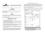
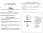
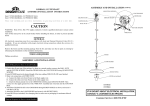
8.
FLUORESCENT FLUSH MOUNT FIXTURE ASSEMBLY &
INSTALLATION INSTRUCTIONS
Please read carefully and save this instruction sheet, as you may need it at a later
date.
CAUTION
Turn off the main power at the circuit breaker before installing the fixture, in order to
prevent possible shock.
GENERAL
All electrical connections must be in accordance with local and National Electrical
Code (N.E.C.) standards. If you are unfamiliar with proper electrical wiring
connections obtain the services of a qualified electrician.
Carefully tuck all wire connections into the FIXTURE BODY(10). Replace the
BALLAST COVER(16) and secure it in place using the BALLAST COVER
SCREWS(21).
9. Insert FLUORESCENT BULBS(14) into the provided LAMP SOCKETS(13).
Turn each FLUORESCENT BULB ¼ turn, until there is a click. Be sure to use
the lamp type and wattage specified on the lamp replacement label.
10. Re-attach the FRAME(19) and the ACRYLIC LENS(17) to the FIXTURE
BODY(10). (NOTE: For ease of installation, a SUPPORT PIN(22) is provided
at one end of the FRAME(19). During this step, angle this end of the
FRAME(19) toward the end of the FIXTURE BODY(10) with the SUPPORT
PIN HOLE(23). Feed the SUPORT PIN(22) through the HOLE(23). Lift the the
other end of the FRAME(19) toward the FIXTURE BODY(10) and secure this
end of the FRAME(19) using the provided THUMB SCREWS(18). Secure the
other end using THUMB SCREWS(18).)
11. Restore power at the circuit breaker.
Remove the fixture and the mounting package from the box and make sure that no
parts are missing by referencing the illustrations on the installation instructions.
ASSEMBLY AND INSTALLATION
1.
2.
3.
4.
5.
6.
7.
Turn off power at the circuit breaker.
Detach the FRAME(19) and the ACRYLIC LENS(17) from the FIXTURE
BODY(10) by removing the THUMB SCREWS(18). Detach the BALLAST
COVER(16) from the FIXTURE BODY(10) by removing the BALLAST COVER
SCREWS(21).
Place the FIXTURE BODY(10) onto the desired location, centering it over the
OUTLET BOX(1). Mark the location of all the KEYHOLE SLOTS(20).
Remove the FIXTURE BODY(10) from the ceiling. Drill appropriately sized holes
at the marked keyhole locations. Insert the CEILING ANCHORS(9) into the holes.
Thread the MOUNTING SCREWS(12) halfway into the CEILING ANCHORS(9).
Pull all the supply wires from the OUTLET BOX(1) and feed them through the
center hole of the COVER PLATE(11). Secure the COVER PLATE(11) to the
OUTLET BOX(1) using the COVER PLATE SCREWS(15).
Feed the supply wires through the center hole of the FIXTURE BODY(10). Place
the FIXTURE BODY(10) onto the desired location, making sure that the halfway
threaded MOUNTING SCREWS(12) feed through the large openings of the 1.
KEYHOLE SLOTS(20). Slide the FIXTURE BODY(10) so that the MOUNTING 2.
SCREWS(12) slide into the narrow slots of the KEYHOLE SLOTS(20). Tighten
the MOUNTING SCREWS(12) down to secure the FIXTURE BODY(10) in place. 3.
Connect the BLACK FIXTURE WIRE(5) to the BLACK SUPPLY WIRE(6) (+) 4.
and the WHITE FIXTURE WIRE(8) to the WHITE SUPPLY WIRE(7) (-), using
the provided WIRE NUTS(3). Similarly, connect the FIXTURE GROUND 5.
WIRE(4) to the SUPPLY GROUND WIRE(2).
OUTLET BOX
SUPPLY GROUND
WIRE
WIRE NUT
FIXTURE GROUND
WIRE
BLACK FIXTURE
WIRE
6. BLACK SUPPLY WIRE
7. WHITE SUPPLY WIRE
8.
9.
10.
11.
12.
13.
14.
WHITE FIXTURE WIRE
CEILING ANCHOR
FIXTURE BODY
COVER PLATE
MOUNTING SCREW
LAMP SOCKET
FLUORESCENT BULB
(not provided)
15. COVER PLATE SCREW
16.
17.
18.
19.
20.
21.
BALLAST COVER
ACRYLIC LENS
THUMB SCREW
FRAME
KEYHOLE SLOT
BALLAST COVER
SCREW
22. SUPPORT PIN (not
shown)
23. SUPPORT PIN
HOLE (not shown)